EP0576272B1 - Device for driving a detachable tool member, and combination comprising the device and a boring and facing head - Google Patents
Device for driving a detachable tool member, and combination comprising the device and a boring and facing head Download PDFInfo
- Publication number
- EP0576272B1 EP0576272B1 EP93304912A EP93304912A EP0576272B1 EP 0576272 B1 EP0576272 B1 EP 0576272B1 EP 93304912 A EP93304912 A EP 93304912A EP 93304912 A EP93304912 A EP 93304912A EP 0576272 B1 EP0576272 B1 EP 0576272B1
- Authority
- EP
- European Patent Office
- Prior art keywords
- tool
- cover
- connector
- machine
- spindle
- Prior art date
- Legal status (The legal status is an assumption and is not a legal conclusion. Google has not performed a legal analysis and makes no representation as to the accuracy of the status listed.)
- Expired - Lifetime
Links
- 230000008878 coupling Effects 0.000 claims description 10
- 238000010168 coupling process Methods 0.000 claims description 10
- 238000005859 coupling reaction Methods 0.000 claims description 10
- 230000000717 retained effect Effects 0.000 claims description 4
- 239000002826 coolant Substances 0.000 description 9
- 230000007246 mechanism Effects 0.000 description 7
- 239000000356 contaminant Substances 0.000 description 3
- 230000001815 facial effect Effects 0.000 description 3
- 230000013011 mating Effects 0.000 description 3
- 239000012528 membrane Substances 0.000 description 3
- 238000000034 method Methods 0.000 description 3
- 230000003749 cleanliness Effects 0.000 description 2
- 230000000295 complement effect Effects 0.000 description 2
- 230000006835 compression Effects 0.000 description 2
- 238000007906 compression Methods 0.000 description 2
- 238000003754 machining Methods 0.000 description 2
- 239000002184 metal Substances 0.000 description 2
- 238000010926 purge Methods 0.000 description 2
- 238000003860 storage Methods 0.000 description 2
- 238000005520 cutting process Methods 0.000 description 1
- 239000012530 fluid Substances 0.000 description 1
- 238000009434 installation Methods 0.000 description 1
- 230000014759 maintenance of location Effects 0.000 description 1
- 239000011159 matrix material Substances 0.000 description 1
- 238000005555 metalworking Methods 0.000 description 1
- 230000000284 resting effect Effects 0.000 description 1
- 238000009420 retrofitting Methods 0.000 description 1
- 238000007789 sealing Methods 0.000 description 1
- 239000007921 spray Substances 0.000 description 1
Images


Classifications
-
- B—PERFORMING OPERATIONS; TRANSPORTING
- B23—MACHINE TOOLS; METAL-WORKING NOT OTHERWISE PROVIDED FOR
- B23Q—DETAILS, COMPONENTS, OR ACCESSORIES FOR MACHINE TOOLS, e.g. ARRANGEMENTS FOR COPYING OR CONTROLLING; MACHINE TOOLS IN GENERAL CHARACTERISED BY THE CONSTRUCTION OF PARTICULAR DETAILS OR COMPONENTS; COMBINATIONS OR ASSOCIATIONS OF METAL-WORKING MACHINES, NOT DIRECTED TO A PARTICULAR RESULT
- B23Q11/00—Accessories fitted to machine tools for keeping tools or parts of the machine in good working condition or for cooling work; Safety devices specially combined with or arranged in, or specially adapted for use in connection with, machine tools
- B23Q11/08—Protective coverings for parts of machine tools; Splash guards
-
- Y—GENERAL TAGGING OF NEW TECHNOLOGICAL DEVELOPMENTS; GENERAL TAGGING OF CROSS-SECTIONAL TECHNOLOGIES SPANNING OVER SEVERAL SECTIONS OF THE IPC; TECHNICAL SUBJECTS COVERED BY FORMER USPC CROSS-REFERENCE ART COLLECTIONS [XRACs] AND DIGESTS
- Y10—TECHNICAL SUBJECTS COVERED BY FORMER USPC
- Y10T—TECHNICAL SUBJECTS COVERED BY FORMER US CLASSIFICATION
- Y10T409/00—Gear cutting, milling, or planing
- Y10T409/30—Milling
- Y10T409/30392—Milling with means to protect operative or machine [e.g., guard, safety device, etc.]
-
- Y—GENERAL TAGGING OF NEW TECHNOLOGICAL DEVELOPMENTS; GENERAL TAGGING OF CROSS-SECTIONAL TECHNOLOGIES SPANNING OVER SEVERAL SECTIONS OF THE IPC; TECHNICAL SUBJECTS COVERED BY FORMER USPC CROSS-REFERENCE ART COLLECTIONS [XRACs] AND DIGESTS
- Y10—TECHNICAL SUBJECTS COVERED BY FORMER USPC
- Y10T—TECHNICAL SUBJECTS COVERED BY FORMER US CLASSIFICATION
- Y10T483/00—Tool changing
- Y10T483/11—Tool changing with safety means
- Y10T483/115—Guard
-
- Y—GENERAL TAGGING OF NEW TECHNOLOGICAL DEVELOPMENTS; GENERAL TAGGING OF CROSS-SECTIONAL TECHNOLOGIES SPANNING OVER SEVERAL SECTIONS OF THE IPC; TECHNICAL SUBJECTS COVERED BY FORMER USPC CROSS-REFERENCE ART COLLECTIONS [XRACs] AND DIGESTS
- Y10—TECHNICAL SUBJECTS COVERED BY FORMER USPC
- Y10T—TECHNICAL SUBJECTS COVERED BY FORMER US CLASSIFICATION
- Y10T82/00—Turning
- Y10T82/25—Lathe
- Y10T82/2529—Revolvable cutter heads
Definitions
- the invention relates generally to machine tools which have a power unit to which detachable tools are periodically connected.
- the invention relates particularly to those machine tools which employ a detachable tool, having a rotary coupling element, which is mated to a motorized tool member rotation device on the machine.
- machining centers have a main spindle with a bore adapted to receive a variety of tools, each having a commonly configured tool shank.
- One frequently encountered tool is a complex head which has the commonly configured tool shank at one end, and which may be stored in a tool storage matrix on machines having automatic tool changing mechanisms.
- This complex head is often referred to as a boring and facing head, where the other end of the head supports a tool bar, for example, a single point turning or boring bar.
- the tool bar needs a variable swing, and is thus required to be adjustable in a direction transverse to the spindle and tool shank axis. This transverse direction is known as the "U-axis" of a machining center.
- the main body of the head includes a slideway, transverse to the central axis, and an interior mechanism for the transverse adjustment, where the interior mechanism might, for example, comprise a rotatable lead screw engaging a nut affixed to the transverse tool slide carrying the tool bar.
- the boring and facing head main body has a radially extending arm which includes a drive train, and which, at its outermost end, supports a drive shaft extending parallel to, and in the same direction as, the tool shank.
- the outer end of the drive shaft has a rotary coupling element which mates with a motorized tool member rotation device on the machine tool.
- the tool member rotation device is driven by a servomotor which may precisely rotate the drive shaft and, consequently, accurately position the tool bar along the U-axis. This precise movement may occur while the main spindle of the machine and the tool shank are either rotating or stationary.
- the head patents do not address a method or an apparatus for keeping the tool connecting portion of the tool member rotation device free of chips, coolant, and other contaminants which may find their way into the exposed mechanism when the boring and facing head is not present on the machine.
- a device for driving a detachable tool member of a machine comprising:
- Fig. 1 of the drawings exemplifies a typical machine 10 which might employ the present invention.
- the machine 10 depicted is a MAXIM CNC Horizontal Machining Center available from Cincinnati Milacron Inc., the assignee of the present invention.
- the machine 10 includes a work supporting pallet 11, and a spindle carrier 12 which is vertically movable on column ways 13 with respect to the work supporting pallet 11.
- the machine 10 also includes a tool storage chain 14.
- the chain 14 holds a plurality of tools 15 which may be randomly selected and interchanged with the machine spindle 16 by means of an overhead toolchanger (not shown).
- the machine spindle 16 is supported for rotation about a spindle axis 17 within a cylindrical spindle housing 18 which extends from the body 19 of the spindle carrier 12.
- All tools 15 utilized in the machine 10 have a commonly configured tapered tool shank 20, and the spindle 16 has a tapered socket 21 mated to the tool shanks 20.
- the spindle 16 is also provided with a pair of drive keys 22 which positively transfer torque from the spindle 16 to tool 15 in a well-known manner.
- the spindle housing 18 supports a coolant ring 23 which is stationarily held against the housing 18 by a labyrinth seal ring 24.
- the coolant ring 23 has a plurality of holes 25 angled in a conical pattern around its inside perimeter and, when coolant is received via interdrilling 26 through the spindle housing 18, connecting with an annular distributor groove 27 at the interior face of the coolant ring 23, coolant will be sprayed through plural streams 28 converging at the tool cutting zone.
- the coolant ring 23 of Figs. 1 and 2 has been removed from the machine 10 and replaced by a thick, plate-like bracket 29.
- the portion of the bracket to the right of the spindle axis 17 is shaped to the outline of the spindle housing 18, while the portion extending to the left is rectangular and carries an auxiliary servodriven tool member rotation device 30.
- the elongated bracket 29 has the same spray arrangement as the coolant ring 23, and is likewise retained against the spindle housing 18 by the labyrinth seal ring 24. Additionally, a pin 31 has been driven through the lower part of the bracket 29 in order to angularly fix the bracket 29 with respect to the spindle axis 17.
- bracket 29 depicted may be substituted-for by a variety of brackets, which may include screws, angled foot plates, etc., for attachment to the spindle housing 18.
- the bracket mounting technique shown provides a convenient means for optional field-retrofitting of a standard machine 10 without machining the spindle housing 18.
- a motor mounting plate 32 is shown affixed to the first portion or rear face 33 of the bracket 29.
- the motor mounting plate 32 supports a rearwardly-extending servomotor 34 which may be precisely controlled by a computer numerical control unit (CNC) (not shown) in a well-known manner.
- the servomotor 34 has an integral resolver (not shown).
- the plate 32 also serves as a housing for a pair of pulleys 35,36 and their interconnecting drive belt 37, used for rotating the shaft of a rotary limit switch 38 which is mounted directly below the servomotor 34.
- the servomotor 34 is available from Siemens Energy & Automation, Inc., Industrial Motor Division, Norwood, Ohio; the rotary limit switch 38 is available from the Micron Instrument Corporation, Plainview, New York.
- a cover 39 which is generally planar and circular, is mounted adjacent the second portion or front face 40 of the bracket 29, and is rotatable about a pivot axis 41 extending from the bracket 29.
- the cover 39 has a radial cut-out forming a tool clearance opening 42 extending from its outer skirt 43 to a point near the pivot axis 41.
- Fig. 4 With reference to Fig. 4, the cover 39 of Fig. 3 is shown rotated approximately 165° clockwise, to align the tool clearance opening 42 with the shaft axis 44 of the servomotor 34.
- a tapered registration socket 45 Along the shaft axis 44, near the front face 40 of the bracket 29, is a tapered registration socket 45, and a coaxial connector means, or torque coupling element 46, having a wedge-shaped drive tang 47 extending across the axis 44.
- Fig. 4 also shows a boring and facing head 48, having a tapered tool shank 49 which is to be received into the spindle 16 of the machine 10.
- the head 48 has a radially-extending arm 50 which supports an input tool member 51, mated to register, or seat, in the tapered tool registration socket 45, and therein engage the drive tang 47 which is spring-biased to the outward position, i.e., towards the front face 40 of the bracket 29.
- the input tool member 51 positions a tool 52 along a U-axis, transverse to the spindle axis 17.
- This type of head 48 is commercially available from the Kennametal Inc., Metalworking Systems Division, Raleigh, North Carolina, as the UCENTER boring head series.
- FIG. 5 this front elevational view shows the bracket 29 held against the spindle housing 18 by the labyrinth seal ring 24, and the bracket 29 being angularly fixed with respect to the housing 18 and spindle axis 17 by means of a straight pin 31 extending through the lower part of the bracket 29 and into the housing 18.
- the servomotor mounting plate 32 extends slightly above the top surface of the bracket 29.
- the cover 39 is shown in the covered or "closed” position, i.e., with the radially-extending tool clearance opening 42 pointing downwardly.
- the drive tang 47 and registration socket 45 of Fig. 4 are shielded from flying chips and the like.
- the drive tang 47 has an integral driving gear 53, which, when a tool member 51 is absent from the rotation device 30, is spring-biased to enmesh with the same size driven gear 54 which is rotatable about the cover pivot axis 41 (see also Fig. 6).
- a 1:1 gear ratio is depicted, other ratios may be suitable for certain installations. Thus, it can be seen in Fig.
- the cover 39 may be driven clockwise through an angle ⁇ of approximately 165°, to an open position, in order to expose the drive tang 47 and registration socket 45 for receiving a tool member 51. Following a tool member removal, the cover 39 may be rotated in a counterclockwise direction to close the cover 39 and again shield the drive tang 47 and registration socket 45.
- the motor mounting plate 32 affixed to the rear face 33 of the bracket 29, supports the servomotor 34.
- the motor 34 is positioned on the plate 32 by its pilot diameter 55 located in the plate 32.
- the motor mounting plate 32 has a machined relief 56 to house the switch drive belt 37 which is shown trained around the servomotor shaft pulley 35.
- the pulley 35 is driven by a straight key 57 extending along the motor shaft 58 within a keyseat 59.
- a flanged adapter 60 is secured within a counterbore 61 in the rear face 33 of the bracket 29 and extends through a concentric bore 61 in the bracket 29.
- the pilot diameter 62 of the adapter 60 adjacent its flange 63, has an annular groove 64 formed between two axially spaced O-rings 65 to connect a bracket air supply line 66 to a plurality of radially extending holes 67 within the adapter 60 (only one is depicted) to provide purging air streams to assist in keeping the registration socket 45 and drive tang 47 clean.
- the stationary conical socket 45 converges inwardly from the front face 68 of the adapter 60, terminating at a seal counterbore 69.
- the seal counterbore 69 supports a shaft seal 70, shouldered within the adapter 60, adjacent to a clearance bore 71 extending through the adapter 60 to a rear clearance counterbore 72.
- the drive tang 47 extends frontwardly (i.e., to the left of Fig. 6) and has an adjacent smooth shaft portion 73 which extends through the seal 70 to the integral driving gear 53.
- the driving gear 53 is immediately followed by a straight hub 74.
- the hub 74 extends through, and supports thereon, a preloaded helical compression biasing spring 75.
- the biasing spring 75 reacts against the servomotor pulley 35 and forces the driving gear 53 to a frontward position resting against the bottom 76 of the clearance counterbore 72 of the adapter 60.
- the drive tang 47 is slideably carried on the servomotor shaft 58 by a precise bore 77 in its hub 74.
- a keyway 78 within the bore 77 cooperates with the straight key 57 of the motor shaft 58 to accommodate rearward movement of the tang 47 when the biasing spring 75 is overcome, while maintaining a positive torque connection between the drive tang 47 and the motor shaft 58.
- the driving gear 53 is shown in mesh with the driven gear 54, both of the same proportions, where the driven gear 54 is integral with a pivot shaft 79 rotatable about the cover pivot axis 41.
- the pivot shaft 79 has a small head 80 after the driven gear 54.
- the driven gear 54 runs within a radial clearance slot 81 cut through the pilot diameter 62 of the adapter 60.
- the pivot shaft 79 is journalled for rotation within a flanged bushing 82 received within a gear relief 83 machined in the rear face 33 of the bracket 29, and the driven gear 54 is restrained from endwise movement between the bushing 82, adjacent the gear 54, and the flange 63 of the adapter 60, adjacent the small head 80 of the shaft 79.
- the pivot shaft 79 extends frontwardly and is received through the central collar 84 of the cover 39.
- the cover 39 is shown with the tool clearance opening 42 extending downwardly, and has its generally planar disk 85 surrounded by a short cylindrical skirt 43.
- the skirt 43, disk 85, and collar 84 are welded in unitary assembly, and the collar 84 is fixed to the shaft 79 by a pin 86. Rotation of the servomotor shaft 58 and its driving gear 53 will cause the driven gear 54 and cover 39 to be rotated to the open position shown in Fig. 4.
- a radially-extending V-shaped notch 87 is provided in the face of the driven gear 54 adjacent the flanged bushing 82 (see Fig. 6 for notch cross-section), and a detent mechanism 88 is utilized.
- the detent mechanism 88 comprises a cylindrical plug 89, having a circular flange 90 with chordal flats 91a,b, each sloping away from the collar 84 at approximately 15° to the horizontal, to provide a good range of rotation for the plug 89.
- the plug 89 is received through a bore 92 in the front face 40 of the bracket 29 and is held to the bracket 29 by a screw 93 extending through an arcuate slot 94 in the flange 90.
- the inner face 95 of the plug 89 has a drilled hole 96 containing a preloaded compression spring 97; the spring 97 acts to bias a ball 98 against the face of the gear 54.
- the ball 98 is received within the gear notch 87 when the cover 39 is in the open position, and remains so, until the driving gear 53 re-enmeshes the driven gear 54 upon removal of the boring and facing head 48 from the machine 10.
- the drilled hole 96 is eccentric to the cylindrical plug 89 by a small radial amount, "e”, e.g., 1.5 mm.
- e a small radial amount
- This radial eccentricity allows the ball 98 to be thrown to the right or left of center a small amount as the plug 89 is rotated, so that the gears 53,54 may be oriented to properly align the tang 47 with respect to the spindle axis 17 of the machine 10.
- Fig. 9 shows a fixed, box-like inner cover 99 cooperating with the outer cover 39, to substantially fill the clearance opening 42 when the outer cover 39 is in the closed position, and prevent entry of long stringy chips which might otherwise worm their way into the protected socket area.
- the inner cover 99 fits over the detent plug 89 and flange 90, and may be fabricated of sheet metal.
- the box-like cover 99 has a flat, open top 100 near the collar 84 of the outer cover 39, and has a closed arcuate bottom 101 closely conforming to the inside diameter of the outer cover skirt 43. Screws 102 passing through side flanges 103,104 secure the inner cover 99 to the bracket 29.
Landscapes
- Engineering & Computer Science (AREA)
- Mechanical Engineering (AREA)
- Auxiliary Devices For Machine Tools (AREA)
Description
- The invention relates generally to machine tools which have a power unit to which detachable tools are periodically connected. The invention relates particularly to those machine tools which employ a detachable tool, having a rotary coupling element, which is mated to a motorized tool member rotation device on the machine.
- Many machine tools, particularly modern machining centers, have a main spindle with a bore adapted to receive a variety of tools, each having a commonly configured tool shank. One frequently encountered tool is a complex head which has the commonly configured tool shank at one end, and which may be stored in a tool storage matrix on machines having automatic tool changing mechanisms. This complex head is often referred to as a boring and facing head, where the other end of the head supports a tool bar, for example, a single point turning or boring bar. The tool bar needs a variable swing, and is thus required to be adjustable in a direction transverse to the spindle and tool shank axis. This transverse direction is known as the "U-axis" of a machining center. The main body of the head includes a slideway, transverse to the central axis, and an interior mechanism for the transverse adjustment, where the interior mechanism might, for example, comprise a rotatable lead screw engaging a nut affixed to the transverse tool slide carrying the tool bar. The boring and facing head main body has a radially extending arm which includes a drive train, and which, at its outermost end, supports a drive shaft extending parallel to, and in the same direction as, the tool shank. The outer end of the drive shaft has a rotary coupling element which mates with a motorized tool member rotation device on the machine tool. The tool member rotation device is driven by a servomotor which may precisely rotate the drive shaft and, consequently, accurately position the tool bar along the U-axis. This precise movement may occur while the main spindle of the machine and the tool shank are either rotating or stationary.
- Two patents are instructive as to how prior art boring and facing heads may be constructed; they are, U.S. Patents 4,489,629 of D'Andrea et al, December 25, 1984, and 4,607,549, of Krempel, August 26, 1986. Each of these patents shows a wedge-shaped blade or tang as part of an input drive shaft, where the tang is to be received in a complementary mating socket on the machine tool, when the tool shank of the head is received with the machine spindle and retained by well-known drawbar retention means. The configuration of the torque couple for transmitting rotary motion to the drive shaft is relatively unimportant. Many variations are possible, e.g., an inversion where the drive tang is located on the machine tool servo motor and the input drive shaft of the boring and facing head has a complementary mating socket.
- The head patents do not address a method or an apparatus for keeping the tool connecting portion of the tool member rotation device free of chips, coolant, and other contaminants which may find their way into the exposed mechanism when the boring and facing head is not present on the machine.
- It is known in machine tool arts to provide a blast of compressed air to a machine tool element to clear a tool shank socket of chips and contaminants; such a system is shown in U.S. Patent 4,404,728, of Ishikawa, September 20, 1983.
- Another system for maintaining cleanliness in a tool receiving and registration mechanism is found in U.S. Patent 3,512,817, of Attermeyer, May 19, 1970, in which a machine station and detachable workpiece pallet are each fitted with a precision multi-tooth facial coupling half, and each half is covered by a thick rubber membrane seal. The seal is deflected away from the facial teeth of a coupling half by a projecting rim on the mating half which leads the way as the coupling halves are joined with one another. When the joint is later broken, and the coupling halves are separated, the deflected rubber membrane seals will return to their normally biased positions covering the facial teeth.
- Several drawbacks are presented by these prior art methods for sealing and maintaining cleanliness of tool registration surfaces: in the purging system, a blast of air or other fluid may be insufficient to exclude or remove large chips of metal, which frequently have burrs and tend to snag; and, the deformable membrane seal device requires custom moulded elements, which are very expensive and tend to fatigue in use and thereby lose bias resiliency, or shape memory. The present invention overcomes these problems inherent in the prior art.
- It is an object of the invention to provide a positive shield for the torque couple member of a machine drive unit which may be automatically applied to cover the member and exclude contaminants from it when a tool is absent from the machine, and, which may be actuated to uncover the torque couple member when a tool is present at the machine.
- According to this invention there is provided a device for driving a detachable tool member of a machine, comprising:
- (a) a supporting member having means for attaching said member to a machine;
- (b) motor means for driving said tool member, said motor means having a rotary shaft and being affixed to said supporting member; and
- (c) connector means on the axis of said shaft for detachably coupling said rotary shaft to said tool member;
- (d) cover means movably mounted on said supporting member for selectively covering and uncovering said connector means; and
- (e) cover drive means for moving said cover means, said cover drive means being drivingly connected to said rotary shaft when said tool member is uncoupled from said connector means, and being disconnected from said rotary shaft when said tool member is coupled to said connector means.
- According to this invention there is also provided, for use in a machine tool having a spindle rotatable about a spindle axis, the combination comprising:
- a) support means affixed to the machine tool;
- b) a rotation device supported by said support means and laterally spaced from the spindle axis, said rotation device including means for precisely-controlling its rotary movement and connector means for detachably connecting thereto a tool member; and
- c) a boring and facing head including
- i) a body adapted to be inserted into the spindle of the machine tool, and retained therewith;
- ii) a tool;
- iii) first means, coupled to said body and said tool, for supporting said tool for movement transversely of said body with respect to the spindle axis;
- iv) second means, coupled to said first means and slidingly engageable with said rotation device for moving said tool transversely of said body in a precision controlled manner, said second means being laterally-spaced from said body and the spindle axis;
- A machine selected to illustrate the invention will now be described with reference to the drawings in which:
- Fig. 1 is a perspective view of the machine.
- Fig. 2 is a sectional view through a coolant ring carried on the machine, taken along the line II-II of Fig. 1.
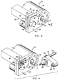
- Fig. 3 is a perspective view of an auxiliary tool member rotation device applied to the machine of Fig. 1, depicting a drive element cover in a closed position.
- Fig. 4 depicts the elements of Fig. 3, with the cover moved to the open position.
- Fig. 5 is a front elevational view of the auxiliary tool member rotation device, taken in the direction of arrow V of Fig. 3.
- Fig. 6 is a sectional view taken along the line VI-VI of Fig. 5.
- Fig. 7 depicts the elements of Fig. 6, with the cover rotated to the open position, and a tool member present in a tool-receiving socket.
- Fig. 8 is an enlarged view showing the relationship of the gears of Fig. 6, when the cover is in the open position.
- Fig. 9 is a perspective view (similar to Fig. 3) of an alternate embodiment of the invention.
- At the outset, it should be noted that attitudinal references, such as "horizontal", "vertical", "rear", "front", and the like, are provided solely for the orientation and convenience of the reader, and do not represent limitations on the various environments in which the invention may be utilized.
- Fig. 1 of the drawings exemplifies a
typical machine 10 which might employ the present invention. Themachine 10 depicted is a MAXIM CNC Horizontal Machining Center available from Cincinnati Milacron Inc., the assignee of the present invention. Themachine 10 includes a work supporting pallet 11, and aspindle carrier 12 which is vertically movable oncolumn ways 13 with respect to the work supporting pallet 11. Themachine 10 also includes atool storage chain 14. Thechain 14 holds a plurality oftools 15 which may be randomly selected and interchanged with themachine spindle 16 by means of an overhead toolchanger (not shown). Themachine spindle 16 is supported for rotation about aspindle axis 17 within acylindrical spindle housing 18 which extends from thebody 19 of thespindle carrier 12. Alltools 15 utilized in themachine 10 have a commonly configuredtapered tool shank 20, and thespindle 16 has atapered socket 21 mated to thetool shanks 20. Thespindle 16 is also provided with a pair ofdrive keys 22 which positively transfer torque from thespindle 16 totool 15 in a well-known manner. Thespindle housing 18 supports acoolant ring 23 which is stationarily held against thehousing 18 by alabyrinth seal ring 24. With reference also to Fig. 2, thecoolant ring 23 has a plurality ofholes 25 angled in a conical pattern around its inside perimeter and, when coolant is received via interdrilling 26 through thespindle housing 18, connecting with anannular distributor groove 27 at the interior face of thecoolant ring 23, coolant will be sprayed throughplural streams 28 converging at the tool cutting zone. - Referring now to Fig. 3, the
coolant ring 23 of Figs. 1 and 2 has been removed from themachine 10 and replaced by a thick, plate-like bracket 29. When viewed in the direction of arrow 5, the portion of the bracket to the right of thespindle axis 17 is shaped to the outline of thespindle housing 18, while the portion extending to the left is rectangular and carries an auxiliary servodriven toolmember rotation device 30. Theelongated bracket 29 has the same spray arrangement as thecoolant ring 23, and is likewise retained against thespindle housing 18 by thelabyrinth seal ring 24. Additionally, apin 31 has been driven through the lower part of thebracket 29 in order to angularly fix thebracket 29 with respect to thespindle axis 17. It will be appreciated by those skilled in the art that thebracket 29 depicted may be substituted-for by a variety of brackets, which may include screws, angled foot plates, etc., for attachment to thespindle housing 18. The bracket mounting technique shown provides a convenient means for optional field-retrofitting of astandard machine 10 without machining thespindle housing 18. At the left end of thebracket 29, amotor mounting plate 32 is shown affixed to the first portion orrear face 33 of thebracket 29. Themotor mounting plate 32 supports a rearwardly-extendingservomotor 34 which may be precisely controlled by a computer numerical control unit (CNC) (not shown) in a well-known manner. Theservomotor 34 has an integral resolver (not shown). Theplate 32 also serves as a housing for a pair ofpulleys drive belt 37, used for rotating the shaft of arotary limit switch 38 which is mounted directly below theservomotor 34. Theservomotor 34 is available from Siemens Energy & Automation, Inc., Industrial Motor Division, Norwood, Ohio; therotary limit switch 38 is available from the Micron Instrument Corporation, Plainview, New York. - A
cover 39, which is generally planar and circular, is mounted adjacent the second portion orfront face 40 of thebracket 29, and is rotatable about apivot axis 41 extending from thebracket 29. Thecover 39 has a radial cut-out forming atool clearance opening 42 extending from itsouter skirt 43 to a point near thepivot axis 41. - With reference to Fig. 4, the
cover 39 of Fig. 3 is shown rotated approximately 165° clockwise, to align thetool clearance opening 42 with theshaft axis 44 of theservomotor 34. Along theshaft axis 44, near thefront face 40 of thebracket 29, is a taperedregistration socket 45, and a coaxial connector means, ortorque coupling element 46, having a wedge-shapeddrive tang 47 extending across theaxis 44. Fig. 4 also shows a boring and facinghead 48, having a taperedtool shank 49 which is to be received into thespindle 16 of themachine 10. Thehead 48 has a radially-extendingarm 50 which supports aninput tool member 51, mated to register, or seat, in the taperedtool registration socket 45, and therein engage thedrive tang 47 which is spring-biased to the outward position, i.e., towards thefront face 40 of thebracket 29. Theinput tool member 51 positions atool 52 along a U-axis, transverse to thespindle axis 17. This type ofhead 48 is commercially available from the Kennametal Inc., Metalworking Systems Division, Raleigh, North Carolina, as the UCENTER boring head series. - Turning now to Fig. 5, this front elevational view shows the
bracket 29 held against thespindle housing 18 by thelabyrinth seal ring 24, and thebracket 29 being angularly fixed with respect to thehousing 18 andspindle axis 17 by means of astraight pin 31 extending through the lower part of thebracket 29 and into thehousing 18. Theservomotor mounting plate 32 extends slightly above the top surface of thebracket 29. - The
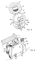
cover 39 is shown in the covered or "closed" position, i.e., with the radially-extendingtool clearance opening 42 pointing downwardly. In this position, thedrive tang 47 andregistration socket 45 of Fig. 4 are shielded from flying chips and the like. Thedrive tang 47 has anintegral driving gear 53, which, when atool member 51 is absent from therotation device 30, is spring-biased to enmesh with the same size drivengear 54 which is rotatable about the cover pivot axis 41 (see also Fig. 6). Although a 1:1 gear ratio is depicted, other ratios may be suitable for certain installations. Thus, it can be seen in Fig. 5 that when a boring and facinghead 48 is absent from themachine 10, thecover 39 may be driven clockwise through an angle Θ of approximately 165°, to an open position, in order to expose thedrive tang 47 andregistration socket 45 for receiving atool member 51. Following a tool member removal, thecover 39 may be rotated in a counterclockwise direction to close thecover 39 and again shield thedrive tang 47 andregistration socket 45. - Referring now to the details of Fig. 6, the
motor mounting plate 32, affixed to therear face 33 of thebracket 29, supports theservomotor 34. Themotor 34 is positioned on theplate 32 by itspilot diameter 55 located in theplate 32. Themotor mounting plate 32 has a machinedrelief 56 to house theswitch drive belt 37 which is shown trained around theservomotor shaft pulley 35. Thepulley 35 is driven by a straight key 57 extending along themotor shaft 58 within akeyseat 59. Aflanged adapter 60 is secured within acounterbore 61 in therear face 33 of thebracket 29 and extends through aconcentric bore 61 in thebracket 29. Thepilot diameter 62 of theadapter 60, adjacent itsflange 63, has anannular groove 64 formed between two axially spaced O-rings 65 to connect a bracketair supply line 66 to a plurality of radially extendingholes 67 within the adapter 60 (only one is depicted) to provide purging air streams to assist in keeping theregistration socket 45 and drivetang 47 clean. The stationaryconical socket 45 converges inwardly from the front face 68 of theadapter 60, terminating at aseal counterbore 69. Theseal counterbore 69 supports a shaft seal 70, shouldered within theadapter 60, adjacent to a clearance bore 71 extending through theadapter 60 to a rear clearance counterbore 72. Thedrive tang 47 extends frontwardly (i.e., to the left of Fig. 6) and has an adjacentsmooth shaft portion 73 which extends through the seal 70 to theintegral driving gear 53. Thedriving gear 53 is immediately followed by astraight hub 74. Thehub 74 extends through, and supports thereon, a preloaded helicalcompression biasing spring 75. The biasingspring 75 reacts against theservomotor pulley 35 and forces the drivinggear 53 to a frontward position resting against the bottom 76 of the clearance counterbore 72 of theadapter 60. Thedrive tang 47 is slideably carried on theservomotor shaft 58 by aprecise bore 77 in itshub 74. Akeyway 78 within thebore 77 cooperates with thestraight key 57 of themotor shaft 58 to accommodate rearward movement of thetang 47 when the biasingspring 75 is overcome, while maintaining a positive torque connection between thedrive tang 47 and themotor shaft 58. Thedriving gear 53 is shown in mesh with the drivengear 54, both of the same proportions, where the drivengear 54 is integral with apivot shaft 79 rotatable about thecover pivot axis 41. Thepivot shaft 79 has asmall head 80 after the drivengear 54. The drivengear 54 runs within a radial clearance slot 81 cut through thepilot diameter 62 of theadapter 60. Thepivot shaft 79 is journalled for rotation within aflanged bushing 82 received within agear relief 83 machined in therear face 33 of thebracket 29, and the drivengear 54 is restrained from endwise movement between thebushing 82, adjacent thegear 54, and theflange 63 of theadapter 60, adjacent thesmall head 80 of theshaft 79. Thepivot shaft 79 extends frontwardly and is received through thecentral collar 84 of thecover 39. Thecover 39 is shown with thetool clearance opening 42 extending downwardly, and has its generally planar disk 85 surrounded by a shortcylindrical skirt 43. Theskirt 43, disk 85, andcollar 84 are welded in unitary assembly, and thecollar 84 is fixed to theshaft 79 by apin 86. Rotation of theservomotor shaft 58 and itsdriving gear 53 will cause the drivengear 54 and cover 39 to be rotated to the open position shown in Fig. 4. - Refer now to Fig. 7. After the
cover 39 is rotated to the open position, and aninput tool member 51 of a boring and facinghead 48 is received within theregistration socket 45 and coupled to thedrive tang 47 as shown, the biasingspring 75 is overcome, and thedriving gear 53 is axially displaced through a distance "X"; at this time, thegears gears cover 39 and drivengear 54 from rotating, but it is preferred that the drivengear 54 be maintained in a positive, known position so that theservomotor 34 can quickly and easily find the driven gear tooth space with a driving gear tooth for re-enmeshing thegears notch 87 is provided in the face of the drivengear 54 adjacent the flanged bushing 82 (see Fig. 6 for notch cross-section), and adetent mechanism 88 is utilized. With reference to Figs. 7 and 8 for details, thedetent mechanism 88 comprises acylindrical plug 89, having acircular flange 90 with chordal flats 91a,b, each sloping away from thecollar 84 at approximately 15° to the horizontal, to provide a good range of rotation for theplug 89. Theplug 89 is received through abore 92 in thefront face 40 of thebracket 29 and is held to thebracket 29 by ascrew 93 extending through anarcuate slot 94 in theflange 90. Theinner face 95 of theplug 89 has a drilledhole 96 containing apreloaded compression spring 97; thespring 97 acts to bias aball 98 against the face of thegear 54. As shown in Figs. 7 and 8, theball 98 is received within thegear notch 87 when thecover 39 is in the open position, and remains so, until thedriving gear 53 re-enmeshes the drivengear 54 upon removal of the boring and facinghead 48 from themachine 10. - As shown exaggerated in Fig. 8, the drilled
hole 96 is eccentric to thecylindrical plug 89 by a small radial amount, "e", e.g., 1.5 mm. This radial eccentricity allows theball 98 to be thrown to the right or left of center a small amount as theplug 89 is rotated, so that thegears tang 47 with respect to thespindle axis 17 of themachine 10. - The alternate embodiment of Fig. 9 shows a fixed, box-like
inner cover 99 cooperating with theouter cover 39, to substantially fill theclearance opening 42 when theouter cover 39 is in the closed position, and prevent entry of long stringy chips which might otherwise worm their way into the protected socket area. Theinner cover 99 fits over thedetent plug 89 andflange 90, and may be fabricated of sheet metal. The box-like cover 99 has a flat, open top 100 near thecollar 84 of theouter cover 39, and has a closedarcuate bottom 101 closely conforming to the inside diameter of theouter cover skirt 43.Screws 102 passing through side flanges 103,104 secure theinner cover 99 to thebracket 29. - While a disk-
like cover 39 has been shown, it will be appreciated that many other shapes may be utilized, and, covers without openings may also be employed so long as they may be moved to cover and uncover thedrive tang 47 andregistration socket 45, or equivalent components of a similar motorized unit.
cover means for selectively covering and uncovering at least a portion of said connector means, said cover means being movably mounted on said support means; and
cover drive means for moving said cover means, said cover drive means being drivingly connected to said rotation device when said second means is disengaged from said rotation device and said cover drive means being disconnected from said rotation device when said second means is engaged with said rotation device.
Claims (9)
- A device for driving a detachable tool member (49) of a machine, comprising:(a) a supporting member (29) having means (31) for attaching said member to a machine;(b) motor means (34) for driving said tool member, said motor means having a rotary shaft and being affixed to said supporting member (29), and(c) connector means (46, 47) on the axis (44) of said shaft for detachably coupling said rotary shaft to said tool member;characterised by the provision of(d) cover means (39) movably mounted on said supporting member for selectively covering and uncovering said connector means; and(e) cover drive means (53, 54) for moving said cover means (39), said cover drive means being drivingly connected to said rotary shaft when said tool member is uncoupled from said connector means, and being disconnected from said rotary shaft when said tool member is coupled to said connector means.
- The device of Claim 1, further characterised by pivot means (79, 84) for pivotally mounting said cover means (39) on said support member (29).
- The device of Claim 1 or Claim 2, further characterised by the supporting member (29) having a first portion (33), a second portion (40), and a tool clearance surface extending between the first and second portions; said motor means being affixed to said supporting member (29), proximal said first portion, said rotary shaft extending toward said second portion along the axis (44).
- The device according to any one of the preceding claims further characterised in that the connector means (46, 47) comprises a connector element (47) movable between a first position corresponding to a tool absence condition and a second position corresponding to a tool presence condition, said cover drive means (53, 54) being drivingly connected to said rotary shaft when said connector element (47) is in said first position, and being disconnected from said rotary shaft when said connector element is in said second position.
- The device of Claim 4, further characterised by the provision of biasing means (75) for biasing said connector means to said first position, wherein said biasing means is overcome by a tool member (51) received for coupling with said connector element.
- The device according to any one of the preceding claims wherein said cover drive means includes a driving gear means (53) and the cover means includes a driven gear means (54) for engaging said driving gear means.
- The device according to any one of the preceding claims wherein said cover means (39) includes a cover having a substantially planar portion.
- The device according to Claim 7 wherein said cover includes a tool clearance opening (42) through said planar portion.
- For use in a machine tool having a spindle (16) rotatable about a spindle axis (17), the combination comprising:a) support means affixed to the machine tool;b) a rotation device supported by said support means and laterally spaced from the spindle axis, said rotation device including means for precisely-controlling its rotary movement and connector means (46, 47) for detachably connecting thereto a tool member (49), andc) a boring and facing head (48) includingcharacterised by the provision ofi) a body adapted to be inserted into the spindle of the machine tool, and retained therewith;ii) a tool (52),iii) first means (45, 51), coupled to said body and said tool, for supporting said tool for movement transversely of said body with respect to the spindle axis;iv) second means, coupled to said first means and slidingly engageable with said rotation device for moving said tool transversely of said body in a precision controlled manner, said second means being laterally-spaced from said body and the spindle axis;
cover means (39) for selectively covering and uncovering at least a portion of said connector means, said cover means being movably mounted on said support means; and
cover drive means (35, 36) for moving said cover means (39), said cover drive means being drivingly connected to said rotation device when said second means is disengaged from said rotation device and said cover drive means being disconnected from said rotation device when said second means is engaged with said rotation device.
Applications Claiming Priority (2)
| Application Number | Priority Date | Filing Date | Title |
|---|---|---|---|
| US07/903,401 US5246414A (en) | 1992-06-24 | 1992-06-24 | Cover for tool member rotation device |
| US903401 | 1992-06-24 |
Publications (3)
| Publication Number | Publication Date |
|---|---|
| EP0576272A2 EP0576272A2 (en) | 1993-12-29 |
| EP0576272A3 EP0576272A3 (en) | 1994-08-17 |
| EP0576272B1 true EP0576272B1 (en) | 1996-08-21 |
Family
ID=25417440
Family Applications (1)
| Application Number | Title | Priority Date | Filing Date |
|---|---|---|---|
| EP93304912A Expired - Lifetime EP0576272B1 (en) | 1992-06-24 | 1993-06-23 | Device for driving a detachable tool member, and combination comprising the device and a boring and facing head |
Country Status (3)
| Country | Link |
|---|---|
| US (1) | US5246414A (en) |
| EP (1) | EP0576272B1 (en) |
| DE (1) | DE69304149T2 (en) |
Families Citing this family (11)
| Publication number | Priority date | Publication date | Assignee | Title |
|---|---|---|---|---|
| US5782151A (en) * | 1995-08-07 | 1998-07-21 | Kitagawa Iron Works Co., Ltd. | Workpiece transfer apparatus |
| US7029209B2 (en) | 2000-12-18 | 2006-04-18 | Cardemon, Inc. | Slidable boring tool with fine adjustment |
| MXPA03005423A (en) | 2000-12-18 | 2005-07-01 | Cardemon Inc | Adjustment method and apparatus for a boring tool. |
| DE102004007472A1 (en) * | 2004-02-13 | 2005-09-01 | Grob-Werke Burkhart Grob E.K. | Machine tool with a headstock |
| JP5374771B2 (en) | 2009-11-10 | 2013-12-25 | 株式会社森精機製作所 | Machine tools and tool holders |
| US9221112B2 (en) | 2010-03-10 | 2015-12-29 | Milwaukee Electric Tool Corporation | Motor mount for a power tool |
| JP2015066674A (en) * | 2013-10-01 | 2015-04-13 | ファナック株式会社 | Installation part structure between spindle and tool holder in machine tool |
| CN110091125B (en) * | 2019-04-12 | 2020-06-23 | 沈阳透平机械股份有限公司 | A method for processing water lines on the flange sealing surface of compressor air cylinders for pipelines |
| US20210362281A1 (en) * | 2020-05-20 | 2021-11-25 | Atkinson International, Inc. | Unloader/Pusher Tube Debris Removal System |
| US12129848B2 (en) * | 2021-05-12 | 2024-10-29 | Johnson & Johnson Surgical Vision, Inc. | Disposable pump cartridge |
| US12473915B2 (en) | 2022-10-31 | 2025-11-18 | Johnson & Johnson Surgical Vision, Inc. | Apparatus and method for mechanically coupling a motor to a rotor of a progressive cavity pump |
Family Cites Families (13)
| Publication number | Priority date | Publication date | Assignee | Title |
|---|---|---|---|---|
| US3512817A (en) * | 1967-12-15 | 1970-05-19 | Cincinnati Milling Machine Co | Connector |
| JPS5315229B2 (en) * | 1974-02-26 | 1978-05-23 | ||
| US4354305A (en) * | 1978-12-21 | 1982-10-19 | Giddings & Lewis, Inc. | Contouring and threading attachment for multi-function machine tools |
| JPS56160738U (en) * | 1980-04-26 | 1981-11-30 | ||
| IT1134870B (en) * | 1980-12-23 | 1986-08-20 | Andrea Spa D | HEAD FOR BORING AND FACING, AS WELL AS MACHINE TOOL SUITED TO RECEIVE THIS HEAD |
| SU1076257A1 (en) * | 1983-02-15 | 1984-02-29 | Ивановское Специальное Конструкторское Бюро Расточных Станков | Faceplate for boring machine |
| DE3316867A1 (en) * | 1983-05-07 | 1984-11-08 | Mauser-Werke Oberndorf Gmbh, 7238 Oberndorf | INTERCHANGEABLE TURNING HEAD, IN PARTICULAR PANEL TURNING HEAD |
| SU1175664A1 (en) * | 1983-12-27 | 1985-08-30 | Melitopol Z Traktornykh Gidroa | Protective device for metal-working machine tool |
| US4612831A (en) * | 1985-02-19 | 1986-09-23 | Lehmkuhl Robert A | Automatic boring tool |
| DE8706644U1 (en) * | 1987-05-08 | 1987-09-03 | Deckel Maho GmbH, 87459 Pfronten | Locking piece for the working spindle of a milling and drilling machine |
| DD272764A3 (en) * | 1987-06-05 | 1989-10-25 | Werkzeugmasch Forschzent | PROTECTION DEVICE ON A TOOL MACHINE |
| US4930953A (en) * | 1989-11-06 | 1990-06-05 | Fischer Steven P | Enclosed drum collet storage system |
| DE4019510A1 (en) * | 1990-03-07 | 1991-09-12 | Hata Seisakusho Co | Tool-mounting protection equipment - is used in magazine and comprises inserted elastic plug with boss at end |
-
1992
- 1992-06-24 US US07/903,401 patent/US5246414A/en not_active Expired - Fee Related
-
1993
- 1993-06-23 EP EP93304912A patent/EP0576272B1/en not_active Expired - Lifetime
- 1993-06-23 DE DE69304149T patent/DE69304149T2/en not_active Expired - Fee Related
Also Published As
| Publication number | Publication date |
|---|---|
| DE69304149T2 (en) | 1996-12-19 |
| US5246414A (en) | 1993-09-21 |
| EP0576272A2 (en) | 1993-12-29 |
| EP0576272A3 (en) | 1994-08-17 |
| DE69304149D1 (en) | 1996-09-26 |
Similar Documents
| Publication | Publication Date | Title |
|---|---|---|
| EP0576272B1 (en) | Device for driving a detachable tool member, and combination comprising the device and a boring and facing head | |
| EP0305616B1 (en) | Machining center comprising a fluid delivery device | |
| EP0178944B1 (en) | Industrial robots | |
| EP0527238B1 (en) | Machine tool | |
| US3893355A (en) | Coolant supply system for cutting tools in a machine tool | |
| US11090732B2 (en) | Tool holder for turret lathe | |
| US5413439A (en) | Universal spindle head for machine tool | |
| JPH04261739A (en) | Tool holding device | |
| EP0072657B1 (en) | An attachment for fitting to a drive spindle of a machine | |
| WO1996019310B1 (en) | Front-loading rotary ring cutter | |
| EP0233410B1 (en) | Portable lathe | |
| US6241436B1 (en) | Adjustment and/or alignment arrangement | |
| US6312200B1 (en) | Method and apparatus for adjusting a tool cartridge, such as a cutter body | |
| EP0564296B1 (en) | Main spindle apparatus of machine tool | |
| EP1105239B1 (en) | Quick return feed for machine tool | |
| US5133629A (en) | Tool holding assembly provided with a feeler device | |
| EP0343315B1 (en) | Break away tool element and method of mounting | |
| US5286146A (en) | Operating head for automatic machine tools with chuck support angular locking devices | |
| JPS61288951A (en) | Milling machine or drilling machine | |
| CA1274378A (en) | Machine tool | |
| JPH0325855Y2 (en) | ||
| KR20020020671A (en) | Method and tool holder for turning inside contours of workpieces | |
| US20020017888A1 (en) | C-axis driving system for machine tools | |
| US4355548A (en) | Tool turret | |
| EP0841121B1 (en) | Rotating-tool fixing structure in a tool turret |
Legal Events
| Date | Code | Title | Description |
|---|---|---|---|
| PUAI | Public reference made under article 153(3) epc to a published international application that has entered the european phase |
Free format text: ORIGINAL CODE: 0009012 |
|
| AK | Designated contracting states |
Kind code of ref document: A2 Designated state(s): CH DE FR GB IT LI |
|
| PUAL | Search report despatched |
Free format text: ORIGINAL CODE: 0009013 |
|
| AK | Designated contracting states |
Kind code of ref document: A3 Designated state(s): CH DE FR GB IT LI |
|
| 17P | Request for examination filed |
Effective date: 19941004 |
|
| 17Q | First examination report despatched |
Effective date: 19941222 |
|
| GRAH | Despatch of communication of intention to grant a patent |
Free format text: ORIGINAL CODE: EPIDOS IGRA |
|
| GRAH | Despatch of communication of intention to grant a patent |
Free format text: ORIGINAL CODE: EPIDOS IGRA |
|
| GRAA | (expected) grant |
Free format text: ORIGINAL CODE: 0009210 |
|
| AK | Designated contracting states |
Kind code of ref document: B1 Designated state(s): CH DE FR GB IT LI |
|
| ITF | It: translation for a ep patent filed | ||
| REG | Reference to a national code |
Ref country code: CH Ref legal event code: NV Representative=s name: ISLER & PEDRAZZINI AG |
|
| REF | Corresponds to: |
Ref document number: 69304149 Country of ref document: DE Date of ref document: 19960926 |
|
| ET | Fr: translation filed |
Free format text: CORRECTIONS |
|
| PLBE | No opposition filed within time limit |
Free format text: ORIGINAL CODE: 0009261 |
|
| STAA | Information on the status of an ep patent application or granted ep patent |
Free format text: STATUS: NO OPPOSITION FILED WITHIN TIME LIMIT |
|
| PG25 | Lapsed in a contracting state [announced via postgrant information from national office to epo] |
Ref country code: LI Free format text: LAPSE BECAUSE OF NON-PAYMENT OF DUE FEES Effective date: 19970630 Ref country code: CH Free format text: LAPSE BECAUSE OF NON-PAYMENT OF DUE FEES Effective date: 19970630 |
|
| 26N | No opposition filed | ||
| REG | Reference to a national code |
Ref country code: CH Ref legal event code: PL |
|
| PG25 | Lapsed in a contracting state [announced via postgrant information from national office to epo] |
Ref country code: FR Free format text: LAPSE BECAUSE OF NON-PAYMENT OF DUE FEES Effective date: 19980227 |
|
| REG | Reference to a national code |
Ref country code: FR Ref legal event code: ST |
|
| REG | Reference to a national code |
Ref country code: FR Ref legal event code: ST |
|
| PGFP | Annual fee paid to national office [announced via postgrant information from national office to epo] |
Ref country code: GB Payment date: 19990630 Year of fee payment: 7 |
|
| PGFP | Annual fee paid to national office [announced via postgrant information from national office to epo] |
Ref country code: DE Payment date: 19990706 Year of fee payment: 7 |
|
| PG25 | Lapsed in a contracting state [announced via postgrant information from national office to epo] |
Ref country code: GB Free format text: LAPSE BECAUSE OF NON-PAYMENT OF DUE FEES Effective date: 20000623 |
|
| GBPC | Gb: european patent ceased through non-payment of renewal fee |
Effective date: 20000623 |
|
| PG25 | Lapsed in a contracting state [announced via postgrant information from national office to epo] |
Ref country code: DE Free format text: LAPSE BECAUSE OF NON-PAYMENT OF DUE FEES Effective date: 20010403 |
|
| PG25 | Lapsed in a contracting state [announced via postgrant information from national office to epo] |
Ref country code: IT Free format text: LAPSE BECAUSE OF NON-PAYMENT OF DUE FEES;WARNING: LAPSES OF ITALIAN PATENTS WITH EFFECTIVE DATE BEFORE 2007 MAY HAVE OCCURRED AT ANY TIME BEFORE 2007. THE CORRECT EFFECTIVE DATE MAY BE DIFFERENT FROM THE ONE RECORDED. Effective date: 20050623 |