EP0576137A1 - Method of forming bodies comprising a thermoset resin - Google Patents
Method of forming bodies comprising a thermoset resin Download PDFInfo
- Publication number
- EP0576137A1 EP0576137A1 EP93303834A EP93303834A EP0576137A1 EP 0576137 A1 EP0576137 A1 EP 0576137A1 EP 93303834 A EP93303834 A EP 93303834A EP 93303834 A EP93303834 A EP 93303834A EP 0576137 A1 EP0576137 A1 EP 0576137A1
- Authority
- EP
- European Patent Office
- Prior art keywords
- region
- faces
- crosslinked
- uncrosslinked
- transition
- Prior art date
- Legal status (The legal status is an assumption and is not a legal conclusion. Google has not performed a legal analysis and makes no representation as to the accuracy of the status listed.)
- Granted
Links
- 238000000034 method Methods 0.000 title claims abstract description 59
- 239000004634 thermosetting polymer Substances 0.000 title description 5
- 239000000463 material Substances 0.000 claims abstract description 48
- 230000007704 transition Effects 0.000 claims abstract description 36
- 229920001187 thermosetting polymer Polymers 0.000 claims abstract description 28
- 238000004132 cross linking Methods 0.000 claims abstract description 18
- 238000001125 extrusion Methods 0.000 claims description 23
- 229920001971 elastomer Polymers 0.000 claims description 22
- 239000005060 rubber Substances 0.000 claims description 21
- 238000000465 moulding Methods 0.000 claims description 20
- 229920000642 polymer Polymers 0.000 claims description 17
- 230000008569 process Effects 0.000 claims description 11
- 229920005989 resin Polymers 0.000 claims description 7
- 239000011347 resin Substances 0.000 claims description 7
- 238000010438 heat treatment Methods 0.000 claims description 6
- 238000005452 bending Methods 0.000 claims description 5
- 150000003673 urethanes Chemical class 0.000 claims description 3
- 239000005062 Polybutadiene Substances 0.000 claims description 2
- 239000004721 Polyphenylene oxide Substances 0.000 claims description 2
- 229920003211 cis-1,4-polyisoprene Polymers 0.000 claims description 2
- 229920001084 poly(chloroprene) Polymers 0.000 claims description 2
- 229920002857 polybutadiene Polymers 0.000 claims description 2
- 229920000728 polyester Polymers 0.000 claims description 2
- 229920000570 polyether Polymers 0.000 claims description 2
- 238000007789 sealing Methods 0.000 description 23
- 239000011521 glass Substances 0.000 description 12
- 230000005855 radiation Effects 0.000 description 8
- 238000001816 cooling Methods 0.000 description 6
- 229920006037 cross link polymer Polymers 0.000 description 5
- 229910052751 metal Inorganic materials 0.000 description 5
- 239000002184 metal Substances 0.000 description 5
- 230000002787 reinforcement Effects 0.000 description 5
- 238000012360 testing method Methods 0.000 description 5
- 229920003051 synthetic elastomer Polymers 0.000 description 4
- 239000005061 synthetic rubber Substances 0.000 description 4
- 229920002943 EPDM rubber Polymers 0.000 description 3
- 238000005304 joining Methods 0.000 description 3
- 238000004519 manufacturing process Methods 0.000 description 3
- XLYOFNOQVPJJNP-UHFFFAOYSA-N water Substances O XLYOFNOQVPJJNP-UHFFFAOYSA-N 0.000 description 3
- 229910000831 Steel Inorganic materials 0.000 description 2
- 238000000576 coating method Methods 0.000 description 2
- 230000006835 compression Effects 0.000 description 2
- 238000007906 compression Methods 0.000 description 2
- 230000000694 effects Effects 0.000 description 2
- 239000003822 epoxy resin Substances 0.000 description 2
- 238000010070 extrusion (rubber) Methods 0.000 description 2
- LNEPOXFFQSENCJ-UHFFFAOYSA-N haloperidol Chemical compound C1CC(O)(C=2C=CC(Cl)=CC=2)CCN1CCCC(=O)C1=CC=C(F)C=C1 LNEPOXFFQSENCJ-UHFFFAOYSA-N 0.000 description 2
- 239000003595 mist Substances 0.000 description 2
- 238000002156 mixing Methods 0.000 description 2
- 229920003052 natural elastomer Polymers 0.000 description 2
- 229920001194 natural rubber Polymers 0.000 description 2
- 229920000647 polyepoxide Polymers 0.000 description 2
- 239000010959 steel Substances 0.000 description 2
- 229920001169 thermoplastic Polymers 0.000 description 2
- 241000218657 Picea Species 0.000 description 1
- 230000009471 action Effects 0.000 description 1
- 239000000853 adhesive Substances 0.000 description 1
- 230000001070 adhesive effect Effects 0.000 description 1
- 229920000180 alkyd Polymers 0.000 description 1
- 239000004411 aluminium Substances 0.000 description 1
- 229910052782 aluminium Inorganic materials 0.000 description 1
- XAGFODPZIPBFFR-UHFFFAOYSA-N aluminium Chemical compound [Al] XAGFODPZIPBFFR-UHFFFAOYSA-N 0.000 description 1
- 229920003180 amino resin Polymers 0.000 description 1
- 230000008859 change Effects 0.000 description 1
- 238000006243 chemical reaction Methods 0.000 description 1
- 239000003795 chemical substances by application Substances 0.000 description 1
- 238000005352 clarification Methods 0.000 description 1
- 239000011248 coating agent Substances 0.000 description 1
- 238000004891 communication Methods 0.000 description 1
- 150000001875 compounds Chemical class 0.000 description 1
- 238000010276 construction Methods 0.000 description 1
- 238000007796 conventional method Methods 0.000 description 1
- 238000005520 cutting process Methods 0.000 description 1
- 230000004069 differentiation Effects 0.000 description 1
- 238000009792 diffusion process Methods 0.000 description 1
- 239000000806 elastomer Substances 0.000 description 1
- 235000012438 extruded product Nutrition 0.000 description 1
- 239000004744 fabric Substances 0.000 description 1
- 244000144992 flock Species 0.000 description 1
- 239000012530 fluid Substances 0.000 description 1
- 238000009413 insulation Methods 0.000 description 1
- 239000007788 liquid Substances 0.000 description 1
- 230000007246 mechanism Effects 0.000 description 1
- 150000002739 metals Chemical class 0.000 description 1
- ISWSIDIOOBJBQZ-UHFFFAOYSA-N phenol group Chemical group C1(=CC=CC=C1)O ISWSIDIOOBJBQZ-UHFFFAOYSA-N 0.000 description 1
- 229920001296 polysiloxane Polymers 0.000 description 1
- 238000007493 shaping process Methods 0.000 description 1
- 239000007787 solid Substances 0.000 description 1
- 239000007921 spray Substances 0.000 description 1
- 230000001629 suppression Effects 0.000 description 1
- 239000012815 thermoplastic material Substances 0.000 description 1
- 239000004416 thermosoftening plastic Substances 0.000 description 1
- 238000012546 transfer Methods 0.000 description 1
- 229920006337 unsaturated polyester resin Polymers 0.000 description 1
- JOYRKODLDBILNP-UHFFFAOYSA-N urethane group Chemical group NC(=O)OCC JOYRKODLDBILNP-UHFFFAOYSA-N 0.000 description 1
- 239000004636 vulcanized rubber Substances 0.000 description 1
Images


Classifications
-
- B—PERFORMING OPERATIONS; TRANSPORTING
- B29—WORKING OF PLASTICS; WORKING OF SUBSTANCES IN A PLASTIC STATE IN GENERAL
- B29D—PRODUCING PARTICULAR ARTICLES FROM PLASTICS OR FROM SUBSTANCES IN A PLASTIC STATE
- B29D99/00—Subject matter not provided for in other groups of this subclass
- B29D99/0053—Producing sealings
-
- B—PERFORMING OPERATIONS; TRANSPORTING
- B29—WORKING OF PLASTICS; WORKING OF SUBSTANCES IN A PLASTIC STATE IN GENERAL
- B29C—SHAPING OR JOINING OF PLASTICS; SHAPING OF MATERIAL IN A PLASTIC STATE, NOT OTHERWISE PROVIDED FOR; AFTER-TREATMENT OF THE SHAPED PRODUCTS, e.g. REPAIRING
- B29C35/00—Heating, cooling or curing, e.g. crosslinking or vulcanising; Apparatus therefor
- B29C35/02—Heating or curing, e.g. crosslinking or vulcanizing during moulding, e.g. in a mould
- B29C35/0266—Local curing
-
- B—PERFORMING OPERATIONS; TRANSPORTING
- B29—WORKING OF PLASTICS; WORKING OF SUBSTANCES IN A PLASTIC STATE IN GENERAL
- B29C—SHAPING OR JOINING OF PLASTICS; SHAPING OF MATERIAL IN A PLASTIC STATE, NOT OTHERWISE PROVIDED FOR; AFTER-TREATMENT OF THE SHAPED PRODUCTS, e.g. REPAIRING
- B29C48/00—Extrusion moulding, i.e. expressing the moulding material through a die or nozzle which imparts the desired form; Apparatus therefor
- B29C48/03—Extrusion moulding, i.e. expressing the moulding material through a die or nozzle which imparts the desired form; Apparatus therefor characterised by the shape of the extruded material at extrusion
- B29C48/09—Articles with cross-sections having partially or fully enclosed cavities, e.g. pipes or channels
- B29C48/10—Articles with cross-sections having partially or fully enclosed cavities, e.g. pipes or channels flexible, e.g. blown foils
-
- B—PERFORMING OPERATIONS; TRANSPORTING
- B29—WORKING OF PLASTICS; WORKING OF SUBSTANCES IN A PLASTIC STATE IN GENERAL
- B29C—SHAPING OR JOINING OF PLASTICS; SHAPING OF MATERIAL IN A PLASTIC STATE, NOT OTHERWISE PROVIDED FOR; AFTER-TREATMENT OF THE SHAPED PRODUCTS, e.g. REPAIRING
- B29C48/00—Extrusion moulding, i.e. expressing the moulding material through a die or nozzle which imparts the desired form; Apparatus therefor
- B29C48/03—Extrusion moulding, i.e. expressing the moulding material through a die or nozzle which imparts the desired form; Apparatus therefor characterised by the shape of the extruded material at extrusion
- B29C48/12—Articles with an irregular circumference when viewed in cross-section, e.g. window profiles
-
- B—PERFORMING OPERATIONS; TRANSPORTING
- B29—WORKING OF PLASTICS; WORKING OF SUBSTANCES IN A PLASTIC STATE IN GENERAL
- B29C—SHAPING OR JOINING OF PLASTICS; SHAPING OF MATERIAL IN A PLASTIC STATE, NOT OTHERWISE PROVIDED FOR; AFTER-TREATMENT OF THE SHAPED PRODUCTS, e.g. REPAIRING
- B29C70/00—Shaping composites, i.e. plastics material comprising reinforcements, fillers or preformed parts, e.g. inserts
- B29C70/68—Shaping composites, i.e. plastics material comprising reinforcements, fillers or preformed parts, e.g. inserts by incorporating or moulding on preformed parts, e.g. inserts or layers, e.g. foam blocks
- B29C70/84—Shaping composites, i.e. plastics material comprising reinforcements, fillers or preformed parts, e.g. inserts by incorporating or moulding on preformed parts, e.g. inserts or layers, e.g. foam blocks by moulding material on preformed parts to be joined
- B29C70/845—Shaping composites, i.e. plastics material comprising reinforcements, fillers or preformed parts, e.g. inserts by incorporating or moulding on preformed parts, e.g. inserts or layers, e.g. foam blocks by moulding material on preformed parts to be joined by moulding material on a relative small portion of the preformed parts
-
- B—PERFORMING OPERATIONS; TRANSPORTING
- B60—VEHICLES IN GENERAL
- B60J—WINDOWS, WINDSCREENS, NON-FIXED ROOFS, DOORS, OR SIMILAR DEVICES FOR VEHICLES; REMOVABLE EXTERNAL PROTECTIVE COVERINGS SPECIALLY ADAPTED FOR VEHICLES
- B60J10/00—Sealing arrangements
- B60J10/20—Sealing arrangements characterised by the shape
- B60J10/21—Sealing arrangements characterised by the shape having corner parts or bends
-
- B—PERFORMING OPERATIONS; TRANSPORTING
- B29—WORKING OF PLASTICS; WORKING OF SUBSTANCES IN A PLASTIC STATE IN GENERAL
- B29C—SHAPING OR JOINING OF PLASTICS; SHAPING OF MATERIAL IN A PLASTIC STATE, NOT OTHERWISE PROVIDED FOR; AFTER-TREATMENT OF THE SHAPED PRODUCTS, e.g. REPAIRING
- B29C2791/00—Shaping characteristics in general
- B29C2791/001—Shaping in several steps
-
- B—PERFORMING OPERATIONS; TRANSPORTING
- B29—WORKING OF PLASTICS; WORKING OF SUBSTANCES IN A PLASTIC STATE IN GENERAL
- B29C—SHAPING OR JOINING OF PLASTICS; SHAPING OF MATERIAL IN A PLASTIC STATE, NOT OTHERWISE PROVIDED FOR; AFTER-TREATMENT OF THE SHAPED PRODUCTS, e.g. REPAIRING
- B29C48/00—Extrusion moulding, i.e. expressing the moulding material through a die or nozzle which imparts the desired form; Apparatus therefor
-
- B—PERFORMING OPERATIONS; TRANSPORTING
- B29—WORKING OF PLASTICS; WORKING OF SUBSTANCES IN A PLASTIC STATE IN GENERAL
- B29K—INDEXING SCHEME ASSOCIATED WITH SUBCLASSES B29B, B29C OR B29D, RELATING TO MOULDING MATERIALS OR TO MATERIALS FOR MOULDS, REINFORCEMENTS, FILLERS OR PREFORMED PARTS, e.g. INSERTS
- B29K2105/00—Condition, form or state of moulded material or of the material to be shaped
- B29K2105/24—Condition, form or state of moulded material or of the material to be shaped crosslinked or vulcanised
- B29K2105/243—Partially cured
-
- B—PERFORMING OPERATIONS; TRANSPORTING
- B29—WORKING OF PLASTICS; WORKING OF SUBSTANCES IN A PLASTIC STATE IN GENERAL
- B29L—INDEXING SCHEME ASSOCIATED WITH SUBCLASS B29C, RELATING TO PARTICULAR ARTICLES
- B29L2031/00—Other particular articles
- B29L2031/26—Sealing devices, e.g. packaging for pistons or pipe joints
Definitions
- the present invention relates to a method of forming bodies comprising thermoset polymers and to the product of the method.
- This invention is especially suitable for forming into a desired shape, a region of a body, or bonding or joining together bodies, such as bodies of extruded elongated strips comprising thermally stable, covalently crosslinked polymers.
- the present invention especially relates to the forming into a desired shape a region of a crosslinked rubber extrudates such as vulcanized elastomeric weatherstrips and sealing or trim strips and to the joining together of such cross-linked extrudates
- Thermoset polymers are characterised by a covalently crosslinked, thermally stable network and are in contrast to thermoplastic polymers which soften and flow under heat and pressure.
- Thermosetting polymers usually crosslink under heat although some, such as urethanes and epoxy resins may require little or no heat.
- Thermosetting can occur simultaneously with polymerisation or, as in the case of vulcanised rubbers, after polymerisation.
- thermoset polymers i.e., thermally stable, covalently crosslinked polymeric materials.
- Weatherstrips, trim strips, glass run channel and the like are generally made by extruding uncured, i.e., unvulcanised elastomeric materials to form an extrudate which is then vulcanised and cut into suitable lengths. It is often desirable to further form a length of strip after vulcanising to, for example, provide a bend therein. Disadvantages arise, however, when bending already vulcanised materials. It is further often desirable to join such lengths or strips to provide an end to end joint, a T-joint or a corner.
- GB-A-2140465 discloses a reinforced sealing strip having a first glass run channel and an inversely disposed flange finisher portion which secures the structure to a window frame of a car door.
- Sealing strips of this type commonly include a flexible lip extending from the free end of the outer wall of the flange finisher portion. This lip projects over the bodywork of the vehicle door and disguises the region adjacent the flange finisher.
- the sealing strip is bent to form the desired shape to match the opening in the door, it has been found that the lip distorts badly at the bend as a result of being stretched out of shape. This provides an uneven and unattractive finish at the corners or bends of the shaped sealing strip.
- This method involves extruding unvulcanised rubber into a desired profile and vulcanizing the rubber by heating it to effect crosslinking. After the extrudate is vulcanized it is cut to the desired length to prepare it for a moulding step to join it to another length of moulding. For example, for a corner joint, the ends of a pair of extrudates are loaded into a corner mould and unvulcanised rubber is introduced into the mould cavity to form a corner section. The unvulcanised corner material is then heated to vulcanize it and bond it to the already vulcanized extrudate ends.
- this method has the disadvantage of producing a product with unsightly joint lines at the cut ends of the elongated extrudate.
- the joint obtained by the method is not as strong as the extrudate itself.
- the joint lines are due to several causes. First, when the ends of the cured extrusions are loaded into the corner mould, the mould must clamp the ends of the extrusions to withstand the cavity pressure of introduced corner material exhibited on the extrusion, therefore preventing the extrusion from being pushed out of he mould. This clamping action on the extrusion causes the extrusion to displace linearly within the extrusion clamping region.
- a third cause of unsightly joint lines is due to difference in colour between the extrudate moulded portions. Colour mismatch is unsightly and even when the same material is used for both the extrudate and moulded portions of the article, variation of the material state of crosslinking can cause an objectionable colour shift.
- a transition zone between vulcanized and unvulcanized rubber.
- colour and/or gloss mismatches are blended over a zone or area, which blending results in a less noticeable joint.
- a method of this invention avoids bonding unvulcanized rubber to a cut surface of vulcanized rubber. This method joins pieces of previously crosslinked resin at interfaces of uncrosslinked resin thus joining the pieces together with a strong bond by allowing uncrosslinked polymer chains to bridge the bonded area before being crosslinked.
- the method also facilitates bending or other forming of an extrudate comprising vulcanized resin.
- thermoset polymeric element comprising the steps of:
- the present invention also relates to the formed thermoset polymeric element made by the method of this invention.
- the polymeric element is an elongate thermoset polymeric element.
- the elongate polymeric element which is subjected to the method of the present invention is preferably formed by an extrusion process; such a process, allied to a subsequent curing step, is commonly used for the manufacture of thermoset polymeric components for the automobile industry.
- an extrusion process such a process, allied to a subsequent curing step, is commonly used for the manufacture of thermoset polymeric components for the automobile industry.
- an elongated thermoset extrudate is joined to itself or another elongated thermoset extrudate by the following steps to provide a joint or bond which is strong and without a noticeable joint line.
- a body of uncrosslinked thermosetting resin is selectively cured to provide a zone of substantially crosslinked thermally stable resin material, a one having a face of substantially uncrosslinked material, and a transition zone therebetween.
- the face, transition zone and adjacent part is placed in a mould cavity and effectively contacted with another face, transition zone and adjacent part.
- Uncrosslinked thermosetting material can be introduced into the mould to effectively contact the faces.
- the material in the mould is crosslinked, for example, by heating.
- the selective curing is within the body of the extrusion, i.e. instead of the uncured region being located at the end or face of the part, it is located with the elongated region.
- the article can be reformed into a desired curvature, placed into a fixture or mould and uncured and transition regions cured into the desired curvature.
- the elongate element in the second preferred embodiment in which the selective curing is within the body of the extrusion, in the forming step (c), the elongate element may be formed by bending into a desired curvature at the uncrosslinked location and then the uncrosslinked region and the transition region may be formed by moulding and subsequently crosslinked.
- the selective crosslinking is such that an intermediate location of the extrudate remains substantially uncrosslinked. This permits the partially finished extrudate to be reformed into a desired curvature, placed into a fixture or mould and the uncrosslinked and transition regions cured into the desired shape, for example, by heating. It is possible to introduce additional uncrosslinked thermosetting material into the mould prior to curing to contact the uncrosslinked region of the element and provide additional bulk, if necessary.
- thermosetting polymers are those which change irreversibly upon heating and are then thermally stable, i.e., are not thermoplastic.
- Thermosetting polymers may be set or crosslinked when heated, with or without additional "curing" agents or may be crosslinked to a thermoset condition by radiation or chemical reaction.
- thermosetting polymers are the phenolic, alkyds, amino resins, unsaturated polyester resins, epoxy resins, silicones, urethane forms, and elastomers such as natural or synthetic rubber.
- Synthetic rubber includes cis-1,4-polyisoprene, polybutadiene, poly(butadiene-co-styrene) (SBR), poly(butadiene-co-acrylonitrile), poly(isobutylene-co-isoprene), poly(ethylene-co-propylene-co-diene) (EPDM), polychloroprene, polydimethyisiloxane, polyalkylensulfide, polyester or polyether urethanes.
- thermoset polymer is a natural or synthetic rubber, such as the synthetic rubber EPDM.
- the method of the present invention ensures that there is no noticeable joint line at the reformed region of the finished polymeric element.
- substantially uncrosslinked and substantially crosslinked are used herein to refer to relatively lowly crosslinked polymer and relatively highly crosslinked polymer respectively.
- the particular percentages of crosslinking will depend upon the particular polymer involved.
- Relatively lowly crosslinked polymer is a processable material, i.e., extrudable polymer.
- Relatively highly crosslinked polymer is crosslinked to a state that is stable, i.e., the polymer is suitable for the desired end use.
- the elongate extrudate is a sealing strip comprising a mounting portion for mounting the strip on a vehicle and a sealing lip which is formed with the mounting portion and extends away therefrom.
- the mounting portion is substantially crosslinked whilst at least a part of the lip remains uncrosslinked; a partially crosslinked transition region is also formed between the crosslinked and uncrosslinked regions.
- the sealing strip is formed into a desired curvature by being bent about a point which coincides with the uncrosslinked part of the lip. Following this forming operation, the uncrosslinked part of the lip is moulded to a desired shape and then subsequently crosslinked.
- the lip can be made to be substantially undistorted at the region of the said bend.
- the mounting portion is preferably channel-shaped having a base and two side walls and is adapted to be received by a flange.
- the mounting portion is preferably rigid and this rigidity may be provided by a reinforcement member which preferably extends through the base and side walls.
- the mounting portion could have a flexible core such as wire carrier or lanced steel.
- the thermoset polymeric material is provided as a coating on the reinforcement member.
- the mounting portion may have means known per se for securing it to a flange, such as ribs which project from the side walls of the channel towards the base.
- the reinforcement member which may be embedded in the mounting portion, may be solid or apertured and may be made of a metal such as steel or aluminium. Other reinforcements, including ones woven from metal wire are also operable.
- the mounting portion may consist of a rigid thermoset polymer, such as one which is no softer than 90° Shore A, and preferably no softer than 50° + Shore D and this dispenses with the need for a conventional metal reinforcement member to provide its rigidity.
- the lip may be made of a relatively soft thermoset polymer.
- the strip may be used to seal around the window opening of a vehicle door and may include an integral glass run channel, which may be inverted with respect to the mounting portion.
- One or more sealing lips may be provided which extend from one or both of the side walls in order to seal a pane of glazing material in the channel.
- the surface of the base on the interior of the channel, and the seals extending from the side walls of the glass run channel preferably have a flock material secured thereto in order to reduce friction with the glass panel.
- the uncrosslinked region may be formed to a desired shape by a moulding operation in which the uncrosslinked polymeric material is permitted to soften thereby eliminating distortions which may be created during an earlier bending operation.
- the softened material will flow to fill the mould.
- the mould may take the form of a porous metal block provided with a vacuum system which may pull the region into the desired shape against the mould.
- the mould may be heated, if necessary, to assist softening of the uncrosslinked region.
- Different types of mould may be used which allow extensive shaping of the uncrosslinked region to be achieved.
- the region may be compression moulded to extend it and thereby provide a more aesthetic finish to the finished element.
- the mould could be provided with means for cutting the region to provide an even finish.
- Subsequent curing may be carried out by means of heat (whilst the originally uncrosslinked region is still in the mould or after removing the region from the mould) or by infrared radiation which can be targeted at the relevant region to be crosslinked.
- part of the length of the element may be shielded whilst curing the remainder of the element, for example, by infrared radiation.
- Selective curing may also be achieved by selectively cooling the part of the element to remain uncrosslinked by, for example, a water mist spray cooling system directed onto that part.
- the element may be formed of different polymers, at least one of which is susceptible to microwave radiation and at least one other of which is not. On curing the element in microwave ovens, the part of the element not susceptible to microwave radiation remains uncrosslinked. This part can then be reformed and subsequently crosslinked.
- the method of the present invention is particularly advantageous to provide glass run channel for automotive vehicles where such glass run has a corner therein.
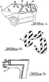
- preferred embodiments of the present invention are illustrated in Figure 1 as glass run channel 10 and windshield moulding 11 installed on an automotive vehicle 12.
- Glass run channel 10 has a corner portion 14 and windshield moulding 11 has corner portion 15 made in accordance with a preferred method of the present invention.
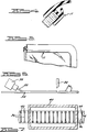
- FIG. 6 A preferred method of the present invention is well illustrated in Figures 6-11.
- a first step is schematically illustrated.
- an extruder 30 extrudes uncrosslinked, e.g., EPDM rubber extrudate 32 onto a moving belt 34.
- Extrudate 32 is cut into lengths 36 by blade 38.
- Lengths 36 are bodies of substantially uncrosslinked polymer suitable for later crosslinking to form a thermally stable polymer. As illustrated in Figure 7, lengths 36 are selectively crosslinked, i.e. cured in oven 40. By selective crosslinking or curing is meant that the length is crosslinked or cured in a manner so as to provide a substantially crosslinked zone, a substantially uncrosslinked zone and a transition zone therebetween. Thus, heat insulating shields 42 are placed over the ends of lengths 36 thereby providing at the output of oven 40, lengths 36 with substantially uncrosslinked end faces 44, crosslinked length or body portions 46, and transition zones 48 therebetween.
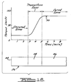
- Figure 12 shows a graph which illustrates a common material property of rubber, i.e. a rheometer curve 50.
- a rheometer curve is obtained by a test performed on a test machine such as the oscillating disk rheometer (ASTMD084) and is generally understood by those involved in the rubber industry as a test to measure the relative curing rate of a rubber material.
- the material is heated to the vulcanizing temperature (typically between 200 degrees F and 600 degrees F) under positive pressure in a sealed test chamber which contains an oscillating disk.
- the oscillating disk is attached to a strain gauge which measures the torque required to rotate the disk while the material is maintained at the curing temperature.
- Figure 12 also illustrates an extrudate length made in accordance with this step.
- the state of cure zones have been superimposed from the rheometer graph to illustrate the effect of this selective curing,
- extrudate 36 has uncrosslinked zone 44, transition zone 48 and crosslinked body 46.
- FIG. 7 it will become evident to those skilled in the art of rubber extrusion and curing that numerous methods exist which could be utilized to produce a selectively cured rubber extrusion.
- a cold air jet can be employed to spot cool the uncured zone while the extrudate is curing in a hot air oven.
- various other methods of selective curing employing heat transfer and energy management can be used such as: microwave suppression, radiation cure, liquid curing media, fluidized bed, evaporative cooling, shielding, insulation, etc.
- An example is shown in Figure 13, where an apparatus is shown for selectively cooling a lip 70 of a sealing strip to prevent curing thereof whilst the remainder of the sealing strip is crosslinked.
- the apparatus comprises water dispersing means 72 and 74 which disperse a mist 76 onto lip 70 thereby cooling it, and preventing curing thereof.
- Figure 14 shows a sealing strip which may be selectively crosslinked in accordance with the present invention.
- the sealing strip 76 comprises two different thermosetting polymeric materials 78 and 80.
- Polymeric material 78 is curable by microwave radiation and forms the main body of the sealing strip 76.
- Polymeric material 80 forms the lip 70 and is not curable by microwave radiation.
- the polymeric material 78 is crosslinked in microwave ovens and thereby leaves the lip 70 formed of polymeric material 80 uncrosslinked in accordance with the invention.
- the length 36 is selectively cured to provide uncrosslinked zone 44, transition zone 48 and crosslinked body 46, it is joined to another length 36 in a moulding process to form a corner as illustrated in Figures 8-11.
- Mould 52 comprises top half 54 and bottom half 56 having channels 58 and 60, respectively, which cooperate to form mould cavity 62.
- Top half 54 has mould spruce 64 which is in fluid communication with channel 58 and hence mould cavity 62. It will be appreciated that, while mould 52 is suitable for moulding corners, other moulds for other forms or shapes can be used herein as desired.
- Two end portions of lengths 36 are introduced into channel 60 and mould halves 54 and 56 of mould 50 are closed to capture the end portions in mould cavity 62 as illustrated in Figure 9.
- the cut end of the cured strip bonds to the uncured corner rubber via diffusion. Very little crosslinking can take place as the cut end is prevulcanized leaving few crosslinking sights available.
- the polymer chains are allowed to cross the boundaries of the cured extrudate through to the uncured region. The varying degree of crosslinking prior to moulding allows the uncured rubber and transition region of one strip to crosslink with the uncured and transition region of a second strip.
- the selective curing may be within the body of the extrusion, i.e. instead of the uncured region being located at the end or face of the part. In this way the article may be formed into its desired curvature without distortions at the bend. Once the article has been selectively cured, it is moulded to the desired shape and the previously uncrosslinked part is crosslinked.
- Figure 15 shows an apparatus for moulding the uncrosslinked lip 70 to a desired shape.
- the apparatus comprises a first mould 82 and a second mould 84.
- the moulds 82 and 84 shape lip 70 to the required shape and, in the embodiment shown comprise textured surfaces 86 and 88 which impart a pattern onto lip 70 on heating and moulding.
- Figure 16 shows an alternative method of moulding in which the heated mould extends lip 70 by means of compression caused by forcing a first mould 90 and second mould 92 towards each other with the lip 70 disposed therebetween, thereby extending the lip 70 without the need to add further rubber material.
- This type of moulding apparatus may be particularly useful in forming a sealing strip such as that shown in Figure 17 in which a flag 92 is formed from an extended lip 70 at the corner portion 94 of a B-pillar.
- the lip 70 Once the lip 70 has been reformed to its desired shape, it is subsequently crosslinked.
- Figure 18 shows an alternative sealing strip 96 known in the art for the sealing of a trunk in a sports car.
- the strip 96 comprises a lip 98, a mounting portion 100, and a sponge bulb 102 for providing a seal.
- a notch is normally made along line 104 and then the lip 98 is subsequently remoulded to the desired shape. If the process of the present invention is employed in which the lip 98 is left uncured, then moulded, and subsequently cured, the expense associated with the notching and moulding process is avoided.
Landscapes
- Engineering & Computer Science (AREA)
- Mechanical Engineering (AREA)
- Physics & Mathematics (AREA)
- Health & Medical Sciences (AREA)
- Oral & Maxillofacial Surgery (AREA)
- Thermal Sciences (AREA)
- Chemical & Material Sciences (AREA)
- Composite Materials (AREA)
- Extrusion Moulding Of Plastics Or The Like (AREA)
Abstract
- (a) providing an element (36) formed of a crosslinkable polymeric material;
- (b) selectively crosslinking said polymeric material constituting the element (36) whereby a first region (44) of the element (36) remains substantially uncrosslinked, this first region (44) being separated from a substantially crosslinked region (46) of the element (36) by a partially crosslinked transition region (48);
- (c) forming said first region (44) and transition region (48); and
- (d) substantially crosslinking said first region (44) and transition region (48) to provide a formed thermoset polymeric element.
Description
- The present invention relates to a method of forming bodies comprising thermoset polymers and to the product of the method. This invention is especially suitable for forming into a desired shape, a region of a body, or bonding or joining together bodies, such as bodies of extruded elongated strips comprising thermally stable, covalently crosslinked polymers. The present invention especially relates to the forming into a desired shape a region of a crosslinked rubber extrudates such as vulcanized elastomeric weatherstrips and sealing or trim strips and to the joining together of such cross-linked extrudates
- Thermoset polymers are characterised by a covalently crosslinked, thermally stable network and are in contrast to thermoplastic polymers which soften and flow under heat and pressure. Thermosetting polymers usually crosslink under heat although some, such as urethanes and epoxy resins may require little or no heat. Thermosetting can occur simultaneously with polymerisation or, as in the case of vulcanised rubbers, after polymerisation. It will be appreciated by those skilled in the art that the present invention is broadly applicable to the class of thermoset polymers, i.e., thermally stable, covalently crosslinked polymeric materials. However, to facilitate understanding of the invention, it is described below in the context of preferred embodiments relating to extruded vulcanised rubber strips used in the automobile industry, such as weatherstrips, trim strips and glass run channel.
- Weatherstrips, trim strips, glass run channel and the like are generally made by extruding uncured, i.e., unvulcanised elastomeric materials to form an extrudate which is then vulcanised and cut into suitable lengths. It is often desirable to further form a length of strip after vulcanising to, for example, provide a bend therein. Disadvantages arise, however, when bending already vulcanised materials. It is further often desirable to join such lengths or strips to provide an end to end joint, a T-joint or a corner.
- GB-A-2140465 discloses a reinforced sealing strip having a first glass run channel and an inversely disposed flange finisher portion which secures the structure to a window frame of a car door. Sealing strips of this type commonly include a flexible lip extending from the free end of the outer wall of the flange finisher portion. This lip projects over the bodywork of the vehicle door and disguises the region adjacent the flange finisher. However, when the sealing strip is bent to form the desired shape to match the opening in the door, it has been found that the lip distorts badly at the bend as a result of being stretched out of shape. This provides an uneven and unattractive finish at the corners or bends of the shaped sealing strip.
- A similar problem has also been found in trunk seals for sports cars, or the like. In such instances a lip is provided in order to disguise spot welds on the bodywork and to provide a gutter for rain water or the like. It has been found that when the seal is bent around the trunk aperture, the lip distorts and moves away from the bodywork at the corner regions. In the past this problem has been overcome by notching the lip away at the corners and remoulding it to the correct shape.
- One technique for solving this problem is to employ a combined extrusion and moulding process. Generally speaking, this method involves extruding unvulcanised rubber into a desired profile and vulcanizing the rubber by heating it to effect crosslinking. After the extrudate is vulcanized it is cut to the desired length to prepare it for a moulding step to join it to another length of moulding. For example, for a corner joint, the ends of a pair of extrudates are loaded into a corner mould and unvulcanised rubber is introduced into the mould cavity to form a corner section. The unvulcanised corner material is then heated to vulcanize it and bond it to the already vulcanized extrudate ends. However, this method has the disadvantage of producing a product with unsightly joint lines at the cut ends of the elongated extrudate. Also, the joint obtained by the method is not as strong as the extrudate itself. The joint lines are due to several causes. First, when the ends of the cured extrusions are loaded into the corner mould, the mould must clamp the ends of the extrusions to withstand the cavity pressure of introduced corner material exhibited on the extrusion, therefore preventing the extrusion from being pushed out of he mould. This clamping action on the extrusion causes the extrusion to displace linearly within the extrusion clamping region. Upon mould opening at the end of the corner moulding process, the displaced extrusion relaxes back to its original form due to the elastic memory of the cured rubber. This relaxation takes place unimpeded except at the joint interface between the extrusion and moulded corner where the extrusion size relaxation causes stress and a dimensional step to the moulded material. This dimensional mismatch causes appearance as well as functional, i.e. sealing, problems.
- Another cause of unsightly joint lines is due to a difference in gloss. A gloss mismatch exists between the extrudate and the moulded corner. This is due to the dissimilar processes of extrusion and moulding. Because the surfaces are joined together at a distinct line, the gloss mismatch is accentuated and is therefore unattractive from an appearance standpoint.
- A third cause of unsightly joint lines is due to difference in colour between the extrudate moulded portions. Colour mismatch is unsightly and even when the same material is used for both the extrudate and moulded portions of the article, variation of the material state of crosslinking can cause an objectionable colour shift.
- In the present invention there is a transition zone between vulcanized and unvulcanized rubber. Thus colour and/or gloss mismatches are blended over a zone or area, which blending results in a less noticeable joint. Further, a method of this invention avoids bonding unvulcanized rubber to a cut surface of vulcanized rubber. This method joins pieces of previously crosslinked resin at interfaces of uncrosslinked resin thus joining the pieces together with a strong bond by allowing uncrosslinked polymer chains to bridge the bonded area before being crosslinked. The method also facilitates bending or other forming of an extrudate comprising vulcanized resin.
- According to the present invention there is provided a method of forming a thermoset polymeric element, said method comprising the steps of:
- (a) providing an element formed of a crosslinkable polymeric material which can be crosslinked to form a thermally stable polymer;
- (b) selectively crosslinking said polymeric material constituting the element whereby a first region of the element remains substantially uncrosslinked, this first region being separated from a substantially crosslinked region of the element, by a partially crosslinked transition region;
- (c) forming said first region and transition region; and
- (d) substantially crosslinking said first region and transition region to provide a formed thermoset polymeric element.
- The present invention also relates to the formed thermoset polymeric element made by the method of this invention.
- Preferably the polymeric element is an elongate thermoset polymeric element.
- The elongate polymeric element which is subjected to the method of the present invention is preferably formed by an extrusion process; such a process, allied to a subsequent curing step, is commonly used for the manufacture of thermoset polymeric components for the automobile industry. Hereafter, for the sake of clarity, we shall refer to the elongate element as an extrudate, although it should be appreciated that the uncrosslinked polymeric element may be prepared by manufacturing processes other than extrusion.
- In accordance with a first preferred embodiment of the method of the present invention, an elongated thermoset extrudate is joined to itself or another elongated thermoset extrudate by the following steps to provide a joint or bond which is strong and without a noticeable joint line. First a body of uncrosslinked thermosetting resin is selectively cured to provide a zone of substantially crosslinked thermally stable resin material, a one having a face of substantially uncrosslinked material, and a transition zone therebetween. The face, transition zone and adjacent part is placed in a mould cavity and effectively contacted with another face, transition zone and adjacent part. Uncrosslinked thermosetting material can be introduced into the mould to effectively contact the faces. Finally, the material in the mould is crosslinked, for example, by heating.
- In a accordance with a second preferred embodiment of the present invention the selective curing is within the body of the extrusion, i.e. instead of the uncured region being located at the end or face of the part, it is located with the elongated region. In this way the article can be reformed into a desired curvature, placed into a fixture or mould and uncured and transition regions cured into the desired curvature.
- In the second preferred embodiment in which the selective curing is within the body of the extrusion, in the forming step (c), the elongate element may be formed by bending into a desired curvature at the uncrosslinked location and then the uncrosslinked region and the transition region may be formed by moulding and subsequently crosslinked.
- In the method of the present invention the selective crosslinking is such that an intermediate location of the extrudate remains substantially uncrosslinked. This permits the partially finished extrudate to be reformed into a desired curvature, placed into a fixture or mould and the uncrosslinked and transition regions cured into the desired shape, for example, by heating. It is possible to introduce additional uncrosslinked thermosetting material into the mould prior to curing to contact the uncrosslinked region of the element and provide additional bulk, if necessary.
- The present method is applicable to a broad range of thermosetting polymers. Such polymers are those which change irreversibly upon heating and are then thermally stable, i.e., are not thermoplastic. Thermosetting polymers may be set or crosslinked when heated, with or without additional "curing" agents or may be crosslinked to a thermoset condition by radiation or chemical reaction. Examples of thermosetting polymers are the phenolic, alkyds, amino resins, unsaturated polyester resins, epoxy resins, silicones, urethane forms, and elastomers such as natural or synthetic rubber. Synthetic rubber includes cis-1,4-polyisoprene, polybutadiene, poly(butadiene-co-styrene) (SBR), poly(butadiene-co-acrylonitrile), poly(isobutylene-co-isoprene), poly(ethylene-co-propylene-co-diene) (EPDM), polychloroprene, polydimethyisiloxane, polyalkylensulfide, polyester or polyether urethanes.
- In preferred embodiments of the present invention, the thermoset polymer is a natural or synthetic rubber, such as the synthetic rubber EPDM.
- The method of the present invention ensures that there is no noticeable joint line at the reformed region of the finished polymeric element.
- It will be appreciated by those skilled in the art that the terms substantially uncrosslinked and substantially crosslinked are used herein to refer to relatively lowly crosslinked polymer and relatively highly crosslinked polymer respectively. The particular percentages of crosslinking will depend upon the particular polymer involved. Relatively lowly crosslinked polymer is a processable material, i.e., extrudable polymer. Relatively highly crosslinked polymer is crosslinked to a state that is stable, i.e., the polymer is suitable for the desired end use.
- In a preferred aspect of the present invention, the elongate extrudate is a sealing strip comprising a mounting portion for mounting the strip on a vehicle and a sealing lip which is formed with the mounting portion and extends away therefrom. In the method of manufacture of the strip, the mounting portion is substantially crosslinked whilst at least a part of the lip remains uncrosslinked; a partially crosslinked transition region is also formed between the crosslinked and uncrosslinked regions. The sealing strip is formed into a desired curvature by being bent about a point which coincides with the uncrosslinked part of the lip. Following this forming operation, the uncrosslinked part of the lip is moulded to a desired shape and then subsequently crosslinked. As a result of the invention, the lip can be made to be substantially undistorted at the region of the said bend.
- In this preferred aspect of the invention, the mounting portion is preferably channel-shaped having a base and two side walls and is adapted to be received by a flange. The mounting portion is preferably rigid and this rigidity may be provided by a reinforcement member which preferably extends through the base and side walls. Alternatively, the mounting portion could have a flexible core such as wire carrier or lanced steel. The thermoset polymeric material is provided as a coating on the reinforcement member. The mounting portion may have means known per se for securing it to a flange, such as ribs which project from the side walls of the channel towards the base.
- The reinforcement member, which may be embedded in the mounting portion, may be solid or apertured and may be made of a metal such as steel or aluminium. Other reinforcements, including ones woven from metal wire are also operable. Alternatively, the mounting portion may consist of a rigid thermoset polymer, such as one which is no softer than 90° Shore A, and preferably no softer than 50° + Shore D and this dispenses with the need for a conventional metal reinforcement member to provide its rigidity. In such an embodiment the lip may be made of a relatively soft thermoset polymer.
- In a preferred embodiment, the strip may be used to seal around the window opening of a vehicle door and may include an integral glass run channel, which may be inverted with respect to the mounting portion. One or more sealing lips may be provided which extend from one or both of the side walls in order to seal a pane of glazing material in the channel. The surface of the base on the interior of the channel, and the seals extending from the side walls of the glass run channel preferably have a flock material secured thereto in order to reduce friction with the glass panel.
- In the second preferred embodiment of the invention, the uncrosslinked region may be formed to a desired shape by a moulding operation in which the uncrosslinked polymeric material is permitted to soften thereby eliminating distortions which may be created during an earlier bending operation. The softened material will flow to fill the mould. In one embodiment, the mould may take the form of a porous metal block provided with a vacuum system which may pull the region into the desired shape against the mould. The mould may be heated, if necessary, to assist softening of the uncrosslinked region. Different types of mould may be used which allow extensive shaping of the uncrosslinked region to be achieved. For example, the region may be compression moulded to extend it and thereby provide a more aesthetic finish to the finished element. Alternatively, the mould could be provided with means for cutting the region to provide an even finish.
- Subsequent curing may be carried out by means of heat (whilst the originally uncrosslinked region is still in the mould or after removing the region from the mould) or by infrared radiation which can be targeted at the relevant region to be crosslinked.
- With regard to the selective curing of the element, this may be achieved by various methods. For instance, part of the length of the element may be shielded whilst curing the remainder of the element, for example, by infrared radiation. Selective curing may also be achieved by selectively cooling the part of the element to remain uncrosslinked by, for example, a water mist spray cooling system directed onto that part. Alternatively, the element may be formed of different polymers, at least one of which is susceptible to microwave radiation and at least one other of which is not. On curing the element in microwave ovens, the part of the element not susceptible to microwave radiation remains uncrosslinked. This part can then be reformed and subsequently crosslinked.
- The invention will be best understood from the accompanying drawings, taken in conjunction with the accompanying description, and in which:
- Figure 1 is a perspective view, broken away, of an automotive vehicle having preferred embodiments of the present invention installed thereon;
- Figure 2 is a sectional view, taken along line 2-2 of Figure 1 and showing a glass run channel;
- Figure 3 is an enlarged perspective view, partially in section and broken away, of the circle in Figure 1 indicated by the
numeral 3 and showing a corner of the glass run channel; - Figure 4 is a sectional view, broken away, taken along line 4-4 in Figure 1 and showing a windshield moulding;
- Figure 5 is an enlarged perspective view, partially in section and broken away, of the circle in Figure 1 indicated by the
numeral 5 and showing a corner of the windshield moulding; - Figure 6-11 are perspective views, broken away, illustrating steps of a preferred method of the present invention;
- Figure 12 is a graph illustrating the selective crosslinking of the present invention;
- Figure 13 shows a method of selectively cooling a sealing strip;
- Figure 14 shows, in cross-section, a sealing strip formed of two different materials;
- Figure 15 shows a cross-section, a sealing strip being moulded;
- Figure 16 shows a cross-section of a sealing strip being moulded in an alternative manner;
- Figure 17 shows one embodiment of a moulded corner portion of the sealing strip; and
- Figure 18 shows a cross-section of a trunk seal in accordance with the prior art.
- The method of the present invention is particularly advantageous to provide glass run channel for automotive vehicles where such glass run has a corner therein. Thus, preferred embodiments of the present invention are illustrated in Figure 1 as
glass run channel 10 and windshield moulding 11 installed on anautomotive vehicle 12.Glass run channel 10 has a corner portion 14 and windshield moulding 11 hascorner portion 15 made in accordance with a preferred method of the present invention. - A preferred method of the present invention is well illustrated in Figures 6-11. Referring to Figure 6, a first step is schematically illustrated. Thus, an
extruder 30 extrudes uncrosslinked, e.g., EPDM rubber extrudate 32 onto a movingbelt 34. Extrudate 32 is cut intolengths 36 byblade 38. -
Lengths 36 are bodies of substantially uncrosslinked polymer suitable for later crosslinking to form a thermally stable polymer. As illustrated in Figure 7,lengths 36 are selectively crosslinked, i.e. cured inoven 40. By selective crosslinking or curing is meant that the length is crosslinked or cured in a manner so as to provide a substantially crosslinked zone, a substantially uncrosslinked zone and a transition zone therebetween. Thus, heat insulating shields 42 are placed over the ends oflengths 36 thereby providing at the output ofoven 40,lengths 36 with substantially uncrosslinked end faces 44, crosslinked length orbody portions 46, andtransition zones 48 therebetween. - Further understanding of the term selective curing as used herein can be had by referring to Figures 12. Figure 12 shows a graph which illustrates a common material property of rubber, i.e. a
rheometer curve 50. A rheometer curve is obtained by a test performed on a test machine such as the oscillating disk rheometer (ASTMD084) and is generally understood by those involved in the rubber industry as a test to measure the relative curing rate of a rubber material. In this test the material is heated to the vulcanizing temperature (typically between 200 degrees F and 600 degrees F) under positive pressure in a sealed test chamber which contains an oscillating disk. The oscillating disk is attached to a strain gauge which measures the torque required to rotate the disk while the material is maintained at the curing temperature. - Superimposed over the rheometer there are three zones identified for clarification as: "uncured zone", "transition zone" and "cured zone". These zones are generalized to show three distinct states of matter in the process of vulcanizing rubber or in industry terms to show the state of cure. It is contemplated that the uncured zone is substantially uncrosslinked with the transition zone representing a gradual transition between the uncured and cured zones. In the present invention it will be evident that all three zones or states of matter of an extruded article are employed to produce an extruded product with moulded corners without visible joint lines between the extruded and moulded portions. In the present invention, extrusions are produced in a preparatory step and cut into a unit length. However, at the region of the cut is superimposed a region of uncured zone of rubber. Additionally, adjacent to the uncured zone is material in the transition zone sandwiched between the uncured and cured zones.
- Figure 12 also illustrates an extrudate length made in accordance with this step. The state of cure zones have been superimposed from the rheometer graph to illustrate the effect of this selective curing, Thus,
extrudate 36 has uncrosslinkedzone 44,transition zone 48 andcrosslinked body 46. - Referring back to Figure 7, it will become evident to those skilled in the art of rubber extrusion and curing that numerous methods exist which could be utilized to produce a selectively cured rubber extrusion. For example, a cold air jet can be employed to spot cool the uncured zone while the extrudate is curing in a hot air oven. Alternatively, various other methods of selective curing employing heat transfer and energy management can be used such as: microwave suppression, radiation cure, liquid curing media, fluidized bed, evaporative cooling, shielding, insulation, etc. An example is shown in Figure 13, where an apparatus is shown for selectively cooling a
lip 70 of a sealing strip to prevent curing thereof whilst the remainder of the sealing strip is crosslinked. The apparatus comprises water dispersing means 72 and 74 which disperse amist 76 ontolip 70 thereby cooling it, and preventing curing thereof. - Figure 14 shows a sealing strip which may be selectively crosslinked in accordance with the present invention. In this embodiment, the sealing
strip 76 comprises two different thermosettingpolymeric materials Polymeric material 78 is curable by microwave radiation and forms the main body of the sealingstrip 76.Polymeric material 80 forms thelip 70 and is not curable by microwave radiation. Thepolymeric material 78 is crosslinked in microwave ovens and thereby leaves thelip 70 formed ofpolymeric material 80 uncrosslinked in accordance with the invention. - It must be pointed out that while the three state of cure zones are illustrated in Figure 12 with distinct cross-sectional differentiation, forms of the present invention exist in which a cross-sectional slice contains material in two or three forms. In this way only selective regions such as the show surface contain material in the uncured zone. It can also be appreciated that while the illustration depicts an extrusion produced from a single material, alternative constructions will be produced with various combinations of dense and sponge rubber compounds, metals, thermoplastic materials and fabrics utilizing various coatings dependant on application.
- After the
length 36 is selectively cured to provideuncrosslinked zone 44,transition zone 48 andcrosslinked body 46, it is joined to anotherlength 36 in a moulding process to form a corner as illustrated in Figures 8-11. - Referring to Figure 8 an open mould 52 is illustrated. Mould 52 comprises
top half 54 andbottom half 56 havingchannels 58 and 60, respectively, which cooperate to form mould cavity 62.Top half 54 hasmould spruce 64 which is in fluid communication withchannel 58 and hence mould cavity 62. It will be appreciated that, while mould 52 is suitable for moulding corners, other moulds for other forms or shapes can be used herein as desired. Two end portions oflengths 36 are introduced into channel 60 andmould halves mould 50 are closed to capture the end portions in mould cavity 62 as illustrated in Figure 9. When mould 62 closes, all three state ofcure zones uncured rubber 66 is introduced into mould cavity 62 to place faces 44 in effective contracting relationship. Upon introduction of theuncured corner material 66 as shown in Figure 10, an uncured interface exists between the extrudate faces 44 and thecorner material 66, therefore forming an unnoticeable joint of the two materials. Additionally, since the introduced corner material pressurizes the uncured zone on the extrudate, any mismatch due to displaced extrusion or thermal shrinkage is transferred to the transition zone where the mismatch is blended away over the length of the zone. Through this same mechanism of blending over the length of the transition zone, both the colour and gloss changes are made in a smooth, gradual "invisible" manner. - In the conventional method the cut end of the cured strip bonds to the uncured corner rubber via diffusion. Very little crosslinking can take place as the cut end is prevulcanized leaving few crosslinking sights available. When the selective curing process is used, the polymer chains are allowed to cross the boundaries of the cured extrudate through to the uncured region. The varying degree of crosslinking prior to moulding allows the uncured rubber and transition region of one strip to crosslink with the uncured and transition region of a second strip.
- It should be understood that while the above description deals with material being introduced into the corner mould, simpler variations of selective curing will be used to produce butt joints and mitre with or without the use of additional material or adhesive being introduced into the corner.
- As mentioned above, the selective curing may be within the body of the extrusion, i.e. instead of the uncured region being located at the end or face of the part. In this way the article may be formed into its desired curvature without distortions at the bend. Once the article has been selectively cured, it is moulded to the desired shape and the previously uncrosslinked part is crosslinked.
- Figure 15 shows an apparatus for moulding the
uncrosslinked lip 70 to a desired shape. The apparatus comprises afirst mould 82 and asecond mould 84. Themoulds shape lip 70 to the required shape and, in the embodiment shown comprise texturedsurfaces lip 70 on heating and moulding. - Figure 16 shows an alternative method of moulding in which the heated mould extends
lip 70 by means of compression caused by forcing afirst mould 90 andsecond mould 92 towards each other with thelip 70 disposed therebetween, thereby extending thelip 70 without the need to add further rubber material. - This type of moulding apparatus may be particularly useful in forming a sealing strip such as that shown in Figure 17 in which a
flag 92 is formed from anextended lip 70 at thecorner portion 94 of a B-pillar. - Once the
lip 70 has been reformed to its desired shape, it is subsequently crosslinked. - Figure 18 shows an
alternative sealing strip 96 known in the art for the sealing of a trunk in a sports car. Thestrip 96 comprises alip 98, a mountingportion 100, and asponge bulb 102 for providing a seal. When the strip is bent to the required shape, distortion of thelip 98 occurs at the corner regions. In order to prevent this, a notch is normally made alongline 104 and then thelip 98 is subsequently remoulded to the desired shape. If the process of the present invention is employed in which thelip 98 is left uncured, then moulded, and subsequently cured, the expense associated with the notching and moulding process is avoided.
Claims (17)
- A method of forming a thermoset polymeric element, said method comprising the steps of:(a) providing an element (36) formed of a crosslinkable polymeric material which can be crosslinked to form a thermally stable polymer;(b) selectively crosslinking said polymeric material constituting the element (36) whereby a first region (44) of the element (36) remains substantially uncrosslinked, this first region (44) being separated from a substantially crosslinked region (46) of the element (36) by a partially crosslinked transition region (48);(c) forming said first region (44) and transition region (48); and(d) substantially crosslinking said first region (44) and transition region (48) to provide a formed thermoset polymeric element.
- A method according to claim 1, wherein the polymeric element (36) is formed by an extrusion process.
- A method according to claim 1 or 2, wherein the selective crosslinking is carried out by selectively heating said element (36).
- A method according to any preceding claim, wherein the forming step is carried out by compressing said substantially uncrosslinked region (44) and said transition region or regions (48) in a mould cavity (62).
- A method according to any preceding claim, wherein said substantially uncrosslinked region (44) is disposed between two of said substantially crosslinked regions (46) with one of said transition regions (48) between said substantially uncrosslinked region (44) and each one of said two substantially crosslinked regions (46).
- A method according to any one of claims 1 to 4, wherein said substantially uncrosslinked region (44) is an end face portion of said element (36), wherein the forming step is carried out by placing said end face in effective contacting relationship with another said face, and wherein the faces are crosslinked into bonding relationship.
- A method according to any one of claims 1 to 4, wherein the substantially uncrosslinked region (44) is within the body of the said element 36 and wherein, in the forming step (c), the element (36) is formed by bending into a desired curvature at the uncrosslinked region (44) and then the uncrossed linked region (44) and the transition region (48) are formed by moulding and subsequently crosslinked.
- A method of bonding adjoining faces of polymeric material which has been previously crosslinked to form a thermally stable polymer comprising the steps of:(a) providing first and second faces (44) of substantially uncrosslinked polymer, each of said faces (44) having an associated body (46) of resin which has been substantially crosslinked to a thermally stable condition, and there being first and second transitions zones (48) between each respective face (44) and body (46);(b) introducing said first and second faces (44) and said first and second transition zones (48) into a mould cavity (62), said faces (44) being placed in effective contacting relationship;(c) substantially crosslinking the polymer of said first and second faces (44) and said first and second transition zones (48).
- A method according to claim 8, wherein step (a) is carried out by extruding a polymer and then selectively curing said polymer to provide said faces (44), said transition zones (48), and said body (46).
- A method according to claim 8 or 9, wherein step (c) is carried out under conditions of heat and pressure.
- A method according to any one of claims 8 to 10, wherein said faces (44) are end faces of the same elongated extrudate (36), or facing portions of different extrudates (36).
- A method according to any one of claims 8 to 11, wherein said faces (44) are bonded to form a T-joint.
- A method according to any one of claims 8 to 12, wherein said faces (44) are placed in abutting relationship in said mould cavity (62).
- A method according to any one of claims 8 to 13, wherein said faces (44) are placed in effective contacting relationship by introducing additional substantially uncrosslinked resin material into said mould cavity (62) between said faces (44).
- A method according to any preceding claim, wherein said polymer is rubber.
- A method according to claim 15, wherein said rubber is cis-1,4-polyisoprene, polybutadiene, poly(butadiene-co-styrene), poly(butadiene-co-acrylonitrile), poly(isobutylene-co-isoprene), poly(ethylene-co-propylene-co-diene), polychloroprene, polydimethysiloxane, polyalkylensulphide, polyester or polyether urethanes.
- A product made by the method according to any one of claims 1 to 7, or any one of claims 8 to 16.
Applications Claiming Priority (4)
| Application Number | Priority Date | Filing Date | Title |
|---|---|---|---|
| US887311 | 1992-05-22 | ||
| US07/887,311 US5256361A (en) | 1992-05-22 | 1992-05-22 | Method for forming bodies comprising previously crosslinked thermally stable resin and product made thereby |
| GB9303943 | 1993-02-26 | ||
| GB939303943A GB9303943D0 (en) | 1993-02-26 | 1993-02-26 | Method of forming bodies comprising a thermoset resin |
Publications (2)
| Publication Number | Publication Date |
|---|---|
| EP0576137A1 true EP0576137A1 (en) | 1993-12-29 |
| EP0576137B1 EP0576137B1 (en) | 1998-11-18 |
Family
ID=26302511
Family Applications (1)
| Application Number | Title | Priority Date | Filing Date |
|---|---|---|---|
| EP93303834A Expired - Lifetime EP0576137B1 (en) | 1992-05-22 | 1993-05-18 | Method of forming bodies comprising a thermoset resin |
Country Status (2)
| Country | Link |
|---|---|
| EP (1) | EP0576137B1 (en) |
| DE (1) | DE69322130T2 (en) |
Cited By (7)
| Publication number | Priority date | Publication date | Assignee | Title |
|---|---|---|---|---|
| FR2909919A1 (en) * | 2006-12-13 | 2008-06-20 | Aeds Ccr | PROCESS FOR MANUFACTURING A COMPLEX PART COMPRISING A LONG FIBER COMPOSITE MATERIAL AND A THERMOSETTING MATRIX |
| WO2009033609A1 (en) * | 2007-09-06 | 2009-03-19 | Weber Gmbh & Co.Kg Kunststofftechnik + Formenbau | Process for producing a seal, seal and the use thereof |
| EP2127854A2 (en) * | 2008-05-26 | 2009-12-02 | Webasto AG | Seal holder for motor vehicles and methods of manufacturing the seal holder |
| ES2331445A1 (en) * | 2006-06-12 | 2009-12-30 | Metalurgicas Pabur, S.L. | Sanitation procedure of extremes of a sealing profile composed of elastomer and metal soul and device to make it. (Machine-translation by Google Translate, not legally binding) |
| FR3006247A1 (en) * | 2013-06-04 | 2014-12-05 | Peugeot Citroen Automobiles Sa | MOBILE DOOR SLIDER OF REAR DOOR OF ANTI-FRICTION VEHICLE WITH ANTI-FRICTION LIP |
| WO2016028958A1 (en) * | 2014-08-20 | 2016-02-25 | Vacuworx Global Llc | An improved seal for a vacuum material lifter |
| US10378652B2 (en) | 2014-08-20 | 2019-08-13 | Vacuworx Global, LLC | Seal for a vacuum material lifter |
Citations (2)
| Publication number | Priority date | Publication date | Assignee | Title |
|---|---|---|---|---|
| US4680071A (en) * | 1984-07-27 | 1987-07-14 | The Goodyear Tire & Rubber Company | Method for making rubber articles |
| US4818203A (en) * | 1988-06-02 | 1989-04-04 | The Goodyear Tire & Rubber Company | System for injection molding elongated bodies |
-
1993
- 1993-05-18 DE DE69322130T patent/DE69322130T2/en not_active Expired - Fee Related
- 1993-05-18 EP EP93303834A patent/EP0576137B1/en not_active Expired - Lifetime
Patent Citations (3)
| Publication number | Priority date | Publication date | Assignee | Title |
|---|---|---|---|---|
| US4680071A (en) * | 1984-07-27 | 1987-07-14 | The Goodyear Tire & Rubber Company | Method for making rubber articles |
| US4818203A (en) * | 1988-06-02 | 1989-04-04 | The Goodyear Tire & Rubber Company | System for injection molding elongated bodies |
| US4946639A (en) * | 1988-06-02 | 1990-08-07 | The Goodyear Tire & Rubber Company | Method for injection molding elongated bodies |
Cited By (12)
| Publication number | Priority date | Publication date | Assignee | Title |
|---|---|---|---|---|
| ES2331445A1 (en) * | 2006-06-12 | 2009-12-30 | Metalurgicas Pabur, S.L. | Sanitation procedure of extremes of a sealing profile composed of elastomer and metal soul and device to make it. (Machine-translation by Google Translate, not legally binding) |
| FR2909919A1 (en) * | 2006-12-13 | 2008-06-20 | Aeds Ccr | PROCESS FOR MANUFACTURING A COMPLEX PART COMPRISING A LONG FIBER COMPOSITE MATERIAL AND A THERMOSETTING MATRIX |
| WO2009033609A1 (en) * | 2007-09-06 | 2009-03-19 | Weber Gmbh & Co.Kg Kunststofftechnik + Formenbau | Process for producing a seal, seal and the use thereof |
| DE102007042487B4 (en) * | 2007-09-06 | 2010-08-19 | Weber Gmbh & Co. Kg Kunststofftechnik Und Formenbau | Method for producing a gasket, gasket and its use |
| EP2127854A2 (en) * | 2008-05-26 | 2009-12-02 | Webasto AG | Seal holder for motor vehicles and methods of manufacturing the seal holder |
| EP2127854A3 (en) * | 2008-05-26 | 2010-05-19 | Webasto AG | Seal holder for motor vehicles and methods of manufacturing the seal holder |
| FR3006247A1 (en) * | 2013-06-04 | 2014-12-05 | Peugeot Citroen Automobiles Sa | MOBILE DOOR SLIDER OF REAR DOOR OF ANTI-FRICTION VEHICLE WITH ANTI-FRICTION LIP |
| WO2016028958A1 (en) * | 2014-08-20 | 2016-02-25 | Vacuworx Global Llc | An improved seal for a vacuum material lifter |
| US9885419B2 (en) | 2014-08-20 | 2018-02-06 | Vacuworx Global Llc | Seal for a vacuum material lifter |
| US10378652B2 (en) | 2014-08-20 | 2019-08-13 | Vacuworx Global, LLC | Seal for a vacuum material lifter |
| US11078051B2 (en) | 2014-08-20 | 2021-08-03 | Vacuworx Global, LLC | Seal for a vacuum material lifter |
| US11519506B2 (en) | 2014-08-20 | 2022-12-06 | Vacuworx Global, LLC | Seal for a vacuum material lifter |
Also Published As
| Publication number | Publication date |
|---|---|
| DE69322130T2 (en) | 1999-04-15 |
| DE69322130D1 (en) | 1998-12-24 |
| EP0576137B1 (en) | 1998-11-18 |
Similar Documents
| Publication | Publication Date | Title |
|---|---|---|
| EP1040950B1 (en) | Seals for vehicles | |
| KR0160497B1 (en) | Manufacture of composite extrusions | |
| EP0907485B1 (en) | Encapsulated fixed-window module for a motor vehicle | |
| KR100763545B1 (en) | Joining of a vehicle pane to a contiguous element | |
| JP3699483B2 (en) | Sealed rim material for automobiles | |
| EP0524060B1 (en) | Method and device for making glazing with a polymer-based frame | |
| CA2094564C (en) | Method for forming bodies comprising previously crosslinked thermally stable resin and product made thereby | |
| US20020096800A1 (en) | Encapsulated fixed window module with continuous seal trim strip for a motor vehicle | |
| EP0576137B1 (en) | Method of forming bodies comprising a thermoset resin | |
| US5435865A (en) | Process for manufacturing an automotive trim piece having a polymeric skin mounted to a substrate | |
| JPH05302481A (en) | Easily mountable windowpane and manufacture thereof | |
| KR200167791Y1 (en) | An united variable insert door molding part | |
| EP3056367B1 (en) | Vehicle glass guiding and sealing element | |
| US20080035708A1 (en) | Method of joining strands by mirror welding | |
| EP2944492B1 (en) | A glass run seal for a movable pane in a vehicle window aperture. | |
| WO2020043677A1 (en) | Glazing assembly and forming method | |
| JPH0596660A (en) | Manufacture of glass run | |
| JP2001138826A (en) | Weather strip | |
| MXPA98010531A (en) | Encapsulated fixed window module for vehic |
Legal Events
| Date | Code | Title | Description |
|---|---|---|---|
| PUAI | Public reference made under article 153(3) epc to a published international application that has entered the european phase |
Free format text: ORIGINAL CODE: 0009012 |
|
| AK | Designated contracting states |
Kind code of ref document: A1 Designated state(s): DE FR GB IT |
|
| 17P | Request for examination filed |
Effective date: 19940524 |
|
| 17Q | First examination report despatched |
Effective date: 19950915 |
|
| GRAG | Despatch of communication of intention to grant |
Free format text: ORIGINAL CODE: EPIDOS AGRA |
|
| GRAG | Despatch of communication of intention to grant |
Free format text: ORIGINAL CODE: EPIDOS AGRA |
|
| GRAH | Despatch of communication of intention to grant a patent |
Free format text: ORIGINAL CODE: EPIDOS IGRA |
|
| GRAH | Despatch of communication of intention to grant a patent |
Free format text: ORIGINAL CODE: EPIDOS IGRA |
|
| GRAA | (expected) grant |
Free format text: ORIGINAL CODE: 0009210 |
|
| AK | Designated contracting states |
Kind code of ref document: B1 Designated state(s): DE FR GB IT |
|
| REF | Corresponds to: |
Ref document number: 69322130 Country of ref document: DE Date of ref document: 19981224 |
|
| ITF | It: translation for a ep patent filed | ||
| ET | Fr: translation filed | ||
| PLBE | No opposition filed within time limit |
Free format text: ORIGINAL CODE: 0009261 |
|
| STAA | Information on the status of an ep patent application or granted ep patent |
Free format text: STATUS: NO OPPOSITION FILED WITHIN TIME LIMIT |
|
| 26N | No opposition filed | ||
| REG | Reference to a national code |
Ref country code: GB Ref legal event code: IF02 |
|
| PGFP | Annual fee paid to national office [announced via postgrant information from national office to epo] |
Ref country code: GB Payment date: 20040406 Year of fee payment: 12 |
|
| PGFP | Annual fee paid to national office [announced via postgrant information from national office to epo] |
Ref country code: FR Payment date: 20040503 Year of fee payment: 12 |
|
| PGFP | Annual fee paid to national office [announced via postgrant information from national office to epo] |
Ref country code: DE Payment date: 20040528 Year of fee payment: 12 |
|
| PG25 | Lapsed in a contracting state [announced via postgrant information from national office to epo] |
Ref country code: IT Free format text: LAPSE BECAUSE OF NON-PAYMENT OF DUE FEES;WARNING: LAPSES OF ITALIAN PATENTS WITH EFFECTIVE DATE BEFORE 2007 MAY HAVE OCCURRED AT ANY TIME BEFORE 2007. THE CORRECT EFFECTIVE DATE MAY BE DIFFERENT FROM THE ONE RECORDED. Effective date: 20050518 Ref country code: GB Free format text: LAPSE BECAUSE OF NON-PAYMENT OF DUE FEES Effective date: 20050518 |
|
| REG | Reference to a national code |
Ref country code: FR Ref legal event code: CD |
|
| PG25 | Lapsed in a contracting state [announced via postgrant information from national office to epo] |
Ref country code: DE Free format text: LAPSE BECAUSE OF NON-PAYMENT OF DUE FEES Effective date: 20051201 |
|
| GBPC | Gb: european patent ceased through non-payment of renewal fee |
Effective date: 20050518 |
|
| PG25 | Lapsed in a contracting state [announced via postgrant information from national office to epo] |
Ref country code: FR Free format text: LAPSE BECAUSE OF NON-PAYMENT OF DUE FEES Effective date: 20060131 |
|
| REG | Reference to a national code |
Ref country code: FR Ref legal event code: ST Effective date: 20060131 |