EP0575760B1 - Apparatus for electrically and mechanically connecting an auxiliary device to a main unit - Google Patents
Apparatus for electrically and mechanically connecting an auxiliary device to a main unit Download PDFInfo
- Publication number
- EP0575760B1 EP0575760B1 EP93108382A EP93108382A EP0575760B1 EP 0575760 B1 EP0575760 B1 EP 0575760B1 EP 93108382 A EP93108382 A EP 93108382A EP 93108382 A EP93108382 A EP 93108382A EP 0575760 B1 EP0575760 B1 EP 0575760B1
- Authority
- EP
- European Patent Office
- Prior art keywords
- connector
- main unit
- bracket
- auxiliary device
- interconnect
- Prior art date
- Legal status (The legal status is an assumption and is not a legal conclusion. Google has not performed a legal analysis and makes no representation as to the accuracy of the status listed.)
- Expired - Lifetime
Links
Images



Classifications
-
- H—ELECTRICITY
- H04—ELECTRIC COMMUNICATION TECHNIQUE
- H04M—TELEPHONIC COMMUNICATION
- H04M1/00—Substation equipment, e.g. for use by subscribers
- H04M1/02—Constructional features of telephone sets
Definitions
- This invention relates generally to electrical connectors and, more particularly, to support brackets for upgrade expansion modules which incorporate electrical connectors.
- upgrade features typically include adding a speaker, encryption or decryption of the voice message, adding a headset to the telephone, or interfacing the basic telephone to a recording device to record voice messages.
- these upgrade features require function keys or push buttons to enable the user to provide input and control.
- KEO key expansion option
- One conventional method for adding a KEO module to a basic telephone is to attach a piece of sheet metal to the bottom of the basic telephone and then attach the KEO module to the same piece of sheet metal. Electrical connections between the KEO module and the basic telephone are provided via a cable assembly (see e.g. TELCOM REPORT, vol. 5, NO. 5, October 1982, PASSAU, BRD, pages 298-302).
- a disadvantage of this technique is the increased cost of additional parts and assembly.
- the bottom surface of the basic telephone must be dedicated to this KEO module attachment, thereby limiting the additional features which can be added to the basic telephone.
- the weight of the entire telephone is significantly increased, leading to more component failures if the telephone is dropped.
- a coupling mechanism for connecting a KEO module to a basic telephone which is user installable and cosmetically appealing.
- the basic telephone should not have connectors visible to the user when no KEO module is installed.
- the attachment means should be light in weight in order to avoid damage to the basic telephone or KEO module components should the telephone be dropped.
- This invention provides an interconnect bracket as defined in claims 1, 14 and 18, respectively, to connect an auxiliary device to a main unit.
- the main unit is a basic telephone and the auxiliary unit is a key expansion option module.
- the interconnect bracket provides the necessary electrical connections between the basic telephone and the key expansion option module and provides the mechanical support necessary to secure the key expansion option module to the basic telephone. As a result, very few additional parts are required.
- the interconnect bracket provides the electrical connection in the preferred embodiment by employing traces which run the length of the bracket.
- the interconnect bracket attaches to the bottom surface of the main unit and is configured to fit within receiving recess slots such that the bracket is substantially flush with the bottom surface of the basic telephone.
- the interconnect bracket contains guides which assist in the installation of the auxiliary device and provides a means of connection with the key expansion option module which enables the device to separate from the basic telephone should the combined unit be dropped.
- the interconnect bracket is user installable and requires minimal tools. Since the interconnect bracket attaches to the base of the main unit, no visible connectors are required on the main unit.
- the interconnect bracket also electrically connects the main unit with the auxiliary device. Therefore, no cables or wires are necessary.
- the interconnect bracket snaps into the key expansion option module in such a manner that it releases when it is subjected to forces such as would be experienced if the coupled units were dropped. This reduces the potential for damage to the components of the basic telephone and key expansion option module.
- FIGURE 1 is a perspective view of the key expansion option interconnect bracket with the main unit bracket elevated.
- FIGURE 2 is a perspective view of the key expansion option interconnect bracket illustrating a trace element which terminates on both connectors.
- FIGURE 3 is a side view of the key expansion option interconnect bracket.
- FIGURE 4 is a front bottom perspective view of the basic telephone with the key expansion interconnect bracket installed in the base of a basic telephone.
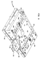
- FIGURE 5 is a rear bottom perspective view of the basic telephone with the key expansion interconnect bracket installed into the base of a basic telephone.
- FIGURE 6 is a perspective view of the key expansion option module.
- FIGURE 7 is a bottom perspective view of the key expansion option module connected to the basic telephone with the key expansion option interconnect bracket.
- Figures 1 and 2 illustrate different perspective views of key expansion option interconnect bracket 100.
- Figure 3 illustrates a side view of key expansion option interconnect bracket 100.
- the key expansion option interconnect bracket 100 is preferably a single piece made of injection molded lightweight plastic.
- the key expansion option module bracket 100 performs two functions: (1) it provides the necessary electrical connections between the basic telephone 200 and the key expansion option module 300, and (2) it provides the mechanical support necessary to secure the key expansion option module 300 to the basic telephone 200.
- bracket 100 has a main unit tab 102 on one end and a module tab 104 on the opposite end.
- Multiple traces (example trace 106 is shown in Figure 2) run along the surface 125 of of key expansion option interconnect bracket 100.
- the traces terminate on one side at the main unit tab 102 and on the other side at module tab 104.
- the other traces appear on the surface of bracket 100 in a similar manner. Traces are raised electrical contacts which carry signals received at one tab and transfer the signal to the other tab.
- Main unit tab 102 also contains a stopping edge 110 on main unit tab 102 on the side opposite the side on which the traces terminate. Any number of traces may be used, depending on the communication requirements of the main unit and auxiliary device. If a very large number of communication channels is required, traces may also be run along the surface opposite surface 125.
- Main unit tab 102 is connected to a main unit bracket 116.
- Main unit bracket 116 has two sections, a tab extension 118 and an elevator member 120.
- Tab extension 118 extends from the elevator member 120 and is connected to main unit tab 102.
- Tab extension 118 also contains fastening holes 130 and 132.
- a coupling bracket 122 is connected to elevator member 120 at the end opposite to tab extension 118.
- Coupling bracket 122 has a riser 124 connected to it on its end opposite to the main unit bracket 116.
- Riser 124 connects module tab 104 to the main body of the bracket 122 and elevates the module tab 104 above the surface 125 of the coupling bracket 122 a height H1.
- Coupling bracket 122 has a guide 126 on one side and a second guide 128 on an opposite side as shown in Figures 1 through 3.
- Guides 126 and 128 extend the length of the coupling bracket 122 from its connection to the main unit bracket 116 to the riser 124.
- the guides 126 and 128 extend above surface 125 of the coupling member 122 to height H2.
- a snap-connector aperture 134 is located near the center of coupling member 122.
- Basic telephone 200 has a base 202 with a bottom surface 204.
- the basic telephone 200 has two option module bays 206 and 208 on the bottom surface 204 of the base 202.
- the base 202 of basic telephone 200 also has a bracket receiving recess 210 (partially obscured in Figure 4 by tab extension 118) which includes a tab receiving slot 220 at one end.
- the bracket receiving recess 210 and tab receiving slot 220 are configured to receive tab extension 118 and main unit tab 102 such that the exposed surface of tab extension 118 is substantially flush with the bottom surface of option module bay 208.
- the base 202 of basic telephone 200 has a side wall 216 which has an outside surface 212 and an inside surface 214.
- the inside surface 214 has a recessed area 218 to receive elevator member 120 such that the outer surface 123 (see Figure 3) of the elevator member 120 is substantially flush with the inner surface 214 of side wall 216.
- the bracket receiving recess 210, tab receiving slot 220 and the recessed area 218 together cooperate to prevent the key expansion option bracket 100 from interfering with the installation or operation of modules installed in option module bay 208.
- the main module bracket 116 is completely recessed into the bottom surface 204 of the base 202 and the inner surface 214 of side wall 216.
- a connector (not shown) is recessed within the tab receiving slot 220.
- the connector is configured to create an electrical connection with the traces on main unit tab 102.
- any type of connector which is compatible with the main unit tab 102 with raised traces may be used.
- the angle at which the tab extension 118 is connected to the elevator member 120 of bracket 100 is determined by the angle which exists between the inner surface 214 and the bottom surface of the option module bay 208.
- the thickness of side wall 216 at the recessed area 218 is approximately equal to distance D1 (see Figure 3) between guides 126, 128 and elevator member 120. The correspondence in dimensions insures that the bracket 100 fits snugly around the side wall 216. This prevents the bracket 100 from twisting or bending, causing damage to the connectors in either the basic telephone 200 or the key expansion option module 300.
- the interconnect bracket can be permanently or removably attached to the main unit.
- the key expansion option module interconnect bracket 100 is secured to the basic telephone 200 by screws. These screws go through the fastening holes 130 and 132 and are received by holes in recess 210 which are threaded during screw installation.
- screws go through the fastening holes 130 and 132 and are received by holes in recess 210 which are threaded during screw installation.
- other permanent or removable fastening devices could also be utilized.
- a key expansion option module 300 is illustrated.
- Key expansion option module 300 has an aperture 302 on a side 312.
- the side 312 of key expansion option module 300 is nearly flush with and immediately adjacent to outer surface 212 of basic telephone side wall 216 as shown in Figure 7.
- Aperture 302 is configured to receive coupling member 122 of bracket 100.
- Aperture 302 has two guide receiving portions 306 and 308 which are configured to receive the guides 128 and 126, respectively.
- Aperture 302 also has a tab receiving portion 304 for receiving module tab 104.
- the height, shown as dimension H3, of the guide receiving portions 306 and 308 should be approximately equal to the height, shown as dimension H2, that guides 126 and 128 rise above the surface of the coupling member 122. It is also necessary that the height, shown as dimension H4 of the tab receiving portion 304 be approximately equal to the height, shown as dimension H1, that module tab 104 is above the surface of coupling member 122.
- An internal connector (not shown) is recessed within the aperture 302.
- the connector is configured to receive and make electrical connection with module tab 104.
- any type of connector which is compatible to the module tab 104 with raised traces may be used.
- the height of the guide receiving portions 306 and 308 and the tab receiving portion 304 limit the angle at which the coupling member 122 is inserted into the aperture 302. This insures that once the coupling member 122 is inserted into the aperture 302, it is self-guided.
- the module tab 104 connects with the connector internal to the key expansion option module 300.
- the guide members 126 and 128 extend a substantial portion of the length of coupling member 122.
- the length of guides 126 and 128 only need to be as long as is necessary to insure that the module tab 104 aligns with the internal connector (not shown) in the key expansion option module when the coupling member is installed in aperture 302.
- the key expansion option module 300 has a snapping connector 310.
- the upper surface of the snapping connector 310 has a raised portion (not shown) corresponding in shape and size to snap-connector aperture 134.
- the snap connector 310 is configured to release when subjected to forces such as would be experienced if the coupled units were dropped. When the basic telephone 200 unit and the key expansion option module 300 come apart, they distribute the force of the drop between them, thus reducing the total shock to their components.
- the interconnect bracket mechanically and electrically connects a key expansion option module to a basic telephone.
- this invention may be used in other applications which require both a sturdy mechanical attachment and an electrical connection between a main module and an auxiliary device.
- the present invention may be used to connect additional disk drives as well as accessories to a computer, audio/visual components connected together, or automatic controllers and timers could be added onto household appliances.
Landscapes
- Engineering & Computer Science (AREA)
- Signal Processing (AREA)
- Telephone Set Structure (AREA)
Description
- This invention relates generally to electrical connectors and, more particularly, to support brackets for upgrade expansion modules which incorporate electrical connectors.
- Conventional telephone model product lines typically include a basic telephone which contains the most basic and common features desired and used by the telephone user. In addition to these basic functions, a basic telephone may need to perform additional functions which a customer may need or desire. These are typically referred to as upgrade features. Examples of such upgrade features include adding a speaker, encryption or decryption of the voice message, adding a headset to the telephone, or interfacing the basic telephone to a recording device to record voice messages. Typically, these upgrade features require function keys or push buttons to enable the user to provide input and control.
- One conventional technique used to provide additional function keys has been to create a new, larger telephone with a larger surface area than the basic telephone. The larger surface area will then support the basic function keys as well as the additional keys associated with the upgrade feature. This technique has proven to be uneconomical due to the cost of designing and maintaining multiple model product lines of telephones, including a product line with basic features as well as other product lines with specific upgrade features. This technique has also resulted in additional costs to support trained service personnel to install the new models with the upgrade features at the customer's site.
- Another conventional technique has been to add an expansion module containing the additional function keys to the basic telephone. An expansion module which contains additional function keys is referred to as a key expansion option (KEO) module. One conventional method for adding a KEO module to a basic telephone is to attach a piece of sheet metal to the bottom of the basic telephone and then attach the KEO module to the same piece of sheet metal. Electrical connections between the KEO module and the basic telephone are provided via a cable assembly (see e.g. TELCOM REPORT, vol. 5, NO. 5, October 1982, PASSAU, BRD, pages 298-302). A disadvantage of this technique is the increased cost of additional parts and assembly. In addition, the bottom surface of the basic telephone must be dedicated to this KEO module attachment, thereby limiting the additional features which can be added to the basic telephone. Also, the weight of the entire telephone is significantly increased, leading to more component failures if the telephone is dropped. There is a need for a coupling mechanism, for connecting a KEO module to a basic telephone which is user installable and cosmetically appealing. There should not be, for example, visible wires nor dangling cables connecting the KEO module and the basic telephone. The basic telephone should not have connectors visible to the user when no KEO module is installed. Also, the attachment means should be light in weight in order to avoid damage to the basic telephone or KEO module components should the telephone be dropped.
- This invention provides an interconnect bracket as defined in claims 1, 14 and 18, respectively, to connect an auxiliary device to a main unit. In the preferred embodiment of the present invention, the main unit is a basic telephone and the auxiliary unit is a key expansion option module. The interconnect bracket provides the necessary electrical connections between the basic telephone and the key expansion option module and provides the mechanical support necessary to secure the key expansion option module to the basic telephone. As a result, very few additional parts are required.
- The interconnect bracket provides the electrical connection in the preferred embodiment by employing traces which run the length of the bracket. The interconnect bracket attaches to the bottom surface of the main unit and is configured to fit within receiving recess slots such that the bracket is substantially flush with the bottom surface of the basic telephone. The interconnect bracket contains guides which assist in the installation of the auxiliary device and provides a means of connection with the key expansion option module which enables the device to separate from the basic telephone should the combined unit be dropped. The interconnect bracket is user installable and requires minimal tools. Since the interconnect bracket attaches to the base of the main unit, no visible connectors are required on the main unit. The interconnect bracket also electrically connects the main unit with the auxiliary device. Therefore, no cables or wires are necessary. The interconnect bracket snaps into the key expansion option module in such a manner that it releases when it is subjected to forces such as would be experienced if the coupled units were dropped. This reduces the potential for damage to the components of the basic telephone and key expansion option module.
- The foregoing and other features and examples of the invention will be apparent from the following more particular description of preferred embodiments of the invention as illustrated in the accompanying drawings in which:
- FIGURE 1 is a perspective view of the key expansion option interconnect bracket with the main unit bracket elevated.
- FIGURE 2 is a perspective view of the key expansion option interconnect bracket illustrating a trace element which terminates on both connectors.
- FIGURE 3 is a side view of the key expansion option interconnect bracket.
- FIGURE 4 is a front bottom perspective view of the basic telephone with the key expansion interconnect bracket installed in the base of a basic telephone.
- FIGURE 5 is a rear bottom perspective view of the basic telephone with the key expansion interconnect bracket installed into the base of a basic telephone.
- FIGURE 6 is a perspective view of the key expansion option module.
- FIGURE 7 is a bottom perspective view of the key expansion option module connected to the basic telephone with the key expansion option interconnect bracket.
- The preferred embodiment of the present invention will now be described with reference to Figures 1-7, where like reference numbers refer to like elements.
- Figures 1 and 2 illustrate different perspective views of key expansion option interconnect
bracket 100. Figure 3 illustrates a side view of key expansionoption interconnect bracket 100. The key expansionoption interconnect bracket 100 is preferably a single piece made of injection molded lightweight plastic. The key expansionoption module bracket 100 performs two functions: (1) it provides the necessary electrical connections between thebasic telephone 200 and the keyexpansion option module 300, and (2) it provides the mechanical support necessary to secure the keyexpansion option module 300 to thebasic telephone 200. - Referring to Figures 1 through 3,
bracket 100 has amain unit tab 102 on one end and amodule tab 104 on the opposite end. Multiple traces (example trace 106 is shown in Figure 2) run along thesurface 125 of of key expansionoption interconnect bracket 100. The traces terminate on one side at themain unit tab 102 and on the other side atmodule tab 104. For clarity, only asingle trace element 106 is illustrated in its entirety. The other traces appear on the surface ofbracket 100 in a similar manner. Traces are raised electrical contacts which carry signals received at one tab and transfer the signal to the other tab.Main unit tab 102 also contains astopping edge 110 onmain unit tab 102 on the side opposite the side on which the traces terminate. Any number of traces may be used, depending on the communication requirements of the main unit and auxiliary device. If a very large number of communication channels is required, traces may also be run along the surfaceopposite surface 125. - The
main unit tab 102 is connected to amain unit bracket 116.Main unit bracket 116 has two sections, atab extension 118 and anelevator member 120.Tab extension 118 extends from theelevator member 120 and is connected tomain unit tab 102.Tab extension 118 also contains fastening holes 130 and 132. - A
coupling bracket 122 is connected toelevator member 120 at the end opposite totab extension 118.Coupling bracket 122 has ariser 124 connected to it on its end opposite to themain unit bracket 116.Riser 124 connectsmodule tab 104 to the main body of thebracket 122 and elevates themodule tab 104 above thesurface 125 of the coupling bracket 122 a height H1. -
Coupling bracket 122 has aguide 126 on one side and asecond guide 128 on an opposite side as shown in Figures 1 through 3.Guides coupling bracket 122 from its connection to themain unit bracket 116 to theriser 124. Theguides surface 125 of thecoupling member 122 to height H2. A snap-connector aperture 134 is located near the center ofcoupling member 122. - Referring to Figures 4 and 5, a bottom perspective view of a main unit, shown here as
basic telephone 200, is illustrated.Basic telephone 200 has a base 202 with abottom surface 204. Thebasic telephone 200 has twooption module bays bottom surface 204 of thebase 202. Thebase 202 ofbasic telephone 200 also has a bracket receiving recess 210 (partially obscured in Figure 4 by tab extension 118) which includes atab receiving slot 220 at one end. Thebracket receiving recess 210 andtab receiving slot 220 are configured to receivetab extension 118 andmain unit tab 102 such that the exposed surface oftab extension 118 is substantially flush with the bottom surface ofoption module bay 208. - The
base 202 ofbasic telephone 200 has aside wall 216 which has anoutside surface 212 and aninside surface 214. Theinside surface 214 has a recessedarea 218 to receiveelevator member 120 such that the outer surface 123 (see Figure 3) of theelevator member 120 is substantially flush with theinner surface 214 ofside wall 216. - The
bracket receiving recess 210,tab receiving slot 220 and the recessedarea 218 together cooperate to prevent the keyexpansion option bracket 100 from interfering with the installation or operation of modules installed inoption module bay 208. When the key expansion option bracket is installed in thebasic telephone 200, themain module bracket 116 is completely recessed into thebottom surface 204 of thebase 202 and theinner surface 214 ofside wall 216. - A connector (not shown) is recessed within the
tab receiving slot 220. In the preferred embodiment of the present invention, the connector is configured to create an electrical connection with the traces onmain unit tab 102. However, one should know that any type of connector which is compatible with themain unit tab 102 with raised traces may be used. - The angle at which the
tab extension 118 is connected to theelevator member 120 ofbracket 100 is determined by the angle which exists between theinner surface 214 and the bottom surface of theoption module bay 208. In addition, the thickness ofside wall 216 at the recessedarea 218 is approximately equal to distance D1 (see Figure 3) betweenguides elevator member 120. The correspondence in dimensions insures that thebracket 100 fits snugly around theside wall 216. This prevents thebracket 100 from twisting or bending, causing damage to the connectors in either thebasic telephone 200 or the keyexpansion option module 300. - The interconnect bracket can be permanently or removably attached to the main unit. In the preferred embodiment of the present invention, the key expansion option
module interconnect bracket 100 is secured to thebasic telephone 200 by screws. These screws go through the fastening holes 130 and 132 and are received by holes inrecess 210 which are threaded during screw installation. However, one should know that other permanent or removable fastening devices could also be utilized. - Referring to Figure 6, the auxiliary unit, in the preferred embodiment, a key
expansion option module 300 is illustrated. Keyexpansion option module 300 has anaperture 302 on aside 312. When the keyexpansion option module 300 is connected to thebasic telephone 200, theside 312 of keyexpansion option module 300 is nearly flush with and immediately adjacent toouter surface 212 of basictelephone side wall 216 as shown in Figure 7. -
Aperture 302 is configured to receivecoupling member 122 ofbracket 100.Aperture 302 has twoguide receiving portions guides Aperture 302 also has atab receiving portion 304 for receivingmodule tab 104. The height, shown as dimension H3, of theguide receiving portions coupling member 122. It is also necessary that the height, shown as dimension H4 of thetab receiving portion 304 be approximately equal to the height, shown as dimension H1, thatmodule tab 104 is above the surface ofcoupling member 122. - An internal connector (not shown) is recessed within the
aperture 302. In the preferred embodiment of the present invention, the connector is configured to receive and make electrical connection withmodule tab 104. However, one should know that any type of connector which is compatible to themodule tab 104 with raised traces may be used. - The height of the
guide receiving portions tab receiving portion 304 limit the angle at which thecoupling member 122 is inserted into theaperture 302. This insures that once thecoupling member 122 is inserted into theaperture 302, it is self-guided. Themodule tab 104 connects with the connector internal to the keyexpansion option module 300. In the preferred embodiment of the present invention, theguide members coupling member 122. However, the length ofguides module tab 104 aligns with the internal connector (not shown) in the key expansion option module when the coupling member is installed inaperture 302. - The key
expansion option module 300 has a snappingconnector 310. The upper surface of the snappingconnector 310 has a raised portion (not shown) corresponding in shape and size to snap-connector aperture 134. Thesnap connector 310 is configured to release when subjected to forces such as would be experienced if the coupled units were dropped. When thebasic telephone 200 unit and the keyexpansion option module 300 come apart, they distribute the force of the drop between them, thus reducing the total shock to their components. - In the preferred embodiment of the present invention the interconnect bracket mechanically and electrically connects a key expansion option module to a basic telephone. However, one should know that this invention may be used in other applications which require both a sturdy mechanical attachment and an electrical connection between a main module and an auxiliary device. For example, the present invention may be used to connect additional disk drives as well as accessories to a computer, audio/visual components connected together, or automatic controllers and timers could be added onto household appliances.
- While the invention has been particularly shown and described with reference to a preferred embodiment thereof, it will be understood by those skilled in the art that various changes in form and details may be made therein without departing from the scope of the invention as defined in the appended claims.
Claims (18)
- An interconnect bracket which mechanically and electrically connects an auxiliary device (300) having an aperture (302) with a guide receiving portion (306,308) and a tab receiving portion (304), a snap-connector (310), and an internal auxiliary connector accessible through the aperture, with a main unit (200) having a base (202) with a bottom surface (204) and a side wall (216) with an inner surface (214) adjacent to the bottom surface, a recessed area (218) within the bottom surface and the inner surface, and an internal main connector within the recessed area, said interconnect bracket comprising:a main unit connector (102) configured to be electrically connectable to the internal main connector;a main unit bracket (116) connected to said main unit connector;a coupling member (122) connected to said main unit bracket on a side opposite to said main unit connector;an auxiliary device connector (104) connected to said coupling member on a side opposite to said main unit bracket and configured to be electrically connectable to the internal auxiliary connectors; and electrical connection means (106) between said main unit connector (102) and said auxiliary device connector (104).
- The interconnect bracket of claim 1, wherein said electrical connection means comprises:
a plurality of traces (106) extending from said main unit connector to said auxiliary device connector and electrically coupling said main unit connector with said auxiliary device connector. - The interconnect bracket of claim 2, wherein said main unit bracket further comprises a plurality of fastening holes (130,132).
- The interconnect bracket of claim 3, wherein said coupling member further comprises:
a snap-connector aperture (134) configured to removably mate with the snap-connector (310) in the auxiliary unit. - The interconnect bracket of claim 4, wherein said coupling member further comprises:
a guide (126,128) extending from said coupling member and configured to be received by the guide receiving portion (306,308) of the aperture (302) in the auxiliary device, whereby said guide and guide receiving portion cooperate to align said auxiliary device connector (104) with the internal auxiliary connector. - The interconnect bracket of claim 5, wherein said coupling member further comprises a riser (124) connected to said coupling member on a side opposite said main unit bracket and connected to said auxiliary device connector.
- The interconnect bracket of claim 6, wherein said riser is configured to position said auxiliary device connector in alignment with the internal auxiliary connector in the aperture (302).
- The interconnect bracket of claim 7, wherein said main unit bracket (116) is adapted to fit within the recessed area (218) in the main unit and to position said main unit connector in electrical connection with the internal main connector.
- The interconnect bracket of claim 8, wherein said guide extends substantially from said auxiliary device connector to said main unit bracket.
- The interconnect bracket of claim 9, wherein said auxiliary device connector is a tab.
- The interconnect bracket of claim 10, wherein said main unit connector is a tab.
- The interconnect bracket of claim 11, wherein the main unit is a basic telephone.
- The interconnect bracket of claim 12, wherein said auxiliary unit comprises a key expansion option module.
- An interconnect bracket which mechanically and electrically connects an auxiliary device having an aperture with a guide receiving portion and a tab receiving portion, a side containing the aperture, a snapping connector, and an internal auxiliary connector accessible through the aperture, with a main unit having a base with a bottom surface and a side with an inner surface adjacent to the bottom surface, a recessed area within the bottom surface and inner surface, and an internal main connector within the recessed area, said interconnect bracket comprising:electrical coupling means (102,104,106) for electrically coupling the main unit with the auxiliary device;main unit bracket means for fitting within the recessed area in the base and side of the main unit and for securing said interconnect bracket to the main unit; andcoupling member bracket means connected to said main unit bracket means, for connecting the auxiliary device to the main unit such that a side of the auxiliary device is adjacent to a side of the main unit.
- The interconnect bracket of claim 14, wherein said electrical coupling means comprises:first electrical connection means (102) for electrically connecting said interconnect bracket with the internal main connector; andsecond electrical connection means (104) for electrically connecting said interconnect bracket with the internal auxiliary connector.
- The interconnect bracket of claim 15, wherein said electrical coupling means further comprises:electrical transfer means (106) for transferring electrical signals between said first electrical connection means and said second electrical connection means; andguide means (126,128) for guiding said second electrical connection means into the internal auxiliary connector.
- The interconnect bracket of claim 16, wherein said coupling member bracket means further comprises:
connector means (310) for mechanically connecting the auxiliary device to said coupling member means, said connector means releasing the auxiliary device when subjected to an impact. - An interconnect bracket which mechanically and electrically connects an auxiliary device having an aperture with a guide receiving portion and a tab receiving portion, a snap-connector, and an internal auxiliary connector accessible through the aperture, with a main unit having a base with a bottom surface and a side wall with an inner surface adjacent to the bottom surface, a recessed area within the bottom surface and the inner surface, and an internal main connector within the recessed area, said interconnect bracket comprising:a main unit connector configured to be electrically connectable to the internal main connector;a main unit bracket having a plurality of fastening holes, said main unit bracket connected to said main unit connector,a coupling member connected to said main unit bracket on a side opposite to said main unit connector, and havinga snap-connector aperture configured to removably mate with the snap-connector in the auxiliary unit, anda guide extending from said coupling member and configured to be received by the guide receiving portion of the aperture, whereby said guide and guide receiving portion cooperate to align an auxiliary device connector with the internal auxiliary connector;said auxiliary device connector connected to said coupling member on a side opposite said main unit bracket, said auxiliary device connector configured to be electrically connectable to the internal auxiliary connector; anda plurality of traces on the interconnect bracket extending from said main unit connector to said auxiliary device connector and electrically coupling said main unit connector with said auxiliary device connector.
Applications Claiming Priority (2)
| Application Number | Priority Date | Filing Date | Title |
|---|---|---|---|
| US90358392A | 1992-06-25 | 1992-06-25 | |
| US903583 | 1992-06-25 |
Publications (3)
| Publication Number | Publication Date |
|---|---|
| EP0575760A2 EP0575760A2 (en) | 1993-12-29 |
| EP0575760A3 EP0575760A3 (en) | 1995-04-05 |
| EP0575760B1 true EP0575760B1 (en) | 1997-07-23 |
Family
ID=25417729
Family Applications (1)
| Application Number | Title | Priority Date | Filing Date |
|---|---|---|---|
| EP93108382A Expired - Lifetime EP0575760B1 (en) | 1992-06-25 | 1993-05-24 | Apparatus for electrically and mechanically connecting an auxiliary device to a main unit |
Country Status (4)
| Country | Link |
|---|---|
| US (1) | US5414768A (en) |
| EP (1) | EP0575760B1 (en) |
| JP (1) | JP3407932B2 (en) |
| DE (1) | DE69312398T2 (en) |
Families Citing this family (6)
| Publication number | Priority date | Publication date | Assignee | Title |
|---|---|---|---|---|
| US5889859A (en) * | 1996-05-31 | 1999-03-30 | Motorola, Inc. | Modular housing system |
| US6038314A (en) * | 1998-02-23 | 2000-03-14 | Nortel Networks Corporation | Plug-in accessories |
| DE10053209A1 (en) * | 2000-10-26 | 2002-08-01 | Siemens Ag | Display adapter for comfort telephones |
| US7190786B2 (en) * | 2001-09-28 | 2007-03-13 | Bellsouth Intellectual Property Corp. | Telephone with removable DSL cartridge |
| US20080179408A1 (en) * | 2007-01-30 | 2008-07-31 | Johnson Controls Technology Company | Sensor-free optimal control of air-side economizer |
| JP7849066B2 (en) * | 2024-09-11 | 2026-04-21 | Necプラットフォームズ株式会社 | Side option coupling mechanism and assembly method for communication equipment |
Family Cites Families (5)
| Publication number | Priority date | Publication date | Assignee | Title |
|---|---|---|---|---|
| US4061888A (en) * | 1976-08-12 | 1977-12-06 | Crest Industries, Inc. | Control unit mounting and interconnecting apparatus for telephone sets |
| US4549776A (en) * | 1984-04-16 | 1985-10-29 | Northern Telecom Limited | Connecting member for connecting two communications terminal units |
| DE3607727A1 (en) * | 1986-01-25 | 1987-09-03 | Telefonbau & Normalzeit Gmbh | TELEPHONE SET |
| US4739451A (en) * | 1986-12-31 | 1988-04-19 | Wang Laboratories, Inc. | Modularly expandable desktop keyboard |
| JPH0756529Y2 (en) * | 1989-10-21 | 1995-12-25 | 株式会社東芝 | Desktop / wall-mounted phone |
-
1993
- 1993-05-24 DE DE69312398T patent/DE69312398T2/en not_active Expired - Fee Related
- 1993-05-24 EP EP93108382A patent/EP0575760B1/en not_active Expired - Lifetime
- 1993-06-25 JP JP15538193A patent/JP3407932B2/en not_active Expired - Fee Related
-
1994
- 1994-05-12 US US08/241,952 patent/US5414768A/en not_active Expired - Lifetime
Also Published As
| Publication number | Publication date |
|---|---|
| EP0575760A3 (en) | 1995-04-05 |
| DE69312398D1 (en) | 1997-08-28 |
| JPH06104967A (en) | 1994-04-15 |
| EP0575760A2 (en) | 1993-12-29 |
| DE69312398T2 (en) | 1998-01-15 |
| US5414768A (en) | 1995-05-09 |
| JP3407932B2 (en) | 2003-05-19 |
Similar Documents
| Publication | Publication Date | Title |
|---|---|---|
| US6854895B2 (en) | Media wall converter and housing | |
| US6457874B1 (en) | Wall mountable mixed media outlet | |
| US6586680B1 (en) | Modular bend radius control fixture | |
| US4432604A (en) | Self-adjusting fiberoptic connector assembly | |
| TWI321877B (en) | Module wall plate mountable within a wall structure, premise wiring system,and method of connecting premise wiring to a wall plate | |
| EP1559277B1 (en) | Network connection sensing module | |
| US6086415A (en) | High density modular patch panel | |
| US5562493A (en) | Network interface assembly and mounting frame | |
| US7979985B2 (en) | Multi-port mounting bracket and method | |
| CA2017589C (en) | Combination power and communication electrical wall terminal | |
| MX2007011251A (en) | Distribution module for an optic fiber distribution hub. | |
| US20050053087A1 (en) | Ethernet converter | |
| US5414768A (en) | Apparatus for electrically and mechanically connecting an auxiliary device to a main unit | |
| US5993251A (en) | Staggered Faceplate | |
| US4678251A (en) | Modular installation system for data cable interfacing | |
| US6991471B2 (en) | Plug-in unit, a housing and an electronic apparatus | |
| US20130129295A1 (en) | Fiber Optic Collector and Terminal Assemblies | |
| US5265186A (en) | Optical fiber distribution apparatus | |
| GB2367378A (en) | Patch panel with main structural part formed on a single plastics moulding | |
| US6646870B2 (en) | Modularized component mounting structure | |
| RU2407225C1 (en) | Set of telecommunications equipment with internal and external frames | |
| EP0575761B1 (en) | User installed telephone option module to provide additional functions to a basic telephone | |
| WO1999048171A1 (en) | Modular network adapter | |
| US6510056B1 (en) | Hinged removable connector module | |
| US6044151A (en) | Apparatus for mounting a low pass filter in a telephone network interface box |
Legal Events
| Date | Code | Title | Description |
|---|---|---|---|
| PUAI | Public reference made under article 153(3) epc to a published international application that has entered the european phase |
Free format text: ORIGINAL CODE: 0009012 |
|
| AK | Designated contracting states |
Kind code of ref document: A2 Designated state(s): DE FR GB |
|
| PUAL | Search report despatched |
Free format text: ORIGINAL CODE: 0009013 |
|
| AK | Designated contracting states |
Kind code of ref document: A3 Designated state(s): DE FR GB |
|
| RAP1 | Party data changed (applicant data changed or rights of an application transferred) |
Owner name: SIEMENS ROLM COMMUNICATIONS INC. (A DELAWARE CORP. |
|
| 17P | Request for examination filed |
Effective date: 19951005 |
|
| GRAG | Despatch of communication of intention to grant |
Free format text: ORIGINAL CODE: EPIDOS AGRA |
|
| 17Q | First examination report despatched |
Effective date: 19961023 |
|
| GRAH | Despatch of communication of intention to grant a patent |
Free format text: ORIGINAL CODE: EPIDOS IGRA |
|
| GRAH | Despatch of communication of intention to grant a patent |
Free format text: ORIGINAL CODE: EPIDOS IGRA |
|
| RAP1 | Party data changed (applicant data changed or rights of an application transferred) |
Owner name: SIEMENS BUSINESS COMMUNICATION SYSTEMS, INC. (A DE |
|
| GRAA | (expected) grant |
Free format text: ORIGINAL CODE: 0009210 |
|
| AK | Designated contracting states |
Kind code of ref document: B1 Designated state(s): DE FR GB |
|
| REF | Corresponds to: |
Ref document number: 69312398 Country of ref document: DE Date of ref document: 19970828 |
|
| ET | Fr: translation filed | ||
| PLBE | No opposition filed within time limit |
Free format text: ORIGINAL CODE: 0009261 |
|
| 26N | No opposition filed | ||
| REG | Reference to a national code |
Ref country code: GB Ref legal event code: IF02 |
|
| PGFP | Annual fee paid to national office [announced via postgrant information from national office to epo] |
Ref country code: GB Payment date: 20060505 Year of fee payment: 14 |
|
| PGFP | Annual fee paid to national office [announced via postgrant information from national office to epo] |
Ref country code: FR Payment date: 20060523 Year of fee payment: 14 |
|
| PGFP | Annual fee paid to national office [announced via postgrant information from national office to epo] |
Ref country code: DE Payment date: 20060724 Year of fee payment: 14 |
|
| GBPC | Gb: european patent ceased through non-payment of renewal fee |
Effective date: 20070524 |
|
| REG | Reference to a national code |
Ref country code: FR Ref legal event code: ST Effective date: 20080131 |
|
| PG25 | Lapsed in a contracting state [announced via postgrant information from national office to epo] |
Ref country code: DE Free format text: LAPSE BECAUSE OF NON-PAYMENT OF DUE FEES Effective date: 20071201 |
|
| PG25 | Lapsed in a contracting state [announced via postgrant information from national office to epo] |
Ref country code: GB Free format text: LAPSE BECAUSE OF NON-PAYMENT OF DUE FEES Effective date: 20070524 |
|
| PG25 | Lapsed in a contracting state [announced via postgrant information from national office to epo] |
Ref country code: FR Free format text: LAPSE BECAUSE OF NON-PAYMENT OF DUE FEES Effective date: 20070531 |