EP0575690B1 - Apparatus for annealing walls of nuclear reactors - Google Patents
Apparatus for annealing walls of nuclear reactors Download PDFInfo
- Publication number
- EP0575690B1 EP0575690B1 EP93100256A EP93100256A EP0575690B1 EP 0575690 B1 EP0575690 B1 EP 0575690B1 EP 93100256 A EP93100256 A EP 93100256A EP 93100256 A EP93100256 A EP 93100256A EP 0575690 B1 EP0575690 B1 EP 0575690B1
- Authority
- EP
- European Patent Office
- Prior art keywords
- steam
- annular space
- nuclear reactor
- core
- reactor
- Prior art date
- Legal status (The legal status is an assumption and is not a legal conclusion. Google has not performed a legal analysis and makes no representation as to the accuracy of the status listed.)
- Expired - Lifetime
Links
- 238000000137 annealing Methods 0.000 title claims description 21
- 239000007789 gas Substances 0.000 description 40
- 238000010438 heat treatment Methods 0.000 description 11
- 238000000034 method Methods 0.000 description 8
- XLYOFNOQVPJJNP-UHFFFAOYSA-N water Substances O XLYOFNOQVPJJNP-UHFFFAOYSA-N 0.000 description 6
- 239000007788 liquid Substances 0.000 description 3
- 239000002184 metal Substances 0.000 description 3
- 230000004048 modification Effects 0.000 description 3
- 238000012986 modification Methods 0.000 description 3
- 238000004891 communication Methods 0.000 description 2
- 239000000463 material Substances 0.000 description 2
- 238000011084 recovery Methods 0.000 description 2
- 230000004075 alteration Effects 0.000 description 1
- 230000000712 assembly Effects 0.000 description 1
- 238000000429 assembly Methods 0.000 description 1
- 238000001816 cooling Methods 0.000 description 1
- 125000004122 cyclic group Chemical group 0.000 description 1
- 230000007812 deficiency Effects 0.000 description 1
- 238000001983 electron spin resonance imaging Methods 0.000 description 1
- 239000000446 fuel Substances 0.000 description 1
- 230000006698 induction Effects 0.000 description 1
- 238000002347 injection Methods 0.000 description 1
- 239000007924 injection Substances 0.000 description 1
- 239000003758 nuclear fuel Substances 0.000 description 1
- 230000003134 recirculating effect Effects 0.000 description 1
- 230000001105 regulatory effect Effects 0.000 description 1
- 230000000284 resting effect Effects 0.000 description 1
- 239000002915 spent fuel radioactive waste Substances 0.000 description 1
Images


Classifications
-
- G—PHYSICS
- G21—NUCLEAR PHYSICS; NUCLEAR ENGINEERING
- G21C—NUCLEAR REACTORS
- G21C19/00—Arrangements for treating, for handling, or for facilitating the handling of, fuel or other materials which are used within the reactor, e.g. within its pressure vessel
-
- G—PHYSICS
- G21—NUCLEAR PHYSICS; NUCLEAR ENGINEERING
- G21C—NUCLEAR REACTORS
- G21C13/00—Pressure vessels; Containment vessels; Containment in general
-
- Y—GENERAL TAGGING OF NEW TECHNOLOGICAL DEVELOPMENTS; GENERAL TAGGING OF CROSS-SECTIONAL TECHNOLOGIES SPANNING OVER SEVERAL SECTIONS OF THE IPC; TECHNICAL SUBJECTS COVERED BY FORMER USPC CROSS-REFERENCE ART COLLECTIONS [XRACs] AND DIGESTS
- Y02—TECHNOLOGIES OR APPLICATIONS FOR MITIGATION OR ADAPTATION AGAINST CLIMATE CHANGE
- Y02E—REDUCTION OF GREENHOUSE GAS [GHG] EMISSIONS, RELATED TO ENERGY GENERATION, TRANSMISSION OR DISTRIBUTION
- Y02E30/00—Energy generation of nuclear origin
- Y02E30/30—Nuclear fission reactors
Definitions
- This invention relates to apparatus suitable for annealing the interior walls of a nuclear reactor, particularly the vertical walls thereof, including the weld material in said walls, said apparatus comprising the features as recited in the preamble of claim 1.
- An apparatus of the kind defined in the preamble of claim 1 and being disclosed by FR-A-2 442 891 suffers from similar deficiencies as the beforementioned Russian system, since not only heating elements but also a space consuming convection chamber with deviating means for heating gases have to be incorporated in the reactor shell, leading to a substantial weight of the apparatus.
- an apparatus suitable for annealing the interior walls of a nuclear reactor which comprises a nuclear reactor shell, a cap securely attached thereto, said cap having a high-energy steam inlet extending inwardly therein and a low-energy steam outlet extending outwardly therefrom, means defining an annular space adjacent the vertical walls of said reactor through which steam can flow and means for directing low-energy steam to said low-energy steam outlet.
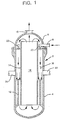
- reference numeral 2 refers to the novel apparatus defined and claimed herein comprising a nuclear reactor shell 4 and cap 6, replacing the normal reactor head, securely attached to nuclear reactor shell 4, by any suitable means, for example, using bolts, therefor.
- Cap 6 is provided with at least one high-energy (that is, high pressure) inlet line 8, preferably a large number, circumferentially spaced within cap 6, and at least one low-energy (that is, low pressure) outlet line 10.
- the fuel supports and water normally present in a nuclear reactor have been removed, but the thermal shield 12 has not. If desired, however, the thermal shield can also be removed, for its presence does not appreciably alter the functional validity of the novel apparatus.
- the apparatus is provided with a shell 14, preferably cylindrical, that together with the adjacent inner wall of nuclear reactor shell 4 defines an annular space 16 that permits flow of gas in the form of steam therethrough in contact with practically all of inner wall of said nuclear reactor shell 4.
- the cylindrical shell 14 can be mounted (by any conventional means, not shown) to the cap 6, the nuclear reactor shell 4, or both, in a manner such that the desired gas flow is not impeded or altered in annular space 16, shell core 18 or therebetween.
- the apparatus shown in Figure 1 is assembled as follows.
- the reactor that is to be subjected to the annealing process is shut down, drained of its liquid water content, and the reactor head, the reactor fuel, the reactor core structure and the thermal shield, if desired, removed therefrom following, for example, standard refueling procedures.
- the cap 6 is then securely attached to nuclear reactor shell 4.
- the first stage requires heating the reactor walls to a temperature of about 454°C (850°F) gradually over a period of time, for example, by introducing a hot gas in the form of steam into the reactor by inlet line 8, circulating the hot gas through the reactor, introducing additional hot gas to maintain the desired temperature therein and removing an approximately equal amount of gas from outlet line 10 to that introduced in inlet line 8 for maintaining the temperature therein.
- Heating to the desired annealing temperature is preferably done at the rate of about 11°C (20°) to about 28°C (50°F) per hour.
- the hot gas in the form of steam is then introduced into apparatus 2 by means of inlet line 8 at a temperature of about 454°C (850°) to about 482°C (900°F) and a pressure of about 7 bar (100) to about 70 bar (1000 psig) and is passed downwardly through annular space 16.
- Injection of said high-pressure gas into the reactor provides sufficient energy to maintain circulation of the gas in the annular space at a rate of about 18,3 m (60) to about 45,7 m (150 feet) per second.
- the gas from inlet line 8 is distributed through a header 20 into the annular space 16.
- the annular space 16 has a width of about 76 mm (three) to about 203 mm (eight inches).
- the hot gases move downwardly and then upwardly through shell core 18 having a diameter of about 2,7 m (nine) to about 3,7 m (12 feet). Most of the gases moving upwardly are recycled and mixed with incoming gases from line 8 before they pass downwardly through annular space 16.
- the incoming gas helps maintain the desired temperature in the reactor.
- the amount of gas leaving outlet 10 is approximately equal to the incoming gas in line 8. No appreciable loss of circulating gas occurs through inlet/outlet lines 22 and 24 present in nuclear reactor shell 4, because the pressure in said lines is approximately the same as the pressure in the annular space 16.
- the length of the cylindrical shell 14 is approximately equal to the vertical dimension of the nuclear reactor shell and the vertical portion of cap 6.
- the temperature of the gas in the reactor during the annealing process is approximately 454°C (850°F), the pressure in the range of about 0 to about 7 bar (100 psig).
- the total amount of gas circulating in the apparatus during steady state operation will amount to about 20 to about 25 tons per hour, and the amount of gas entering and leaving will amount to about 10 to about 25 weight percent thereof.
- annealing operations cease and the nuclear reactor walls will revert substantially to their preirradiated stage.
- the assembly is then brought to ambient temperature and pressure gradually over a period of time in any suitable manner.
- gases or liquid are circulated through the assembly such that cooling from annealing conditions to ambient conditions is carried out at the rate of about 11°C (20°) to about 28°C (50°F) per hour.
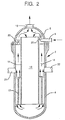
- the novel apparatus illustrated in Figure 2 is similar to that of Figure 1 except that the gases (steam) from header 20 are ejected upwardly to cause circulation of the gases downwardly through shell core 18 and then upwardly through annular space 16 in contact with the adjacent walls of the reactor.
- the apparatus of Figure 3 is similar to those described above in Figures 1 and 2, except that cylindrical shell 14 is not used. Instead, the normal core support assembly 26, comprising an upper core support 28 and a lower core support 30, present in a nuclear reactor, is not removed but is used to help define an annular space 32 adjacent to the walls of the reactor for movement of gas therethrough. In order to so use the core supports 28 and 30, which are cylindrical shells, it is first necessary to raise the core support assembly 26 to permit communication of gas between the annular space 32 between the core support assembly 26 and the space 34 within cap 6.
- FIG. 4 This can be illustrated in Figure 4, wherein normally lower core support 30 is supported in the nuclear reactor 4 by horizontal portion 36 thereof lying on circumferential ledge 38 of nuclear reactor shell 4 and upper core support 28 is supported on horizontal portion 36 by means of horizontal member 40 thereof.
- the core support assembly 26 can be maintained in raised position, for example, using a circumferential assembly 42, preferably split into at least two circumferential parts, comprising a lower circumferential ring 44, an upper circumferential ring 46 and an inclined connecting member 48 provided with sufficient openings 50 to permit movement of gas therethrough, positioned between the core support assembly 26 and circumferential ledge 38, thereby permitting communication between space 34 in cap 6 and annular space 32.
- a circular plate 52 Resting on horizontal position 40 is a circular plate 52 provided with sufficient openings 54 therein in which there are preferably disposed eductors, preferably of a venturi type 56 into which inlet lines 8 can discharge gases therethrough.
- the lower core support 30 has openings 60 communicating with inlet-outlet lines 22 and 24 and with openings 58 in upper core support 28 to permit flow of gases therethrough.
- upper and lower core supports 28 and 30, respectively are rotated, relative to each other, until openings 60 and 58 are no longer in aligned position.
- high energy gas steam
- eductors 56 when used, into core space 62 and then upwardly through annular space 32.
- a large amount of the gases is recycled through eductor 56 and a portion thereof, substantially equivalent to the amount of gases introduced in line 8, is removed from the system through line 10. This flow is continued, for example, for 168 hours while maintaining the temperature of the reactor wall at about 454°C (850°F).
- the novel apparatus illustrated in Figure 5 is similar to that described in Figures 3 and 4 except that the incoming gases (steam) in line 8 are initially directed upwardly into space 34 in cap 6, downwardly through annular space 32, upwardly through core space 62, recirculating a larger portion of the gases and then removing a smaller portion thereof through outlet line 10.
- the hot gases are at a temperature of 454°C (850°F), and above, if needed, are maintained in uniform contact with the walls of the reactor, the walls are uniformly and completely heated to the desired temperature, resulting in reactor walls that are substantially returned to their normal, preirradiated state.
- the gases leaving the eductor in admixture with recycled gas have a temperature of about 488°C (910°F) and a pressure of 2,1 bar (30 psig) and are moved through an annular space having an average width of 152 mm (six inches) at a rate of about 36,6 m (120 feet) per second and then upwardly through the shell core having a diameter of 3 m (10 feet).
- the circulation rate of gas in the apparatus amounts to about 25 tons, of which about 1/5 is continuously removed from the apparatus through outlet line 10, with a remainder being recycled as shown in Figure 1. This procedure is continued for 168 hours while maintaining the temperature of nuclear reactor shell 4 at 454°C (850°) throughout this period.
Landscapes
- Physics & Mathematics (AREA)
- Engineering & Computer Science (AREA)
- Plasma & Fusion (AREA)
- General Engineering & Computer Science (AREA)
- High Energy & Nuclear Physics (AREA)
- Heat Treatment Of Articles (AREA)
- Processing Of Solid Wastes (AREA)
- Structure Of Emergency Protection For Nuclear Reactors (AREA)
Description
- This invention relates to apparatus suitable for annealing the interior walls of a nuclear reactor, particularly the vertical walls thereof, including the weld material in said walls, said apparatus comprising the features as recited in the preamble of claim 1.
- During the normal operation of a nuclear reactor, fast neutrons emanating from the core of the reactor create irradiation damage in the walls of the reactor, as well as in the weld material, resulting in the embrittlement of the metal, thereby reducing the metal toughness thereof. It is known that some, or all of the irradiated metal, can be restored to its initial, preoperational state by subjecting the same to elevated temperatures, for example, 217°C (423°F) to 343°C (650°F), for about 168 hours. It is known that a "wet" annealing process has been carried out on Belgian nuclear reactors with hot water at a relatively low temperature of about 128°C (262°) to about 343°C (650°F). In Feasibility of and Methodology for Thermal Annealing an Embrittled Reactor Vessel (EPRI NP-2712,
Volume 2, Project 1021-1, Final Report, November 1982, pages S-5 and S-6) it is stated that wet annealing at the relatively low temperatures will result in relatively low recovery of the reactor, but that "dry" thermal annealing, that is, without liquid in the reactor, using spent fuel assemblies, induction heating elements or resistance heating elements at temperatures on the order or about 454°C (850°F) for about 168 hours, recovery of the embrittled walls is on the order of about 80 to about 100 percent. Means for carrying out a dry annealing process of the type described is illustrated in Report on Annealing of the Novovoranezh Unit Reactor Vessel in the USSR prepared by N. M. Cole and T. Fridericks for the U. S. Nuclear Regulatory Commission. On page 15, it is stated that for such purpose, there was used annealing apparatus having a weight of 28.7 tons and carrying 54 heating panels distributed on the periphery thereof. An apparatus of the kind defined in the preamble of claim 1 and being disclosed by FR-A-2 442 891 suffers from similar deficiencies as the beforementioned Russian system, since not only heating elements but also a space consuming convection chamber with deviating means for heating gases have to be incorporated in the reactor shell, leading to a substantial weight of the apparatus. - Using hot water in a nuclear reactor to reach an effective annealing temperature of about 454°C (850°F) is virtually impossible, since the pressure required in the water at such high temperature would be so high as to seriously impair the structural integrity of the reactor walls. Normally, the water temperatures in a nuclear reactor cannot be raised above about 341°C (645°F). Although it is possible to reach an effective annealing temperature of about 454°C (850°F) using heating elements, as illustrated above in the Russian reactor system, all of the reactor, including the thermal shields therein, have first to be removed, the heating assembly is extremely large and expensive and it would be difficult to heat the reactor walls uniformly throughout, because it is likely that some portions of the wall heated by adjacent heating elements would have zones there-between that would not receive as much heat energy as the main heated portions, resulting in nonuniform heating of the walls.
- Using the novel apparatus disclosed herein and defined in claim 1 requires only simple alterations in the reactor to be treated, is simple to operate and will result in reactor walls that have been substantially completely heated to at any desired temperature level, for example, during the preheating stage as well as during the annealing stage.
- We have discovered an apparatus suitable for annealing the interior walls of a nuclear reactor which comprises a nuclear reactor shell, a cap securely attached thereto, said cap having a high-energy steam inlet extending inwardly therein and a low-energy steam outlet extending outwardly therefrom, means defining an annular space adjacent the vertical walls of said reactor through which steam can flow and means for directing low-energy steam to said low-energy steam outlet.
-
- Figure 1 is a schematic drawing of apparatus provided with means defining an annular space adjacent to the reactor walls and means for directing steam downwardly through such annular space;
- Figure 2 is a schematic drawing illustrating a modification of the apparatus of Figure 1 wherein means is shown for directing steam upwardly through the annular space;
- Figure 3 is a schematic drawing showing a further modification of the apparatus herein, wherein the core supports are maintained in the reactor space providing means for directing the flow of steam therein;
- Figure 4 is a schematic drawing of a portion of the embodiment of Figure 3 showing the means used to enable use of the core support for directing flow of steam in the reactor; and
- Figure 5 is a schematic drawing similar to Figure 3 but an embodiment for altering the flow of steam within the reactor.
- Referring to the drawings,
reference numeral 2 refers to the novel apparatus defined and claimed herein comprising anuclear reactor shell 4 andcap 6, replacing the normal reactor head, securely attached tonuclear reactor shell 4, by any suitable means, for example, using bolts, therefor.Cap 6 is provided with at least one high-energy (that is, high pressure)inlet line 8, preferably a large number, circumferentially spaced withincap 6, and at least one low-energy (that is, low pressure)outlet line 10. In the embodiment illustrated in Figure 1, the fuel supports and water normally present in a nuclear reactor have been removed, but thethermal shield 12 has not. If desired, however, the thermal shield can also be removed, for its presence does not appreciably alter the functional validity of the novel apparatus. As shown in Figures 1 and 2, the apparatus is provided with ashell 14, preferably cylindrical, that together with the adjacent inner wall ofnuclear reactor shell 4 defines anannular space 16 that permits flow of gas in the form of steam therethrough in contact with practically all of inner wall of saidnuclear reactor shell 4. Thecylindrical shell 14 can be mounted (by any conventional means, not shown) to thecap 6, thenuclear reactor shell 4, or both, in a manner such that the desired gas flow is not impeded or altered inannular space 16,shell core 18 or therebetween. - The apparatus shown in Figure 1 is assembled as follows. The reactor that is to be subjected to the annealing process is shut down, drained of its liquid water content, and the reactor head, the reactor fuel, the reactor core structure and the thermal shield, if desired, removed therefrom following, for example, standard refueling procedures. The
cap 6 is then securely attached tonuclear reactor shell 4. - In using the apparatus shown in Figure 1, the first stage requires heating the reactor walls to a temperature of about 454°C (850°F) gradually over a period of time, for example, by introducing a hot gas in the form of steam into the reactor by
inlet line 8, circulating the hot gas through the reactor, introducing additional hot gas to maintain the desired temperature therein and removing an approximately equal amount of gas fromoutlet line 10 to that introduced ininlet line 8 for maintaining the temperature therein. Heating to the desired annealing temperature is preferably done at the rate of about 11°C (20°) to about 28°C (50°F) per hour. - During the annealing stage, the hot gas in the form of steam, is then introduced into
apparatus 2 by means ofinlet line 8 at a temperature of about 454°C (850°) to about 482°C (900°F) and a pressure of about 7 bar (100) to about 70 bar (1000 psig) and is passed downwardly throughannular space 16. Injection of said high-pressure gas into the reactor provides sufficient energy to maintain circulation of the gas in the annular space at a rate of about 18,3 m (60) to about 45,7 m (150 feet) per second. In a preferred embodiment, the gas frominlet line 8 is distributed through aheader 20 into theannular space 16. Theannular space 16 has a width of about 76 mm (three) to about 203 mm (eight inches). - The hot gases move downwardly and then upwardly through
shell core 18 having a diameter of about 2,7 m (nine) to about 3,7 m (12 feet). Most of the gases moving upwardly are recycled and mixed with incoming gases fromline 8 before they pass downwardly throughannular space 16. The incoming gas helps maintain the desired temperature in the reactor. The amount ofgas leaving outlet 10 is approximately equal to the incoming gas inline 8. No appreciable loss of circulating gas occurs through inlet/outlet lines nuclear reactor shell 4, because the pressure in said lines is approximately the same as the pressure in theannular space 16. - In order to provide unimpeded cyclic flow of gas in the nuclear reactor, the length of the
cylindrical shell 14 is approximately equal to the vertical dimension of the nuclear reactor shell and the vertical portion ofcap 6. - In a typical apparatus herein, the temperature of the gas in the reactor during the annealing process is approximately 454°C (850°F), the pressure in the range of about 0 to about 7 bar (100 psig). The total amount of gas circulating in the apparatus during steady state operation will amount to about 20 to about 25 tons per hour, and the amount of gas entering and leaving will amount to about 10 to about 25 weight percent thereof. At the end of about 168 hours, annealing operations cease and the nuclear reactor walls will revert substantially to their preirradiated stage.
- The assembly is then brought to ambient temperature and pressure gradually over a period of time in any suitable manner. For example, gases or liquid are circulated through the assembly such that cooling from annealing conditions to ambient conditions is carried out at the rate of about 11°C (20°) to about 28°C (50°F) per hour.
- The novel apparatus illustrated in Figure 2 is similar to that of Figure 1 except that the gases (steam) from
header 20 are ejected upwardly to cause circulation of the gases downwardly throughshell core 18 and then upwardly throughannular space 16 in contact with the adjacent walls of the reactor. - The apparatus of Figure 3 is similar to those described above in Figures 1 and 2, except that
cylindrical shell 14 is not used. Instead, the normalcore support assembly 26, comprising anupper core support 28 and alower core support 30, present in a nuclear reactor, is not removed but is used to help define anannular space 32 adjacent to the walls of the reactor for movement of gas therethrough. In order to so use the core supports 28 and 30, which are cylindrical shells, it is first necessary to raise thecore support assembly 26 to permit communication of gas between theannular space 32 between thecore support assembly 26 and thespace 34 withincap 6. - This can be illustrated in Figure 4, wherein normally
lower core support 30 is supported in thenuclear reactor 4 byhorizontal portion 36 thereof lying oncircumferential ledge 38 ofnuclear reactor shell 4 andupper core support 28 is supported onhorizontal portion 36 by means ofhorizontal member 40 thereof. Thecore support assembly 26 can be maintained in raised position, for example, using acircumferential assembly 42, preferably split into at least two circumferential parts, comprising a lowercircumferential ring 44, an uppercircumferential ring 46 and an inclined connectingmember 48 provided withsufficient openings 50 to permit movement of gas therethrough, positioned between thecore support assembly 26 andcircumferential ledge 38, thereby permitting communication betweenspace 34 incap 6 andannular space 32. - Resting on
horizontal position 40 is acircular plate 52 provided withsufficient openings 54 therein in which there are preferably disposed eductors, preferably of aventuri type 56 into whichinlet lines 8 can discharge gases therethrough. - Normally, as shown in Figure 3, the
lower core support 30 hasopenings 60 communicating with inlet-outlet lines openings 58 inupper core support 28 to permit flow of gases therethrough. In order to substantially reduce bypass flow of gas inannular space 32 through said normally alignedopenings openings - During operation of the apparatus illustrated in Figure 3, high energy gas (steam) is introduced into the
apparatus 2 byline 8, passes downwardly into and througheductors 56, when used, intocore space 62 and then upwardly throughannular space 32. A large amount of the gases is recycled througheductor 56 and a portion thereof, substantially equivalent to the amount of gases introduced inline 8, is removed from the system throughline 10. This flow is continued, for example, for 168 hours while maintaining the temperature of the reactor wall at about 454°C (850°F). - The novel apparatus illustrated in Figure 5 is similar to that described in Figures 3 and 4 except that the incoming gases (steam) in
line 8 are initially directed upwardly intospace 34 incap 6, downwardly throughannular space 32, upwardly throughcore space 62, recirculating a larger portion of the gases and then removing a smaller portion thereof throughoutlet line 10. - Since in each of the embodiments herein, the hot gases are at a temperature of 454°C (850°F), and above, if needed, are maintained in uniform contact with the walls of the reactor, the walls are uniformly and completely heated to the desired temperature, resulting in reactor walls that are substantially returned to their normal, preirradiated state.
- In a typical operation herein, using the apparatus of Figure 1 as an example therefor, and assuming steady state condition during the annealing process, five tons per hour of steam at a temperature of 482°C (900°F) and a pressure of 56 bar (800 psig) are passed through an
inlet pipe 8 having an inner diameter of 152 mm (six inches) through aeductor 56, as shown in Figure 3 having a throat diameter of 76 mm (three inches) and a diffuser outlet diameter of 610 mm (24 inches). After leaving the eductor, the gases leaving the eductor in admixture with recycled gas, have a temperature of about 488°C (910°F) and a pressure of 2,1 bar (30 psig) and are moved through an annular space having an average width of 152 mm (six inches) at a rate of about 36,6 m (120 feet) per second and then upwardly through the shell core having a diameter of 3 m (10 feet). The circulation rate of gas in the apparatus amounts to about 25 tons, of which about 1/5 is continuously removed from the apparatus throughoutlet line 10, with a remainder being recycled as shown in Figure 1. This procedure is continued for 168 hours while maintaining the temperature ofnuclear reactor shell 4 at 454°C (850°) throughout this period. - Obviously, many modifications and variations of the invention, as hereinabove set forth, can be made without departing from the scope thereof, and therefore only such limitations should be imposed as are indicated in the appended claims.
Claims (10)
- Apparatus, suitable for annealing by means of a flow of hot gas the interior walls of a nuclear reactor which comprises a nuclear reactor shell (4) and means defining an annular space (16) adjacent the vertical walls of said reactor shell (4) through which the hot gas can flow, the apparatus being characterized by being adapted to the use of steam as the hot gas, and in that a cap (6), which is securely attached to the reactor shell (4), has at least one high-energy steam inlet (8) extending inwardly therein and a low-energy steam outlet (10) extending outwardly therefrom, said high-energy steam inlet (8) being coupled to an external source of steam for introducing steam into said nuclear reactor shell (4) at a temperature of about 454°C to about 482°C and a pressure of about 7 bar to about 70 bar, and in that means are provided for directing a portion of the steam within the interior of said nuclear reactor shell (4) to said low energy steam outlet (10).
- The apparatus of claim 1 wherein said means for defining said annular space (16) comprises an elongated cylindrical shell (14) vertically disposed in said nuclear reactor and open at the ends thereof, thereby permitting passage of steam through the core thereof.
- The apparatus of claim 2 wherein said high-energy steam inlet extends into a header (20).
- The apparatus of claim 3 wherein said header (20) extends downwardly to inject steam into said annular space (16).
- The apparatus of claim 3 wherein said header extends downwardly to inject steam into said core (18).
- The apparatus of claim 1 wherein said means for defining said annular space comprises a nuclear reactor core support (26).
- The apparatus of claim 6 wherein said core support comprises an upper core support portion (28) thereof having at least one opening (58) in the wall thereof and a lower core support portion (30) thereof having at least one opening (60) in the wall thereof, said openings in said core supports being out of alignment with each other.
- The apparatus of claim 7 wherein said high energy steam inlet extends into an eductor (56).
- The apparatus of claim 8 wherein said eductor injects steam downwardly into said annular space.
- The apparatus of claim 8 wherein said eductor injects steam into said core.
Applications Claiming Priority (2)
| Application Number | Priority Date | Filing Date | Title |
|---|---|---|---|
| US866412 | 1992-04-10 | ||
| US07/866,412 US5185123A (en) | 1992-04-10 | 1992-04-10 | Apparatus for annealing walls of nuclear reactors |
Publications (3)
| Publication Number | Publication Date |
|---|---|
| EP0575690A2 EP0575690A2 (en) | 1993-12-29 |
| EP0575690A3 EP0575690A3 (en) | 1994-05-18 |
| EP0575690B1 true EP0575690B1 (en) | 1997-03-19 |
Family
ID=25347554
Family Applications (1)
| Application Number | Title | Priority Date | Filing Date |
|---|---|---|---|
| EP93100256A Expired - Lifetime EP0575690B1 (en) | 1992-04-10 | 1993-01-11 | Apparatus for annealing walls of nuclear reactors |
Country Status (5)
| Country | Link |
|---|---|
| US (1) | US5185123A (en) |
| EP (1) | EP0575690B1 (en) |
| JP (1) | JPH0675081A (en) |
| DE (1) | DE69308936T2 (en) |
| ES (1) | ES2098565T3 (en) |
Families Citing this family (3)
| Publication number | Priority date | Publication date | Assignee | Title |
|---|---|---|---|---|
| US8721810B2 (en) | 2008-09-18 | 2014-05-13 | The Invention Science Fund I, Llc | System and method for annealing nuclear fission reactor materials |
| US8529713B2 (en) * | 2008-09-18 | 2013-09-10 | The Invention Science Fund I, Llc | System and method for annealing nuclear fission reactor materials |
| US8784726B2 (en) * | 2008-09-18 | 2014-07-22 | Terrapower, Llc | System and method for annealing nuclear fission reactor materials |
Family Cites Families (8)
| Publication number | Priority date | Publication date | Assignee | Title |
|---|---|---|---|---|
| GB2017155B (en) * | 1978-03-20 | 1982-06-03 | Atomic Energy Authority Uk | Treatment ofnuclear reactor vessels |
| CH643300A5 (en) * | 1978-11-30 | 1984-05-30 | Kraftwerk Union Ag | Reactor pressure vessel with a heat treatment device for extending the service life of the pressure vessel |
| GB2128638B (en) * | 1982-10-06 | 1985-09-25 | Cooperheat | Heat treatment method and apparatus |
| GB2131834B (en) * | 1982-12-16 | 1986-03-26 | Cooperheat | Heat treatment method and apparatus |
| US4652423A (en) * | 1984-10-11 | 1987-03-24 | Combustion Engineering, Inc. | Magnetic induced heating for ferritic metal annealing |
| IT1229078B (en) * | 1988-03-16 | 1991-07-18 | Air Liquide | METAL ARTICLES TREATMENT PROCESS AND DEVICE FOR TREATMENT. |
| US5025129A (en) * | 1989-06-19 | 1991-06-18 | The United States Of America As Represented By The Department Of Energy | Reactor vessel annealing system |
| US5116026A (en) * | 1989-06-19 | 1992-05-26 | Westinghouse Electric Corp. | Modular annealing apparatus for in situ reactor vessel annealing and related method of assembly |
-
1992
- 1992-04-10 US US07/866,412 patent/US5185123A/en not_active Expired - Fee Related
-
1993
- 1993-01-11 EP EP93100256A patent/EP0575690B1/en not_active Expired - Lifetime
- 1993-01-11 ES ES93100256T patent/ES2098565T3/en not_active Expired - Lifetime
- 1993-01-11 DE DE69308936T patent/DE69308936T2/en not_active Expired - Fee Related
- 1993-02-25 JP JP5060874A patent/JPH0675081A/en active Pending
Also Published As
| Publication number | Publication date |
|---|---|
| JPH0675081A (en) | 1994-03-18 |
| DE69308936T2 (en) | 1997-06-26 |
| EP0575690A2 (en) | 1993-12-29 |
| DE69308936D1 (en) | 1997-04-24 |
| EP0575690A3 (en) | 1994-05-18 |
| ES2098565T3 (en) | 1997-05-01 |
| US5185123A (en) | 1993-02-09 |
Similar Documents
| Publication | Publication Date | Title |
|---|---|---|
| EP0838077B1 (en) | Thermal insulating barrier providing integrated protection for a nuclear reactor vessel | |
| US3725199A (en) | Nuclear reactor organization and fuel assembly arrangement | |
| US6519308B1 (en) | Corrosion mitigation system for liquid metal nuclear reactors with passive decay heat removal systems | |
| US5406602A (en) | Passive air cooling of liquid metal-cooled reactor with double vessel leak accommodation capability | |
| GB948115A (en) | Improved circulating fuel nuclear reactor | |
| US5513234A (en) | Structural member for nuclear reactor pressure tubes | |
| EP2518732A1 (en) | Nuclear power plant and method of operating it | |
| ES8407234A1 (en) | Radiation shield ring assembly and method of disassembling components of a nuclear steam generator using such assembly | |
| GB1091918A (en) | Improvements in or relating to nuclear reactors | |
| US5185123A (en) | Apparatus for annealing walls of nuclear reactors | |
| US4173060A (en) | System and method for retubing a steam generator | |
| US5325407A (en) | Core barrel and support plate assembly for pressurized water nuclear reactor | |
| US4139603A (en) | Hydrogen-oxygen recombiner | |
| US5093075A (en) | Upper internal nuclear reactor equipments including a flow separation device | |
| DE2239952A1 (en) | NUCLEAR REACTOR PLANT | |
| US4863676A (en) | Inherently safe, modular, high-temperature gas-cooled reactor system | |
| DE3141892A1 (en) | CORE REACTOR INSTALLED IN A CYLINDRICAL STEEL PRESSURE TANK WITH A GAS-COOLED HIGH TEMPERATURE REACTOR | |
| US20100266087A1 (en) | Nuclear fission reactor, flow control assembly, methods therefor and a flow control assembly system | |
| US3920514A (en) | Emergency core cooling spray head | |
| US4650643A (en) | Neutron streaming shield for nuclear vessel cavity | |
| US3976834A (en) | Emergency core cooling injection manifold | |
| US3719555A (en) | Irradiation test facility | |
| US5167907A (en) | Process for plugging a tube of a straight-tube heat exchanger | |
| US3105028A (en) | Apparatus for removing contaminated coolant from reactor system | |
| US4066499A (en) | Method of cooling the ceiling reflector in a nuclear reactor |
Legal Events
| Date | Code | Title | Description |
|---|---|---|---|
| PUAI | Public reference made under article 153(3) epc to a published international application that has entered the european phase |
Free format text: ORIGINAL CODE: 0009012 |
|
| AK | Designated contracting states |
Kind code of ref document: A2 Designated state(s): BE CH DE ES FR LI SE |
|
| PUAL | Search report despatched |
Free format text: ORIGINAL CODE: 0009013 |
|
| AK | Designated contracting states |
Kind code of ref document: A3 Designated state(s): BE CH DE ES FR LI SE |
|
| 17P | Request for examination filed |
Effective date: 19940916 |
|
| 17Q | First examination report despatched |
Effective date: 19950928 |
|
| GRAG | Despatch of communication of intention to grant |
Free format text: ORIGINAL CODE: EPIDOS AGRA |
|
| GRAH | Despatch of communication of intention to grant a patent |
Free format text: ORIGINAL CODE: EPIDOS IGRA |
|
| GRAH | Despatch of communication of intention to grant a patent |
Free format text: ORIGINAL CODE: EPIDOS IGRA |
|
| RAP1 | Party data changed (applicant data changed or rights of an application transferred) |
Owner name: AEA TECHNOLOGY ENGINEERING SERVICES, INC. |
|
| GRAH | Despatch of communication of intention to grant a patent |
Free format text: ORIGINAL CODE: EPIDOS IGRA |
|
| GRAA | (expected) grant |
Free format text: ORIGINAL CODE: 0009210 |
|
| AK | Designated contracting states |
Kind code of ref document: B1 Designated state(s): BE CH DE ES FR LI SE |
|
| REG | Reference to a national code |
Ref country code: CH Ref legal event code: NV Representative=s name: ISLER & PEDRAZZINI AG Ref country code: CH Ref legal event code: EP |
|
| ET | Fr: translation filed | ||
| REF | Corresponds to: |
Ref document number: 69308936 Country of ref document: DE Date of ref document: 19970424 |
|
| REG | Reference to a national code |
Ref country code: ES Ref legal event code: FG2A Ref document number: 2098565 Country of ref document: ES Kind code of ref document: T3 |
|
| PG25 | Lapsed in a contracting state [announced via postgrant information from national office to epo] |
Ref country code: SE Free format text: LAPSE BECAUSE OF NON-PAYMENT OF DUE FEES Effective date: 19980112 Ref country code: ES Free format text: LAPSE BECAUSE OF EXPIRATION OF PROTECTION Effective date: 19980112 |
|
| PLBE | No opposition filed within time limit |
Free format text: ORIGINAL CODE: 0009261 |
|
| STAA | Information on the status of an ep patent application or granted ep patent |
Free format text: STATUS: NO OPPOSITION FILED WITHIN TIME LIMIT |
|
| PG25 | Lapsed in a contracting state [announced via postgrant information from national office to epo] |
Ref country code: LI Free format text: LAPSE BECAUSE OF NON-PAYMENT OF DUE FEES Effective date: 19980131 Ref country code: CH Free format text: LAPSE BECAUSE OF NON-PAYMENT OF DUE FEES Effective date: 19980131 Ref country code: BE Free format text: LAPSE BECAUSE OF NON-PAYMENT OF DUE FEES Effective date: 19980131 |
|
| 26N | No opposition filed | ||
| BERE | Be: lapsed |
Owner name: AEA TECHNOLOGY ENGINEERING SERVICES INC. Effective date: 19980131 |
|
| REG | Reference to a national code |
Ref country code: CH Ref legal event code: PL |
|
| PG25 | Lapsed in a contracting state [announced via postgrant information from national office to epo] |
Ref country code: DE Free format text: LAPSE BECAUSE OF NON-PAYMENT OF DUE FEES Effective date: 19981001 |
|
| EUG | Se: european patent has lapsed |
Ref document number: 93100256.2 |
|
| PGFP | Annual fee paid to national office [announced via postgrant information from national office to epo] |
Ref country code: FR Payment date: 19990128 Year of fee payment: 7 |
|
| PG25 | Lapsed in a contracting state [announced via postgrant information from national office to epo] |
Ref country code: FR Free format text: LAPSE BECAUSE OF NON-PAYMENT OF DUE FEES Effective date: 20000929 |
|
| REG | Reference to a national code |
Ref country code: FR Ref legal event code: ST |
|
| REG | Reference to a national code |
Ref country code: ES Ref legal event code: FD2A Effective date: 20010601 |