EP0575431B1 - Anti-roll mechanism for a rack and pinion - Google Patents
Anti-roll mechanism for a rack and pinion Download PDFInfo
- Publication number
- EP0575431B1 EP0575431B1 EP92906635A EP92906635A EP0575431B1 EP 0575431 B1 EP0575431 B1 EP 0575431B1 EP 92906635 A EP92906635 A EP 92906635A EP 92906635 A EP92906635 A EP 92906635A EP 0575431 B1 EP0575431 B1 EP 0575431B1
- Authority
- EP
- European Patent Office
- Prior art keywords
- rack
- teeth
- pinion
- pad
- tops
- Prior art date
- Legal status (The legal status is an assumption and is not a legal conclusion. Google has not performed a legal analysis and makes no representation as to the accuracy of the status listed.)
- Expired - Lifetime
Links
Images


Classifications
-
- F—MECHANICAL ENGINEERING; LIGHTING; HEATING; WEAPONS; BLASTING
- F16—ENGINEERING ELEMENTS AND UNITS; GENERAL MEASURES FOR PRODUCING AND MAINTAINING EFFECTIVE FUNCTIONING OF MACHINES OR INSTALLATIONS; THERMAL INSULATION IN GENERAL
- F16H—GEARING
- F16H55/00—Elements with teeth or friction surfaces for conveying motion; Worms, pulleys or sheaves for gearing mechanisms
- F16H55/02—Toothed members; Worms
- F16H55/26—Racks
- F16H55/28—Special devices for taking up backlash
-
- B—PERFORMING OPERATIONS; TRANSPORTING
- B62—LAND VEHICLES FOR TRAVELLING OTHERWISE THAN ON RAILS
- B62D—MOTOR VEHICLES; TRAILERS
- B62D3/00—Steering gears
- B62D3/02—Steering gears mechanical
- B62D3/12—Steering gears mechanical of rack-and-pinion type
-
- B—PERFORMING OPERATIONS; TRANSPORTING
- B62—LAND VEHICLES FOR TRAVELLING OTHERWISE THAN ON RAILS
- B62D—MOTOR VEHICLES; TRAILERS
- B62D5/00—Power-assisted or power-driven steering
- B62D5/06—Power-assisted or power-driven steering fluid, i.e. using a pressurised fluid for most or all the force required for steering a vehicle
- B62D5/20—Power-assisted or power-driven steering fluid, i.e. using a pressurised fluid for most or all the force required for steering a vehicle specially adapted for particular type of steering gear or particular application
- B62D5/22—Power-assisted or power-driven steering fluid, i.e. using a pressurised fluid for most or all the force required for steering a vehicle specially adapted for particular type of steering gear or particular application for rack-and-pinion type
-
- Y—GENERAL TAGGING OF NEW TECHNOLOGICAL DEVELOPMENTS; GENERAL TAGGING OF CROSS-SECTIONAL TECHNOLOGIES SPANNING OVER SEVERAL SECTIONS OF THE IPC; TECHNICAL SUBJECTS COVERED BY FORMER USPC CROSS-REFERENCE ART COLLECTIONS [XRACs] AND DIGESTS
- Y10—TECHNICAL SUBJECTS COVERED BY FORMER USPC
- Y10T—TECHNICAL SUBJECTS COVERED BY FORMER US CLASSIFICATION
- Y10T74/00—Machine element or mechanism
- Y10T74/17—Rotary driven device adjustable during operation relative to its supporting structure
- Y10T74/177—Rack and pinion adjusting means
-
- Y—GENERAL TAGGING OF NEW TECHNOLOGICAL DEVELOPMENTS; GENERAL TAGGING OF CROSS-SECTIONAL TECHNOLOGIES SPANNING OVER SEVERAL SECTIONS OF THE IPC; TECHNICAL SUBJECTS COVERED BY FORMER USPC CROSS-REFERENCE ART COLLECTIONS [XRACs] AND DIGESTS
- Y10—TECHNICAL SUBJECTS COVERED BY FORMER USPC
- Y10T—TECHNICAL SUBJECTS COVERED BY FORMER US CLASSIFICATION
- Y10T74/00—Machine element or mechanism
- Y10T74/19—Gearing
- Y10T74/19642—Directly cooperating gears
- Y10T74/1967—Rack and pinion
Definitions
- This invention relates to anti-roll mechanisms for rack and pinions and has been conceived in connection with a rack and pinion for a vehicle steering mechanism and will primarily be discussed in relation thereto. However, it is to be noted that the invention is applicable to rack and pinions used in other than vehicle steering mechanisms.
- a rack and pinion is a widely accepted mechanism for steering motor vehicles and it is recognised that to achieve positive steering, mesh clearance (backlash) between the teeth of the rack and pinion needs to be kept to a minimum. Ideally, zero backlash is required but manufacturing tolerances, however tight, make this virtually impossible without involving extra components and/or machining operations which introduce unacceptable higher manufacturing costs.
- FIG. 1 of the accompany drawings illustrates a known rack and pinion for a steering mechanism in which the rack 1 is supported for axial sliding movement in a support 2, the rack being formed from cylindrical stock and the support being provided with a corresponding part-cylindrical support surface 3.
- the teeth 4 of the helical pinion 5 mesh with the teeth 6 of the rack 1 and on rotation, the pinion generates an axial force F AX along its axis of rotation, which force acts at the pitch line P of the rack 1, the distance between the pitch line and the longitudinal axis of the rack 1 representing a moment arm M.
- the primary object of the present invention is to provide an anti-roll mechanism for a rack and pinion which is relatively inexpensive to manufacture but which is effective without detracting from the efficiency of operation of the rack and pinion.
- rack and pinion apparatus comprising a toothed rack, the tops of the teeth of which lie in a common plane, the rack and pinion apparatus further comprising an anti-roll mechanism having rack-teeth-engaging means mounted to permit relative movement between the rack and teeth-engaging means and so as to be in contact, at any given instant, with the tops of at least two teeth of the rack.
- the teeth-engaging means of the anti-roll mechanism may comprise a hardened pad, preferably supported in a carrier which is provided with means for adjusting the pad relative to the rack teeth in order to accommodate manufacturing tolerances.
- the pad may be part cylindrical with the carrier having a complementary part-cylindrical bearing surface to permit relative movement between the pad and carrier for alignment purposes.
- the teeth-engaging means may comprise one or more hardened rollers, each roller being arranged to be in engagement, at any given instant, with the tops of at least two rack teeth, the rack teeth necessarily being skewed with respect to the longitudinal axis of the rack for anti-roll rollers to be employed. If the amount of skew of the rack teeth is great enough, it is possible to employ a single roller because the latter will not be able to fall into the space between adjacent teeth which, if this were to happen, would negate the anti-roll function of the roller.
- two rollers may be used which are spaced apart such as to ensure that any given instant, at least one of the rollers is in contact with the flat tops of at least two teeth even if the other roller is located over the space between adjacent teeth.
- the or each roller may be mounted in a carrier which is mounted relative to the rack such that a roller cannot engage the space between two teeth.
- the anti-roll mechanism of the present invention may be employed in addition to, or instead of, the normal means employed to adjust the rack with respect to the pinion in order to set up the desired meshing relationship between the two.
- the teeth 6 of the rack 1 are provided with flat tops which are co-planar.
- the rack 1 is formed from cylindrical stock and conveniently, the teeth are formed in series production with a single-pass broach which cuts the root flanks and tops directly into the rack bar, whereby the tops of the teeth 6 being in accurate alignment, i.e. co-planar.
- an anti-roll mechanism 20 comprising an anti-roll pad 7 of a hardened metal, such as steel, the pad having a part-cylindrical cross-section and being received in a pad-housing 8 which has a complementary part-cylindrical bearing surface 9, the pad being received therein in a manner which permits relative movement between these two components about the longitudinal axis of the pad 7 but not along that axis.
- the housing 8 is cylindrical but is provided with a pair of flats 11 at the end opposite to that in which the bearing surface 9 is formed and by which the housing is mounted, non-rotationally, in a key plate 12.
- a closure plate 13 Disposed over the key plate 12 is a closure plate 13 which is bolted, using the holes 10, to a housing of the steering mechanism of which the rack and pinion apparatus forms part but which is not shown in Figures 1 and 2 of the drawings.
- the closure plate 13 has a tapped hole 14 provided therein which receives an adjustment screw 15 by which the engagement of the anti-roll pad 7 with the rack teeth 6 is set and then locked into position by a lock nut 16.
- the rack 1 slides beneath the anti-roll pad 7, the latter serving to restrain the rack from any rocking movement about its longitudinal axis as a result of the torque imparted by the rotation of the pinion 4 as described above.
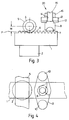
- the anti-roll pad 7 spans three of the rack teeth 6, and from Figure 4 that the pad extends substantially across the full width of the flat top of the rack teeth 6, bearing in mind that although the roots of the rack teeth extend the full width of the rack, the tops are curtailed, in conventional manner, because of the use of cylindrical stock for the rack.
- the reaction force to the torque T is now between the top of the teeth 6 and the pad 7, rather than the teeth flanks and the pinion 5.
- the pad 7 needs to contact a major part of one tooth 6, it need only contact a minor part of one or more adjacent teeth.
- FIG 5 shows part of a power-assisted vehicle steering mechanism comprising a housing 17 which is of cast construction and in which the rack 1 is mounted for sliding movement, the pinion 5 being shown only in outline.
- the right-hand end of the rack 1 is engaged by a ram 18 fitted with a piston ring 19 slidably mounted in a cylinder 21 fitted as a continuation to the housing 17. Hydraulic fluid is admitted to one side or other of the piston ring 19 in order to power assist movement of the rack 1, as appropriate.
- the support 2 for the rack is provided with a recess 22 at the end opposite to that on which the bearing surface 3 is formed, this recess receiving a spring 23 over which is fitted a retaining plate 24.
- the recess 22 is closed by a closure plate 25 bolted to the steering mechanism housing 17.
- the closure plate 25 is provided with a tapped hole 26 which receives an adjustment screw 27 provided with a lock nut 28, the adjustment screw being used to adjust the meshing relationship between the rack 1 and pinion 5 as discussed above.
- the anti-roll mechanism in accordance with the present invention which, as will be seen, is located immediately next to that part of the housing accommodating the pinion 5.
- the anti-roll mechanism 20 of this embodiment, of the invention comprises the same basic components as the anti-roll mechanism of Figures 1 and 2 but in this embodiment, the anti-roll pad 7 is provided with an extension 29 opposite the face in contact with the rack teeth 6, this extension being provided with a slot 31 and also receiving a collar 32 serving to retain a pin 33 within the slot 31.
- the pin 33 serves to prevent rotation of the anti-roll pad 7 about a vertical axis but allows movement about the longitudinal axis of the pad, as in the embodiment of Figures 3 and 4, to accommodate manufacturing tolerances.
- the key plate 12 and closure plate 13 of the embodiment of Figures 3 and 4 are dispensed with.
- the adjustment screw 15 is threadedly received directly in a collar 34 provided in the housing 17 and is locked into position using a locking compound, for example.
- the setting up and operation of the anti-roll mechanism is as described with reference to Figures 3 and 4 of the drawings.
- anti-roll mechanism 20 of Figures 3 and 4 can be used in place of the mechanism 20 of Figure 5.
- the support 2 and the anti-roll pad housing 8 are conveniently formed from a PTFE-loaded material, such as a synthetic plastics material, in order to provide a bearing surface for the rack with a very low co-efficient friction.
- Lubrication for the rack with respect both to the support 2 and the pad 7 is provided by grease, or other lubricant, provided within the housing 17 and being allowed to circulate around the components contained therein by virtue of the rack 1 being provided with a through bore.
- the present invention provides a relatively simple but highly effective anti-roll mechanism for the rack of a rack and pinion apparatus and thus represents a significant advance in the art.
Landscapes
- Engineering & Computer Science (AREA)
- Mechanical Engineering (AREA)
- Chemical & Material Sciences (AREA)
- Combustion & Propulsion (AREA)
- Transportation (AREA)
- General Engineering & Computer Science (AREA)
- Transmission Devices (AREA)
- Portable Nailing Machines And Staplers (AREA)
- Power Steering Mechanism (AREA)
- Gears, Cams (AREA)
Abstract
Description
- This invention relates to anti-roll mechanisms for rack and pinions and has been conceived in connection with a rack and pinion for a vehicle steering mechanism and will primarily be discussed in relation thereto. However, it is to be noted that the invention is applicable to rack and pinions used in other than vehicle steering mechanisms.
- A rack and pinion is a widely accepted mechanism for steering motor vehicles and it is recognised that to achieve positive steering, mesh clearance (backlash) between the teeth of the rack and pinion needs to be kept to a minimum. Ideally, zero backlash is required but manufacturing tolerances, however tight, make this virtually impossible without involving extra components and/or machining operations which introduce unacceptable higher manufacturing costs.
- It is common to employ a pinion with helical teeth and this gives rise to a force which imparts a rocking motion to the rack. Figure 1 of the accompany drawings illustrates a known rack and pinion for a steering mechanism in which the rack 1 is supported for axial sliding movement in a
support 2, the rack being formed from cylindrical stock and the support being provided with a corresponding part-cylindrical support surface 3. Theteeth 4 of thehelical pinion 5 mesh with theteeth 6 of the rack 1 and on rotation, the pinion generates an axial force FAX along its axis of rotation, which force acts at the pitch line P of the rack 1, the distance between the pitch line and the longitudinal axis of the rack 1 representing a moment arm M. The rotational force or torque T acting on the rack 1 is thus :-
rack teeth 6, giving rise to wear and/or damage. Clearly, this is undesirable especially when long term use is essential as in a vehicle steering mechanism. - Attempts have been made to minimise the rocking motion of the rack 1 due to the torque T, one arrangement being to provide inclined faces on the rack to give a general V-shaped cross-section to the rack as illustrated in Figure 2 of the accompanying drawings. The
support 3 for the rack 1 has a corresponding V-shaped mating surface formed therein. In view of the accuracy required, the inclined faces have to be machined and it will be appreciated that it is not a simple matter to effect this machining, relative to therack teeth 6, without tolerance or error and to produce likewise themating surface 3 on thesupport 2. Furthermore, additional errors are likely to be introduced when assembling the anti-roll mechanism in the housing of the steering mechanism. Consequently, not only is this anti-roll mechanism relatively expensive to manufacture, but the cumulative errors or tolerances contribute to a reduction in efficiency of operation of the rack and pinion, particularly the freedom of movement of the rack, which is unacceptable. - The primary object of the present invention is to provide an anti-roll mechanism for a rack and pinion which is relatively inexpensive to manufacture but which is effective without detracting from the efficiency of operation of the rack and pinion.
- According to the present invention, there is provided rack and pinion apparatus comprising a toothed rack, the tops of the teeth of which lie in a common plane, the rack and pinion apparatus further comprising an anti-roll mechanism having rack-teeth-engaging means mounted to permit relative movement between the rack and teeth-engaging means and so as to be in contact, at any given instant, with the tops of at least two teeth of the rack.
- Inasmuch as it is common practice to provide flat tops to the rack teeth and to ensure that these tops are co-planar, then the present invention makes use of this existing "surface" to provide the means for preventing rolling or rocking motion of the rack, thus dispensing with the relatively expensive machining or manufacturing equipment discussed above.
- The teeth-engaging means of the anti-roll mechanism may comprise a hardened pad, preferably supported in a carrier which is provided with means for adjusting the pad relative to the rack teeth in order to accommodate manufacturing tolerances. The pad may be part cylindrical with the carrier having a complementary part-cylindrical bearing surface to permit relative movement between the pad and carrier for alignment purposes.
- Instead of a pad, the teeth-engaging means may comprise one or more hardened rollers, each roller being arranged to be in engagement, at any given instant, with the tops of at least two rack teeth, the rack teeth necessarily being skewed with respect to the longitudinal axis of the rack for anti-roll rollers to be employed. If the amount of skew of the rack teeth is great enough, it is possible to employ a single roller because the latter will not be able to fall into the space between adjacent teeth which, if this were to happen, would negate the anti-roll function of the roller. When the skew of the rack teeth is not sufficient for a single roller to be employed, then two rollers may be used which are spaced apart such as to ensure that any given instant, at least one of the rollers is in contact with the flat tops of at least two teeth even if the other roller is located over the space between adjacent teeth. The or each roller may be mounted in a carrier which is mounted relative to the rack such that a roller cannot engage the space between two teeth.
- The anti-roll mechanism of the present invention may be employed in addition to, or instead of, the normal means employed to adjust the rack with respect to the pinion in order to set up the desired meshing relationship between the two.
- Rack and pinion apparatus embodying the present invention will now be described in greater detail, by way of example, with reference to the accompanying drawings, in which :-
- Figures 1 and 2 are diagrammatic illustrations of prior art rack and pinions,
- Figure 3 is a diagrammatic side view of one embodiment of the present invention,
- Figure 4 is a plan view of Figure 3, and
- Figure 5 is a cross-sectional view of a second embodiment of the present invention.
- Referring first to Figures 3 and 4, the first embodiment of the present invention by way of a rack and pinion apparatus comprises a rack 1, a
rack support 2 and apinion 5 with helically cutteeth 4, these components being similar to those described above with reference to Figure 1 of the drawings. It will be seen that theteeth 6 of the rack 1 are provided with flat tops which are co-planar. The rack 1 is formed from cylindrical stock and conveniently, the teeth are formed in series production with a single-pass broach which cuts the root flanks and tops directly into the rack bar, whereby the tops of theteeth 6 being in accurate alignment, i.e. co-planar. - In accordance with the present invention an
anti-roll mechanism 20 is provided comprising ananti-roll pad 7 of a hardened metal, such as steel, the pad having a part-cylindrical cross-section and being received in a pad-housing 8 which has a complementary part-cylindrical bearing surface 9, the pad being received therein in a manner which permits relative movement between these two components about the longitudinal axis of thepad 7 but not along that axis. Thehousing 8 is cylindrical but is provided with a pair of flats 11 at the end opposite to that in which the bearing surface 9 is formed and by which the housing is mounted, non-rotationally, in akey plate 12. Disposed over thekey plate 12 is aclosure plate 13 which is bolted, using theholes 10, to a housing of the steering mechanism of which the rack and pinion apparatus forms part but which is not shown in Figures 1 and 2 of the drawings. Theclosure plate 13 has a tappedhole 14 provided therein which receives anadjustment screw 15 by which the engagement of theanti-roll pad 7 with therack teeth 6 is set and then locked into position by alock nut 16. - When the rack and
pinion 1 and 5 are brought into basic meshing relationship, fine adjustment of this relationship is set by adjustment means associated with therack support 2, this adjustment means not being shown in Figures 1 and 2 but being illustrated in Figure 5 to which reference will be made hereafter. Following this adjustment, theanti-roll pad 7 is then adjusted into close contact withrack teeth 6, without overcoming the spring force of the adjustment means of thesupport 2, using theadjustment screw 15, the latter then being locked with thelock nut 16 in the selected position. In operation, thepinion 4 is rotated about a fixed axis and on rotation, moves the rack 1 to the left or the right, depending on the direction of rotation, this rack movement effecting steering movement of the vehicle and being augmented, in a power-assisted steering mechanism typically by hydraulic power. The rack 1 slides beneath theanti-roll pad 7, the latter serving to restrain the rack from any rocking movement about its longitudinal axis as a result of the torque imparted by the rotation of thepinion 4 as described above. It will be seen from Figure 3 that theanti-roll pad 7 spans three of therack teeth 6, and from Figure 4 that the pad extends substantially across the full width of the flat top of therack teeth 6, bearing in mind that although the roots of the rack teeth extend the full width of the rack, the tops are curtailed, in conventional manner, because of the use of cylindrical stock for the rack. It will be seen that the reaction force to the torque T is now between the top of theteeth 6 and thepad 7, rather than the teeth flanks and thepinion 5. Although thepad 7 needs to contact a major part of onetooth 6, it need only contact a minor part of one or more adjacent teeth. - Turning now to Figure 5, this shows part of a power-assisted vehicle steering mechanism comprising a
housing 17 which is of cast construction and in which the rack 1 is mounted for sliding movement, thepinion 5 being shown only in outline. The right-hand end of the rack 1 is engaged by aram 18 fitted with apiston ring 19 slidably mounted in acylinder 21 fitted as a continuation to thehousing 17. Hydraulic fluid is admitted to one side or other of thepiston ring 19 in order to power assist movement of the rack 1, as appropriate. - The
support 2 for the rack is provided with a recess 22 at the end opposite to that on which thebearing surface 3 is formed, this recess receiving aspring 23 over which is fitted aretaining plate 24. The recess 22 is closed by aclosure plate 25 bolted to the steering mechanism housing 17. Theclosure plate 25 is provided with a tapped hole 26 which receives an adjustment screw 27 provided with alock nut 28, the adjustment screw being used to adjust the meshing relationship between the rack 1 andpinion 5 as discussed above. On the side of thehousing 17 opposite to thesupport 2 there is provided the anti-roll mechanism in accordance with the present invention which, as will be seen, is located immediately next to that part of the housing accommodating thepinion 5. Theanti-roll mechanism 20 of this embodiment, of the invention comprises the same basic components as the anti-roll mechanism of Figures 1 and 2 but in this embodiment, theanti-roll pad 7 is provided with anextension 29 opposite the face in contact with therack teeth 6, this extension being provided with aslot 31 and also receiving acollar 32 serving to retain apin 33 within theslot 31. Thepin 33 serves to prevent rotation of theanti-roll pad 7 about a vertical axis but allows movement about the longitudinal axis of the pad, as in the embodiment of Figures 3 and 4, to accommodate manufacturing tolerances. Thus, in this embodiment, thekey plate 12 andclosure plate 13 of the embodiment of Figures 3 and 4 are dispensed with. Theadjustment screw 15 is threadedly received directly in acollar 34 provided in thehousing 17 and is locked into position using a locking compound, for example. The setting up and operation of the anti-roll mechanism is as described with reference to Figures 3 and 4 of the drawings. - It will be appreciated that the
anti-roll mechanism 20 of Figures 3 and 4 can be used in place of themechanism 20 of Figure 5. - The
support 2 and theanti-roll pad housing 8 are conveniently formed from a PTFE-loaded material, such as a synthetic plastics material, in order to provide a bearing surface for the rack with a very low co-efficient friction. Lubrication for the rack with respect both to thesupport 2 and thepad 7 is provided by grease, or other lubricant, provided within thehousing 17 and being allowed to circulate around the components contained therein by virtue of the rack 1 being provided with a through bore. - It will be seen that the present invention provides a relatively simple but highly effective anti-roll mechanism for the rack of a rack and pinion apparatus and thus represents a significant advance in the art.
Claims (13)
- Rack and pinion apparatus comprising a toothed rack (1), the tops of the teeth of which lie in a common plane, the rack and pinion apparatus further comprising an anti-roll mechanism (20) having rack-teeth-engaging means mounted to permit relative movement between the rack (1) and teeth-engaging means and so as to be in contact, at any given instant, with the tops of at least two teeth (6) of the rack.
- Apparatus according to claim 1, wherein the teeth-engaging means comprises a pad (7) supported in a carrier (8) provided with means for adjusting the pad relative to the rack teeth (6).
- Apparatus according to claim 2, wherein the pad (7) is mounted in the carrier (8) for relative movement with respect to the latter about at least one axis.
- Apparatus according to claim 2 or 3, wherein the pad (7) is part cylindrical.
- Apparatus according to any of claims 2 to 4, wherein the carrier (8) is mounted for non-rotational movement about an axis generally perpendicular to the longitudinal axis of the rack.
- Apparatus according to claim 5, wherein the carrier (8) is provided with a pair of flats (11) whereby it is non-rotationally mounted in a key plate (12) attached to a housing for the apparatus.
- Apparatus according to claim 5, wherein the pad (7) is provided with a slot or recess (31) on the side opposite to the face which is engageable with the rack teeth (6), the slot or recess (31) receiving an elongated member (33) retained in position by a collar (32), whereby the carrier is non-rotationally mounted.
- Apparatus according to claim 2, and any of claims 3 to 7 when appended thereto, wherein the adjustment means comprises a screw (15).
- Apparatus according to claim 1, wherein the teeth-engaging means comprise roller means.
- Apparatus according to claim 9, wherein the roller means comprise a single roller oriented generally transverse to the rack and in engagement with the tops of at least two rack teeth.
- Apparatus according to claim 9, wherein the roller means comprises a plurality of rollers spaced apart such that at any given instant at least one roller in engagement with the tops of at least two rack teeth.
- Apparatus according to any of the preceding claims and further comprising means (27) for adjustment the meshing relationship between the rack and pinion.
- A vehicle steering mechanism embodying rack and pinion apparatus according to any of the preceding claims.
Applications Claiming Priority (3)
| Application Number | Priority Date | Filing Date | Title |
|---|---|---|---|
| GB919105903A GB9105903D0 (en) | 1991-03-20 | 1991-03-20 | Anti-roll mechanism for a rack and pinion |
| GB9105903 | 1991-03-20 | ||
| PCT/GB1992/000493 WO1992016404A1 (en) | 1991-03-20 | 1992-03-19 | Anti-roll mechanism for a rack and pinion |
Publications (2)
| Publication Number | Publication Date |
|---|---|
| EP0575431A1 EP0575431A1 (en) | 1993-12-29 |
| EP0575431B1 true EP0575431B1 (en) | 1995-10-11 |
Family
ID=10691887
Family Applications (1)
| Application Number | Title | Priority Date | Filing Date |
|---|---|---|---|
| EP92906635A Expired - Lifetime EP0575431B1 (en) | 1991-03-20 | 1992-03-19 | Anti-roll mechanism for a rack and pinion |
Country Status (7)
| Country | Link |
|---|---|
| US (1) | US5429202A (en) |
| EP (1) | EP0575431B1 (en) |
| JP (1) | JPH06510588A (en) |
| DE (1) | DE69205419T2 (en) |
| ES (1) | ES2089508T3 (en) |
| GB (1) | GB9105903D0 (en) |
| WO (1) | WO1992016404A1 (en) |
Cited By (1)
| Publication number | Priority date | Publication date | Assignee | Title |
|---|---|---|---|---|
| DE102019208451A1 (en) * | 2019-06-11 | 2020-12-17 | Ford Global Technologies, Llc | Steering gear for a motor vehicle |
Families Citing this family (14)
| Publication number | Priority date | Publication date | Assignee | Title |
|---|---|---|---|---|
| DE4422556C1 (en) * | 1994-06-28 | 1995-10-05 | Daimler Benz Ag | Rack=and=pinion steering system for vehicle with servo motor |
| DE19647797A1 (en) * | 1996-11-19 | 1998-05-20 | Zahnradfabrik Friedrichshafen | Rack and pinion power steering |
| US6588995B2 (en) * | 1997-05-13 | 2003-07-08 | The Hillman Group, Inc. | Method and apparatus for aligning keys for cutting |
| DE19726697A1 (en) * | 1997-06-24 | 1999-01-07 | Zahnradfabrik Friedrichshafen | Method of manufacturing a rack |
| US6115109A (en) * | 1998-06-04 | 2000-09-05 | Fujifilm Electronics Imaging Ltd. | Apparatus and method for scanning a light beam over an image surface |
| WO2001015956A2 (en) * | 1999-09-01 | 2001-03-08 | Delphi Technologies, Inc. | Electric power assisted rack and pinion system |
| US6749040B1 (en) * | 1999-09-01 | 2004-06-15 | Delphi Technologies, Inc. | Electric power assisted rack and pinion system |
| US20030198795A1 (en) * | 2002-04-17 | 2003-10-23 | Grant William K. | Modular material design system and method |
| US9101990B2 (en) | 2006-01-23 | 2015-08-11 | Hy-Ko Products | Key duplication machine |
| EP1976656B1 (en) | 2006-01-23 | 2014-10-29 | Hy-Ko Products Company | Key duplication machine |
| MX343763B (en) | 2009-05-01 | 2016-11-18 | Hy-Ko Products | Key blank identification system with groove scanning. |
| US8634655B2 (en) | 2009-05-01 | 2014-01-21 | Hy-Ko Products Company | Key blank identification system with bitting analysis |
| JP5273228B2 (en) * | 2011-01-21 | 2013-08-28 | 日本精工株式会社 | Rack and pinion steering system |
| US9818041B2 (en) | 2015-08-03 | 2017-11-14 | Hy-Ko Products Company | High security key scanning system |
Family Cites Families (7)
| Publication number | Priority date | Publication date | Assignee | Title |
|---|---|---|---|---|
| US2193898A (en) * | 1935-12-09 | 1940-03-19 | Vaco Products Inc | Steering mechanism |
| US3157061A (en) * | 1962-03-22 | 1964-11-17 | Eng Productions Clevedon Ltd | Steering gear |
| US3897845A (en) * | 1973-04-10 | 1975-08-05 | Bosch Gmbh Robert | Power steering system |
| US4584893A (en) * | 1982-03-17 | 1986-04-29 | Harcross Engineering (Barnstaple) Ltd. | Lubrication of rack and pinion apparatus |
| US4599911A (en) * | 1984-09-12 | 1986-07-15 | Bendiberica S.A. | Compact assisted steering mechanism for an automotive vehicle |
| DE8712285U1 (en) * | 1986-10-08 | 1987-10-29 | Pfaff-Silberblau Hebezeugfabrik GmbH, 86316 Friedberg | Linear drive unit with rack drive |
| GB8811966D0 (en) * | 1988-05-20 | 1988-06-22 | Lucas Ind Plc | Power assistance for vehicle steering mechanisms |
-
1991
- 1991-03-20 GB GB919105903A patent/GB9105903D0/en active Pending
-
1992
- 1992-03-19 JP JP4506398A patent/JPH06510588A/en active Pending
- 1992-03-19 EP EP92906635A patent/EP0575431B1/en not_active Expired - Lifetime
- 1992-03-19 DE DE69205419T patent/DE69205419T2/en not_active Expired - Fee Related
- 1992-03-19 ES ES92906635T patent/ES2089508T3/en not_active Expired - Lifetime
- 1992-03-19 WO PCT/GB1992/000493 patent/WO1992016404A1/en not_active Ceased
- 1992-03-19 US US08/117,167 patent/US5429202A/en not_active Expired - Fee Related
Cited By (1)
| Publication number | Priority date | Publication date | Assignee | Title |
|---|---|---|---|---|
| DE102019208451A1 (en) * | 2019-06-11 | 2020-12-17 | Ford Global Technologies, Llc | Steering gear for a motor vehicle |
Also Published As
| Publication number | Publication date |
|---|---|
| ES2089508T3 (en) | 1996-10-01 |
| DE69205419D1 (en) | 1995-11-16 |
| DE69205419T2 (en) | 1996-04-04 |
| US5429202A (en) | 1995-07-04 |
| GB9105903D0 (en) | 1991-05-08 |
| JPH06510588A (en) | 1994-11-24 |
| WO1992016404A1 (en) | 1992-10-01 |
| EP0575431A1 (en) | 1993-12-29 |
Similar Documents
| Publication | Publication Date | Title |
|---|---|---|
| US5429202A (en) | Anti-roll mechanism for a rack and pinion | |
| US4747321A (en) | Anti-backlash gear assembly | |
| DE69504540T2 (en) | Electric power steering | |
| EP2776220B1 (en) | Vehicle steering system transmission | |
| US4116085A (en) | Rack and pinion steering gear | |
| EP1402201B1 (en) | Actuator for a vehicle steering device | |
| US4531603A (en) | Rack and pinion steering gear with adjustable low friction anti-roll rack bearing | |
| DE1480680A1 (en) | Steering gears, especially for motor vehicles | |
| DE2735958B2 (en) | Steering gears for automobiles | |
| US7520366B2 (en) | Method for producing electric power steering apparatus | |
| DE3332483A1 (en) | Rack steering | |
| EP0146547A1 (en) | Steering mechanism. | |
| DE3027212C2 (en) | Hydraulic booster unit for auxiliary power support, in particular of motor vehicle steering systems | |
| DE2742427A1 (en) | RACK STEERING, ESPECIALLY FOR MOTOR VEHICLES | |
| EP1048824A2 (en) | Combustion engine with frontal gear drive | |
| DE3803427A1 (en) | Gear mechanism | |
| DE19631758A1 (en) | Vehicle drive unit structure | |
| US3505899A (en) | Variable ratio steering gear | |
| GB2169567A (en) | Power assisted steering gear assembly | |
| EP3760571B1 (en) | Chain drive system | |
| AU675034B2 (en) | Steering gear apparatus of rack-and-pinion type | |
| DE19832382A1 (en) | Coupling gear for a variable valve control of internal combustion engines | |
| EP1702830B1 (en) | Electric power steering device | |
| DE937809C (en) | Limitation of the steering angle in vehicle steering systems | |
| DE4220127C1 (en) |
Legal Events
| Date | Code | Title | Description |
|---|---|---|---|
| PUAI | Public reference made under article 153(3) epc to a published international application that has entered the european phase |
Free format text: ORIGINAL CODE: 0009012 |
|
| 17P | Request for examination filed |
Effective date: 19930917 |
|
| AK | Designated contracting states |
Kind code of ref document: A1 Designated state(s): DE ES FR GB IT |
|
| 17Q | First examination report despatched |
Effective date: 19941213 |
|
| GRAA | (expected) grant |
Free format text: ORIGINAL CODE: 0009210 |
|
| AK | Designated contracting states |
Kind code of ref document: B1 Designated state(s): DE ES FR GB IT |
|
| ITF | It: translation for a ep patent filed | ||
| REF | Corresponds to: |
Ref document number: 69205419 Country of ref document: DE Date of ref document: 19951116 |
|
| REG | Reference to a national code |
Ref country code: ES Ref legal event code: BA2A Ref document number: 2089508 Country of ref document: ES Kind code of ref document: T3 |
|
| ET | Fr: translation filed | ||
| PLBE | No opposition filed within time limit |
Free format text: ORIGINAL CODE: 0009261 |
|
| REG | Reference to a national code |
Ref country code: ES Ref legal event code: FG2A Ref document number: 2089508 Country of ref document: ES Kind code of ref document: T3 |
|
| 26N | No opposition filed | ||
| REG | Reference to a national code |
Ref country code: ES Ref legal event code: FG2A Ref document number: 2089508 Country of ref document: ES Kind code of ref document: T3 |
|
| PGFP | Annual fee paid to national office [announced via postgrant information from national office to epo] |
Ref country code: GB Payment date: 19980310 Year of fee payment: 7 Ref country code: FR Payment date: 19980310 Year of fee payment: 7 |
|
| PGFP | Annual fee paid to national office [announced via postgrant information from national office to epo] |
Ref country code: ES Payment date: 19980327 Year of fee payment: 7 Ref country code: DE Payment date: 19980327 Year of fee payment: 7 |
|
| PG25 | Lapsed in a contracting state [announced via postgrant information from national office to epo] |
Ref country code: GB Free format text: LAPSE BECAUSE OF NON-PAYMENT OF DUE FEES Effective date: 19990319 |
|
| PG25 | Lapsed in a contracting state [announced via postgrant information from national office to epo] |
Ref country code: ES Free format text: LAPSE BECAUSE OF NON-PAYMENT OF DUE FEES Effective date: 19990320 |
|
| GBPC | Gb: european patent ceased through non-payment of renewal fee |
Effective date: 19990319 |
|
| PG25 | Lapsed in a contracting state [announced via postgrant information from national office to epo] |
Ref country code: FR Free format text: LAPSE BECAUSE OF NON-PAYMENT OF DUE FEES Effective date: 19991130 |
|
| REG | Reference to a national code |
Ref country code: FR Ref legal event code: ST |
|
| PG25 | Lapsed in a contracting state [announced via postgrant information from national office to epo] |
Ref country code: DE Free format text: LAPSE BECAUSE OF NON-PAYMENT OF DUE FEES Effective date: 20000101 |
|
| REG | Reference to a national code |
Ref country code: ES Ref legal event code: FD2A Effective date: 20010503 |
|
| PG25 | Lapsed in a contracting state [announced via postgrant information from national office to epo] |
Ref country code: IT Free format text: LAPSE BECAUSE OF NON-PAYMENT OF DUE FEES Effective date: 20050319 |