EP0575136B1 - Coin dispenser and coin pay-out method - Google Patents
Coin dispenser and coin pay-out method Download PDFInfo
- Publication number
- EP0575136B1 EP0575136B1 EP93304627A EP93304627A EP0575136B1 EP 0575136 B1 EP0575136 B1 EP 0575136B1 EP 93304627 A EP93304627 A EP 93304627A EP 93304627 A EP93304627 A EP 93304627A EP 0575136 B1 EP0575136 B1 EP 0575136B1
- Authority
- EP
- European Patent Office
- Prior art keywords
- coin
- pay
- detecting signal
- discharging
- dispenser
- Prior art date
- Legal status (The legal status is an assumption and is not a legal conclusion. Google has not performed a legal analysis and makes no representation as to the accuracy of the status listed.)
- Expired - Lifetime
Links
Images



Classifications
-
- G—PHYSICS
- G07—CHECKING-DEVICES
- G07D—HANDLING OF COINS OR VALUABLE PAPERS, e.g. TESTING, SORTING BY DENOMINATIONS, COUNTING, DISPENSING, CHANGING OR DEPOSITING
- G07D1/00—Coin dispensers
- G07D1/02—Coin dispensers giving change
-
- G—PHYSICS
- G07—CHECKING-DEVICES
- G07F—COIN-FREED OR LIKE APPARATUS
- G07F17/00—Coin-freed apparatus for hiring articles; Coin-freed facilities or services
- G07F17/32—Coin-freed apparatus for hiring articles; Coin-freed facilities or services for games, toys, sports, or amusements
Definitions
- the present invention relates to a coin dispenser and a method of paying out coins. More particularly, the present invention relates to a coin dispenser applied to a coin-operated machine such as a gaming machine, and relates also to a coin pay-out method in which fraud can be detected in operation of the coin-operated machine.
- a coin-operated machine is operated in response to insertion of coins, tokens, medals or other disks (herein referred to as coins) into an inlet slot.
- Such coin-operated machines include slot machines, other gaming machines, vending machines and money-changing machines.
- a slot machine for example, incorporates a coin dispenser, which discharges coins, as stored in the slot machine, down into a coin trough.
- a coin pay-out sensor At a discharging port of the coin dispenser, there is arranged a coin pay-out sensor, which is adapted to detecting a coin as passed through the discharging port, so as to send a detecting signal to a pay-out counter.
- the counter counts detecting signals, and when the counted value comes up to be equal to the number of coins according to dividend as instructed to the coin dispenser, a motor for discharge is stopped from rotating, to terminate discharge of coins.
- the conventional coin dispenser is vulnerable to fraud committed by a fraudulent player to the pay-out sensor.
- a flexible long tool is inserted into the pay-out sensor through the trough in advance of instruction for pay-out.
- the sensor is kept insensitive coin by coin, keeping the pay-out counter from stepping.
- the pay-out counter counts no steps or steps fewer than coins to be paid out, the player could receive coins including extra coins not detected at the pay-out sensor, thus more coins than is proper.
- EP-A-0 266 021 discloses a coin dispenser including a rotary disc.
- a logic control circuit is provided for controlling the dispensation of coins.
- the logic circuit is arranged to rotate the disc in reverse in the event that it detects a jam.
- EP-A-0 312 316 discloses a coin dispenser including an alarm unit. If an output signal sent from a count sensor to the alarm unit after the output signal from a preset counter is inputted to the alarm unit, cheating is detected and an alarm is triggered.
- DE-A-3 128 235 discloses a coin dispenser whose output path is provided with hinged flaps.
- a coin dispenser for paying out a coin through a discharging port when receiving instruction of pay-out, comprising:
- a discharging section discharges the coin toward the discharging port.
- a sensor is arranged at the discharging port for generating a detecting signal when detecting the coin.
- Counting means counts the detecting signal so as to generate a count signal.
- Control means drives the discharging section in accordance with the pay-out instruction, and stops the discharging section from actuation to complete the pay-out when a count value of the count signal comes to be a predetermined number of coins to be paid out.
- the control means monitors the sensor and, if the detecting signal is received before receiving the pay-out instruction, keeps the discharging section from actuation. Therefore, a coin-operated machine can be protected from fraud with the provision of a simple structure.
- a blocking plate is arranged to be shiftable between respective positions of closing and opening the discharging port, and to be pushed by the coin as passed through the discharging port, thereby displaced from the closed position into the open position so as to allow the coin to pass.
- a known coin dispenser has a jam-eliminating construction in which, if it detects an unchanged level in the detecting signal over a predetermined period, the disk is rotated reverse at an amount and subsequently rotated normally. This is for the purpose of eliminating a jamming of coins in the coin dispenser the coin is discharge and would lack further detecting signals at the pay-out sensor. Such jam being eliminated, the motor for discharge is prevented from being loaded excessively, and protected from damage.
- the coin dispenser with the jam-eliminating construction would be still vulnerable to fraud committed by a fraudulent player to the pay-out sensor with a long tool. In such a fraud, the tool would be at first inserted into the pay-out sensor in advance of receiving instruction for pay-out.
- the sensor would be kept insensitive coin by coin, keeping the pay-out counter from stepping. Then the external tool would be withdrawn during the reverse rotation of the motor, before the motor would again rotate normally. As illustrated in Fig. 7, four coins are discharged while counting only one in the first normal rotation, as well as five coins are discharged while counting five in the second normal rotation. Thus the player would fraudulently obtain the nine coins during the six steps as counted by use of the external tool.
- the novel coin dispenser in combination with a jam-eliminating construction can protect a coin-operated machine from fraud with the provision of a simple structure.
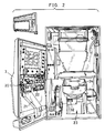
- a front door 3 is openably mounted on a main body 2 of the slot machine.
- windows 4 for external observation of symbols on reels incorporated in respective reel units 5, 6 and 7.
- an inlet slot 8 Under the windows 4, there are arranged an inlet slot 8 through which coins C are inserted, a starting lever 10 for rotating the reel units 5 to 7 at a time, and stop buttons 11 and 13 for stopping the reel units 5 to 7 respectively.
- a player inserts one, two or three coins C into the inlet slot 8. Winning lines for effective alignment of symbols are selected among horizontal or slant lines across the three reel units 5 to 7. The more coins C are inserted, the more winning lines are selected. Operation of the starting lever 10 rotating the reel units 5 to 7, the stop buttons 11 to 13 are actuated to stop the reel units 5 to 7 respectively. Upon stopping in the positions meeting a winning combination as shown and upon determination of a win, coins C are paid out to a trough 14. An indicator 15 displays also the number of coins C as paid out.
- the inside of the front door 3 is provided with a coin selector 20 having an inspector sensor 20a for judging acceptability of the coin C as inserted, and a gate plate 20b.
- the gate plate 20b opens a return chute 21 to pass the coin C down to the trough 14.
- the gate plate 20b opens an accepting chute 22 to pass the coin C down to a storage bucket 24 of the novel coin dispenser 23 in the center of the slot machine.
- a coin acceptance sensor 35 which is connected to an acceptance counter 36 for counting only the acceptable coins as inserted, later to be described in detail.
- the reel units 5 to 7, including each reel, stepping motor, and sensor for monitoring a rotational position of the reel are omitted from Fig. 2, but are actually mounted in the slot machine.
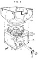
- Fig. 3 illustrates the coin dispenser 23, which is generally constituted of a electrically driven discharging section 25 and the storage bucket 24.
- the discharging section 25 has a motor 49 actuated by a pay-out controller 45 and a rotary disk 27 rotated by the motor 49.
- the disk 27 is rotated counterclockwise, the coins brought through a passage opening 24a in the storage bucket 24 are subjected to centrifugal force on the disk 27, are moved into an exit slot and guided through a communicating guide passageway 28 formed in a discharging section 25.
- a coin pay-out sensor 29 of a photoelectric type constituted of a light projector 29a and a light receiver 29b.
- the receiver 29b When a beam from the projector 29a is blocked by a coin C, the receiver 29b generates a detecting signal of the High level, and sends it to the pay-out controller 45 and a pay-out counter 47, later to be described.
- a coverage 30 is fixed at the passageway 28 to cover the pay-out sensor 29 by use of screws.
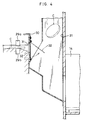
- the coverage 30 is provided with a discharging slot 31 as port and a hinged plate 32 openably blocking the slot 31.
- the weight of the blocking plate 32 causes it to close the slot 31, as indicated by the full line, so as to prevent players from inserting a long tool through the trough 14 into the slot 31, e.g. prevent fraudulent players from committing fraud of operating the pay-out sensor 29 externally.
- the coin C presses the blocking plate 32 to the outside and swings it into the position as indicated with the phantom line so as to open the slot 31 entirely.
- the coin C as passed through the slot 31 is dropped into the return chute 21 and discharged into the trough 14.
- the coin acceptance sensor 35 detects acceptable coins C as inserted into the inlet slot 8.
- the acceptable coins C as detected is counted by the acceptance counter 36 so as to determine the number of winning lines of symbols.
- the acceptance sensor 35 in view of at least one accepted coin C, generates a start-enabling signal and sends it to a starter 37, which, in response to actuation of the starting lever 10, generates a starting signal.
- the starting signal is sent into a reel controller 38 and a random number generator 39.
- the reel controller 38 drives stepping motors respectively incorporated in the reel units 5 to 7.
- the random number generator 39 in response to the starting signal, samples one random number from a train of random numbers within a predetermined range, and enters the sampled number into a prize judging circuit 40.
- the prize judging circuit 40 determines a win of the game as played.
- a win grade table 41 which stores information of all the retrievable random numbers respectively as associated with either of a great win, a medium win, a small win and a loss (no win).
- the prize judging circuit 40 refers to the win grade table 41, and determines one of the four winning grades associated with the sampled number.
- a stop-designating table stored in the prize judging circuit 40 is referred to, so that, according to the one winning grade as address data, a combination of stop-designated positions is sent into the reel controller 38.
- a stop signal generator 42 sends a stop signal to the reel controller 38, to start a control of stopping the reel units 5 to 7.
- the symbols appear along a respective effective winning line in such a manner as to meet a particular symbol combination associated with the winning grade as selected in the prize judging circuit 40.
- the reel units 5 to 7 send back information of stopped rotational positions to the reel controller 38, the prize judging circuit 40 receives the stopped rotational position information from the reel controller 38 and confirms the stopped positions as associated with the one winning grade. To confirm this, a winning combination table stored in the prize judging circuit 40 is referred to, so that, according to combination of stopped positions as address data, a winning combination is obtained.
- the prize judging circuit 40 refers to a dividend determining table 46 storing association of each winning grade with dividend, and then sends to a pay-out controller 45 a loss signal or a pay-out signal representing the number of coins to be paid and constituting instruction of pay-out.
- the pay-out controller 45 When a loss or pay-out signal is generated, the pay-out controller 45 initially monitors the pay-out sensor 29 to find existence of a detecting signal. If the pay-out sensor 29 has generated a detecting signal, then the pay-out controller 45 drives the coin selector 20, to open the return chute 21, to communicate the inlet slot 8 directly to the trough 14, and to avoid paying of coins C. The controller 45 also drives the indicator 15 to display an error. If the pay-out sensor 29 has not generated any detecting signal despite existence of a pay-out signal, then the pay-out controller 45 sends a drive signal to a driver 48. If a loss signal is received without generation of any detecting signal from the pay-out sensor 29, a game is terminated without paying out of any coins C.
- the motor 49 When a drive signal is sent in the driver 48, the motor 49 is rotated normally namely in the forward direction, to rotate the disk 27. The rotation of the disk 27 sends the coins C from under the storage bucket 24, through the passageway 28 toward the discharging slot 31.
- a detecting signal is sent into the pay-out counter 47 and the pay-out controller 45.
- the pay-out counter 47 incrementally counts one step upon lowering of the detecting signal. When the counted value comes up to be equal to the number of coins according to dividend as associated, the pay-out controller 45 stops the motor 49 from rotating.
- this jam-eliminating sequence can be performed when no detecting signal is generated for three seconds even after starting the motor 49, when no detecting signal is generated after the latest detecting signal, and when one detecting signal has a temporal width at the High level over four seconds.
- the starting lever 10 With the coin C inserted through the inlet slot 8, the starting lever 10 is swung down, to operate rotation of the reel units 5 to 7.
- the stop buttons 11 to 13 are pressed to stop the reel units 5 to 7.
- the prize judging circuit 40 sends a pay-out signal to the pay-out controller 45.
- the pay-out controller 45 When the pay-out signal is sent to the pay-out controller 45, the pay-out controller 45 detects existence of a detecting signal. If there has been a detecting signal generated, then the pay-out controller 45 drives the coin selector 20, opens the return chute 21, communicates the inlet slot 8 directly to the trough 14, and avoids paying of coins C.
- the indicator 15 is caused to display an error.
- the novel construction avoids such a fraud that insertion of a flexible long tool through the trough 14 would keep the pay-out sensor 29 from detecting coins and cause the coin dispenser 23 to pay more coins than is enough.
- the error as detected is indicated on the indicator 15, it can be signaled both visually and acoustically, e.g. by use of a loud speaker or a buzzer.
- the pay-out controller 45 When no detecting signal has been generated by the pay-out sensor 29, the pay-out controller 45 receives a pay-out signal associated with a dividend, to cause the driver 48 to rotate the motor 49 normally.
- the coin C is guided through the passageway 28 into the slot 31, pushes open the blocking plate 32, and falls through the return chute 21 down to the trough 14.
- the blocking plate 32 hinders external tools from insertion, it can prevent a fraud of causing the pay-out sensor 29 to malfunction, and causing the coin dispenser 23 to pay more coins than is enough.
- the pay-out controller 45 stops the motor 49 from rotating. Pay-out is completed, to terminate one game.
- the pay-out controller 45 detects a detecting signal unchanged between the High and Low levels for several seconds in normal rotation of the motor 49, it is estimated there to be jamming of coins.
- the motor 49 is stopped, and then rotated reverse for a predetermined period. This is effective for eliminating such a jamming of coins that the coins are overlapped one on another in a manner of giving rise to a gap or hollowness between or under the coins.
- the motor 49 is rotated in the normal direction again.
- the coins are discharged through the discharging slot 31.
- the pay-out controller 45 again receives lowering of the detecting signals within the predetermined period.
- the pay-out counter 47 counts the coins as paid out, until the controller 45 judges that the count value has come up to the dividend as retrieved.
- the controller 45 completes pay-out by stopping the motor 49.
- the pay-out controller 45 detects a detecting signal unchanged between the High and Low levels for several seconds for the second time. If it does, then the motor 49 in the coin dispenser 23 is stopped.
- the pay-out controller 45 drives the coin selector 20, opens the return chute 21, communicates the inlet slot 8 directly to the trough 14, and avoids playing of coins C.
- the indicator 15 is caused to display an error.
- a loss signal is generated to terminate the game. If a detecting signal is generated before generation of a loss signal, the controller 45 drives the coin selector 20 to communicate the inlet slot 8 to the trough 14 for avoidance of coin acceptance. The indicator displays an error, upon which the error is acoustically signaled as well.
- the pay-out counter 47 is of a general type of counting step by step.
- a preset counter may be used instead, which may store a predetermined number, e.g. ten of coins, and may be adapted to generate a signal of termination of counting the predetermined number.
- a signal of the predetermined number may be sent to the preset counter from the pay-out controller 45 according to a pay-out signal associated with one particular dividend to be paid according to the combination of stopped positions.
- existence of a detecting signal is monitored after generation of a pay-out or loss signal.
- existence of a detecting signal may be monitored after stopping of the reels before generation of a pay-out or loss signal.
- Existence of a detecting signal also, may be monitored periodically.
Landscapes
- Physics & Mathematics (AREA)
- General Physics & Mathematics (AREA)
- Slot Machines And Peripheral Devices (AREA)
- Pinball Game Machines (AREA)
- Detergent Compositions (AREA)
- Control Of Vending Devices And Auxiliary Devices For Vending Devices (AREA)
Abstract
Description
Claims (15)
- A coin dispenser (23) for paying out a coin (C) through a discharging port (31) when receiving instruction of pay-out, comprising:a discharging section (25) for discharging said coin toward said discharging port;a sensor (29) arranged at said discharging port for generating a detecting signal when detecting said coin;counting means (47) for counting said detecting signal so as to generate a count signal; andcontrol means (45) for driving said discharging section in accordance with said pay-out instruction, and for stopping said discharging section from actuation to complete said pay-out when a count value of said count signal comes to be a predetermined number of coins to be paid out, characterised in that said control means (45) is arranged to keep said discharging section (25) from actuation if said detecting signal is received before said pay-out instruction.
- A coin dispenser as defined in claim 1, wherein existence of said detecting signal is checked when receiving said pay-out instruction.
- A coin dispenser as defined in claim 1 or 2, wherein, if said detecting signal is received before receiving said pay-out instruction or after completing said pay-out, said control means (45) further signals an error.
- A coin dispenser as defined in claim 3, wherein said error is adapted to announcement of fraudulent external operation committed to said sensor (29).
- A coin dispenser as defined in claim 4, further comprising an external indicator (15) for signaling said error visually.
- A coin dispenser as defined in claim 1, 2, 3 or 4, which is incorporated in a coin-operated machine (2);which further comprises a storage section (24) arranged upstream from said discharging section (25) for storing a plurality of coins (C), anda selector (20) for exiting said coin, as inserted into said coin-operated machine, as soon as said control means has signaled said error.
- A coin dispenser as defined in claim 6, wherein said selector (20) further inspects said coin (C) as inserted into said coin-operated machine (2) in order to guide said coin into said storage section (24) when said coin is acceptable, and to exit said coin when said coin is unacceptable.
- A coin dispenser as defined in claim 7, wherein:a passage opening (24a) is formed in a bottom of said storage section (24);said discharging section (25) includes:a disk (27) for receiving a coin supplied from said storage section through said passage opening, and for rotating said coin thereon to slide said coin outward under centrifugal force; anda guide passageway (28) open to a circumference of said disk for guiding said coin, as slid under centrifugal force, toward said discharging port.
- A coin dispenser as defined in claim 8, wherein, if said control means (45) detects an unchanged level in said detecting signal over a predetermined period, said disk (27) is rotated reverse at an amount and subsequently rotated normally.
- A coin dispenser as defined in claim 9, wherein, if said control means (45) detects an unchanged level in said detecting signal over a predetermined period after said reverse and normal rotation of said disk (27), said control means signals an error.
- A coin dispenser as defined in any one of the preceding claims, further comprising a blocking plate (32) arranged to be shiftable between respective positions of closing and opening said discharging port (31), and to be pushed by said coin as passed through said discharging port, thereby displaced from said closed position into said open position so as to allow said coin to pass.
- A coin dispenser as defined in claim 11, wherein said blocking plate (32) is arranged outside said discharging port (31), and is externally inoperable from said closed position toward said open position.
- A coin dispenser as defined in claim 12, wherein said blocking plate (32) is hinged rotatably, and is in said closed position under gravity.
- A method of paying a coin (C) out of a coin dispenser (23) in which said coin is discharged through a discharging port (31) by driving a discharging section (25) when receiving instruction of pay-out, comprising:generating a detecting signal when detecting said coin at said discharging port;counting said detecting signal;stopping said discharging section from actuation to complete said pay-out when detecting signals as counted come to be a predetermined number of coins to be paid out; andif said detecting signal is received before said pay-out instruction, keeping said discharging section from actuation.
- A coin pay-out method as defined in claim 14, further comprising steps of:if said detecting signal is received before receiving said pay-out instruction, signaling an error; andif said detecting signal is received after completing said pay-out, signaling an error.
Applications Claiming Priority (2)
| Application Number | Priority Date | Filing Date | Title |
|---|---|---|---|
| JP161211/92 | 1992-06-19 | ||
| JP4161211A JP2781495B2 (en) | 1992-06-19 | 1992-06-19 | Coin payout device |
Publications (2)
| Publication Number | Publication Date |
|---|---|
| EP0575136A1 EP0575136A1 (en) | 1993-12-22 |
| EP0575136B1 true EP0575136B1 (en) | 1998-08-26 |
Family
ID=15730722
Family Applications (1)
| Application Number | Title | Priority Date | Filing Date |
|---|---|---|---|
| EP93304627A Expired - Lifetime EP0575136B1 (en) | 1992-06-19 | 1993-06-15 | Coin dispenser and coin pay-out method |
Country Status (7)
| Country | Link |
|---|---|
| US (1) | US5441447A (en) |
| EP (1) | EP0575136B1 (en) |
| JP (1) | JP2781495B2 (en) |
| CN (1) | CN1035407C (en) |
| AT (1) | ATE170311T1 (en) |
| AU (1) | AU659739B2 (en) |
| DE (1) | DE69320551T2 (en) |
Cited By (3)
| Publication number | Priority date | Publication date | Assignee | Title |
|---|---|---|---|---|
| GB2296359A (en) * | 1994-12-20 | 1996-06-26 | Jpm Int Ltd | Coin handling apparatus |
| GB2332552A (en) * | 1997-12-18 | 1999-06-23 | Mars Inc | Coin mechanism for vending machine |
| US6047966A (en) * | 1997-10-14 | 2000-04-11 | Universal Sales Co., Ltd. | Game machine having groove for arranging coins |
Families Citing this family (13)
| Publication number | Priority date | Publication date | Assignee | Title |
|---|---|---|---|---|
| GB9912665D0 (en) * | 1999-05-28 | 1999-07-28 | Igt Uk Limited | Entertainment machines |
| US6749052B2 (en) * | 2000-10-19 | 2004-06-15 | Igames Entertainment, Inc. | Anti-cheating device for a gaming machine |
| JP2004166822A (en) * | 2002-11-18 | 2004-06-17 | Aruze Corp | Gaming machine |
| JP4623491B2 (en) * | 2004-06-30 | 2011-02-02 | サミー株式会社 | Revolving machine |
| JP5066679B2 (en) * | 2006-06-12 | 2012-11-07 | 旭精工株式会社 | Disk sorting device |
| JP5044838B2 (en) * | 2006-07-12 | 2012-10-10 | 旭精工株式会社 | Coin selector |
| JP5016877B2 (en) * | 2006-09-08 | 2012-09-05 | マミヤ・オーピー株式会社 | Coin-shaped member feeding device |
| JP5066674B2 (en) * | 2006-11-01 | 2012-11-07 | 旭精工株式会社 | Coin selector |
| JP2008276616A (en) * | 2007-05-01 | 2008-11-13 | Asahi Seiko Kk | False detection prevention device in coin hopper |
| CN106204897A (en) * | 2016-07-26 | 2016-12-07 | 南京中钞长城金融设备有限公司 | A kind of coin anti-sticking conveyer device |
| CN106652175A (en) * | 2016-09-26 | 2017-05-10 | 深圳怡化电脑股份有限公司 | Method and apparatus for controlling banknote recognition units to collect information |
| WO2024095590A1 (en) * | 2022-11-04 | 2024-05-10 | 日本金銭機械株式会社 | Coin-processing device |
| JP7671386B1 (en) * | 2024-03-15 | 2025-05-01 | 日本金銭機械株式会社 | Coin Processing Device |
Family Cites Families (10)
| Publication number | Priority date | Publication date | Assignee | Title |
|---|---|---|---|---|
| JPS5713593A (en) * | 1980-06-27 | 1982-01-23 | Laurel Bank Machine Co | Counting circuit for coin counter |
| JPS57128884U (en) * | 1981-02-03 | 1982-08-11 | ||
| DE3128235A1 (en) * | 1981-07-14 | 1983-02-03 | Licentia Patent-Verwaltungs-Gmbh, 6000 Frankfurt | SAFETY DEVICE |
| GB2124006B (en) * | 1982-07-20 | 1986-02-05 | Jpm | Improvements relating to coin dispensers |
| JPS59186580A (en) * | 1983-04-08 | 1984-10-23 | 株式会社ユニバ−サル | Throttle machine |
| EP0209357B1 (en) * | 1985-07-17 | 1992-10-14 | Kabushiki Kaisha Universal | Coin pay-out apparatus |
| GB8625531D0 (en) * | 1986-10-24 | 1986-11-26 | Coin Controls | Coin dispensing apparatus |
| US4923430A (en) * | 1987-10-14 | 1990-05-08 | Kabushiki Kaisha Sigma | Coin payout apparatus in gaming device |
| US5146492A (en) * | 1991-07-18 | 1992-09-08 | Steve Stone | Anti-explosive return coin discharge unit for the cabinet of a coin operable telephone |
| JP3000779U (en) * | 1994-02-04 | 1994-08-16 | 新湾測器股▲ふん▼有限公司 | Reverse Osmosis Pure Water System Liquid Temperature Conductivity Combined Measuring Tube Device |
-
1992
- 1992-06-19 JP JP4161211A patent/JP2781495B2/en not_active Expired - Lifetime
-
1993
- 1993-06-04 AU AU40064/93A patent/AU659739B2/en not_active Expired
- 1993-06-15 DE DE69320551T patent/DE69320551T2/en not_active Expired - Lifetime
- 1993-06-15 EP EP93304627A patent/EP0575136B1/en not_active Expired - Lifetime
- 1993-06-15 AT AT93304627T patent/ATE170311T1/en active
- 1993-06-19 CN CN93107237A patent/CN1035407C/en not_active Expired - Lifetime
- 1993-06-21 US US08/079,520 patent/US5441447A/en not_active Expired - Lifetime
Cited By (4)
| Publication number | Priority date | Publication date | Assignee | Title |
|---|---|---|---|---|
| GB2296359A (en) * | 1994-12-20 | 1996-06-26 | Jpm Int Ltd | Coin handling apparatus |
| US6047966A (en) * | 1997-10-14 | 2000-04-11 | Universal Sales Co., Ltd. | Game machine having groove for arranging coins |
| US6464221B1 (en) | 1997-10-14 | 2002-10-15 | Universal Sales Co., Ltd. | Coin receiving pan of a game machine having a tray with grooves for arranging coins |
| GB2332552A (en) * | 1997-12-18 | 1999-06-23 | Mars Inc | Coin mechanism for vending machine |
Also Published As
| Publication number | Publication date |
|---|---|
| US5441447A (en) | 1995-08-15 |
| DE69320551D1 (en) | 1998-10-01 |
| JP2781495B2 (en) | 1998-07-30 |
| CN1035407C (en) | 1997-07-09 |
| CN1080420A (en) | 1994-01-05 |
| JPH06266922A (en) | 1994-09-22 |
| ATE170311T1 (en) | 1998-09-15 |
| AU659739B2 (en) | 1995-05-25 |
| AU4006493A (en) | 1993-12-23 |
| EP0575136A1 (en) | 1993-12-22 |
| DE69320551T2 (en) | 1999-01-14 |
Similar Documents
| Publication | Publication Date | Title |
|---|---|---|
| US5441447A (en) | Coin dispenser and coin pay-out method | |
| US4753625A (en) | Coin pay-out apparatus | |
| CA2321733C (en) | Gaming machine payout dispensing system and method | |
| EP0579449B1 (en) | Gaming machine and method of detecting fraud in the same | |
| IE46313B1 (en) | Amusement with prizes machines | |
| US20050176497A1 (en) | Game-medium renting machine | |
| JP2002143391A (en) | Medal payout device for medal gaming machines | |
| JP2010207336A (en) | Slot machine | |
| GB1559161A (en) | Amusement with prizes machines | |
| US6823977B2 (en) | Coin hopper with a shutter | |
| JP3059609B2 (en) | Medal gaming machine | |
| JP4212099B2 (en) | Game machine | |
| JP4795744B2 (en) | Game machine | |
| JP2006068068A (en) | Game machine | |
| US6383070B1 (en) | Coin-sending device | |
| JPS5822231B2 (en) | Automatic ball lending device | |
| JP3062364U (en) | Gaming machine fraud detection device | |
| JP3189007B2 (en) | Pachinko machine | |
| JP6712342B2 (en) | Amusement machine | |
| JP3286656B2 (en) | Pachinko machine | |
| JPH0436712B2 (en) | ||
| JPH0663214A (en) | Slot machine | |
| JP2005160635A (en) | Game machine | |
| JP2006000492A (en) | Game machine | |
| JP2019141654A (en) | Game machine |
Legal Events
| Date | Code | Title | Description |
|---|---|---|---|
| PUAI | Public reference made under article 153(3) epc to a published international application that has entered the european phase |
Free format text: ORIGINAL CODE: 0009012 |
|
| AK | Designated contracting states |
Kind code of ref document: A1 Designated state(s): AT CH DE FR GB LI |
|
| 17P | Request for examination filed |
Effective date: 19940520 |
|
| 17Q | First examination report despatched |
Effective date: 19960619 |
|
| GRAG | Despatch of communication of intention to grant |
Free format text: ORIGINAL CODE: EPIDOS AGRA |
|
| RAP1 | Party data changed (applicant data changed or rights of an application transferred) |
Owner name: UNIVERSAL SALES CO., LTD. |
|
| GRAG | Despatch of communication of intention to grant |
Free format text: ORIGINAL CODE: EPIDOS AGRA |
|
| GRAH | Despatch of communication of intention to grant a patent |
Free format text: ORIGINAL CODE: EPIDOS IGRA |
|
| GRAH | Despatch of communication of intention to grant a patent |
Free format text: ORIGINAL CODE: EPIDOS IGRA |
|
| GRAA | (expected) grant |
Free format text: ORIGINAL CODE: 0009210 |
|
| AK | Designated contracting states |
Kind code of ref document: B1 Designated state(s): AT CH DE FR GB LI |
|
| REF | Corresponds to: |
Ref document number: 170311 Country of ref document: AT Date of ref document: 19980915 Kind code of ref document: T |
|
| REG | Reference to a national code |
Ref country code: CH Ref legal event code: EP |
|
| REG | Reference to a national code |
Ref country code: CH Ref legal event code: NV Representative=s name: PATENTANWAELTE SCHAAD, BALASS, MENZL & PARTNER AG |
|
| REF | Corresponds to: |
Ref document number: 69320551 Country of ref document: DE Date of ref document: 19981001 |
|
| ET | Fr: translation filed | ||
| PLBE | No opposition filed within time limit |
Free format text: ORIGINAL CODE: 0009261 |
|
| STAA | Information on the status of an ep patent application or granted ep patent |
Free format text: STATUS: NO OPPOSITION FILED WITHIN TIME LIMIT |
|
| 26N | No opposition filed | ||
| REG | Reference to a national code |
Ref country code: GB Ref legal event code: IF02 |
|
| PGFP | Annual fee paid to national office [announced via postgrant information from national office to epo] |
Ref country code: CH Payment date: 20110623 Year of fee payment: 19 Ref country code: FR Payment date: 20110630 Year of fee payment: 19 |
|
| PGFP | Annual fee paid to national office [announced via postgrant information from national office to epo] |
Ref country code: AT Payment date: 20110613 Year of fee payment: 19 |
|
| PGFP | Annual fee paid to national office [announced via postgrant information from national office to epo] |
Ref country code: DE Payment date: 20120622 Year of fee payment: 20 |
|
| PGFP | Annual fee paid to national office [announced via postgrant information from national office to epo] |
Ref country code: GB Payment date: 20120622 Year of fee payment: 20 |
|
| REG | Reference to a national code |
Ref country code: CH Ref legal event code: PL |
|
| REG | Reference to a national code |
Ref country code: CH Ref legal event code: PL Ref country code: AT Ref legal event code: MM01 Ref document number: 170311 Country of ref document: AT Kind code of ref document: T Effective date: 20120615 |
|
| REG | Reference to a national code |
Ref country code: FR Ref legal event code: ST Effective date: 20130228 |
|
| PG25 | Lapsed in a contracting state [announced via postgrant information from national office to epo] |
Ref country code: CH Free format text: LAPSE BECAUSE OF NON-PAYMENT OF DUE FEES Effective date: 20120630 Ref country code: FR Free format text: LAPSE BECAUSE OF NON-PAYMENT OF DUE FEES Effective date: 20120702 Ref country code: LI Free format text: LAPSE BECAUSE OF NON-PAYMENT OF DUE FEES Effective date: 20120630 |
|
| REG | Reference to a national code |
Ref country code: DE Ref legal event code: R071 Ref document number: 69320551 Country of ref document: DE |
|
| REG | Reference to a national code |
Ref country code: DE Ref legal event code: R071 Ref document number: 69320551 Country of ref document: DE |
|
| PG25 | Lapsed in a contracting state [announced via postgrant information from national office to epo] |
Ref country code: AT Free format text: LAPSE BECAUSE OF NON-PAYMENT OF DUE FEES Effective date: 20120615 |
|
| REG | Reference to a national code |
Ref country code: GB Ref legal event code: PE20 Expiry date: 20130614 |
|
| PG25 | Lapsed in a contracting state [announced via postgrant information from national office to epo] |
Ref country code: GB Free format text: LAPSE BECAUSE OF EXPIRATION OF PROTECTION Effective date: 20130614 Ref country code: DE Free format text: LAPSE BECAUSE OF EXPIRATION OF PROTECTION Effective date: 20130618 |