EP0574888A2 - Ink jet cartridge and ink jet apparatus having same - Google Patents
Ink jet cartridge and ink jet apparatus having same Download PDFInfo
- Publication number
- EP0574888A2 EP0574888A2 EP93109559A EP93109559A EP0574888A2 EP 0574888 A2 EP0574888 A2 EP 0574888A2 EP 93109559 A EP93109559 A EP 93109559A EP 93109559 A EP93109559 A EP 93109559A EP 0574888 A2 EP0574888 A2 EP 0574888A2
- Authority
- EP
- European Patent Office
- Prior art keywords
- ink
- filter
- absorbing material
- recording
- cartridge according
- Prior art date
- Legal status (The legal status is an assumption and is not a legal conclusion. Google has not performed a legal analysis and makes no representation as to the accuracy of the status listed.)
- Granted
Links
Images

Classifications
-
- B—PERFORMING OPERATIONS; TRANSPORTING
- B41—PRINTING; LINING MACHINES; TYPEWRITERS; STAMPS
- B41J—TYPEWRITERS; SELECTIVE PRINTING MECHANISMS, i.e. MECHANISMS PRINTING OTHERWISE THAN FROM A FORME; CORRECTION OF TYPOGRAPHICAL ERRORS
- B41J2/00—Typewriters or selective printing mechanisms characterised by the printing or marking process for which they are designed
- B41J2/005—Typewriters or selective printing mechanisms characterised by the printing or marking process for which they are designed characterised by bringing liquid or particles selectively into contact with a printing material
- B41J2/01—Ink jet
- B41J2/17—Ink jet characterised by ink handling
- B41J2/175—Ink supply systems ; Circuit parts therefor
- B41J2/17563—Ink filters
Definitions
- the present invention relates to an ink jet cartridge and an ink jet apparatus usable with the ink jet cartridge wherein a recording head and a ink container are integral.
- the ink is ejected onto a recording material from a recording means (recording head) in accordance with a image signal.
- a recording means recording head
- the size of the recording means can be reduced, that fine images can be recorded at a high speed, that plain paper is usable without special treatment therefor, that the running cost is low, that the noise is small because it is non-impact type, and that it is easy to effect the color image recording with the use of a plurality of different color inks.
- a full-multiple recording means having a great number of ejection outlets arranged in the direction of the with of the sheet is advantageous because the recording speed can be further increased.
- an ink jet type recording means which ejects the ink using thermal energy can be easily manufactured with high density liquid passages (ejection outlets), since it can be manufactured by etching, evaporation, spattering or another semiconductor manufacturing process to manufacture electrothermal transducers, electrodes, liquid passages and top plate, the electrothermal transducers and electrodes are formed as films on a substrate.
- a high resolution image can be recorded at a high speed with simple an compact structure.
- various materials for the recording material are desired to be used.
- a thin sheet of paper or processed sheet (the sheet having perforations for the filing, the sheets with cutting perforations, or non-rectangular sheet), are desired to be used with printers.
- an ink supply tube is connected to a recording head carried on a carriage of the recording apparatus to supply the ink thereto from an exchangeable type ink cartridge.
- an integral recording head and ink container is detachably mounted on the carriage of the apparatus.
- in the latter case is particularly suitable for personal use because of the small size, low cost and easy handling.
- the recording head and the ink container communicate with each other by insertion of an ink supply pipe of the recording head into the ink container.
- an ink supply pipe of the recording head into the ink container.
- the ink container There are two types from the standpoint of the ink container. In the first type, liquid ink is accommodated in an elastic bladder, and in the other type, the ink is contained in an ink absorbing material.
- the ink supply passage is provided with a filter to prevent introduction of foreign manner and bubbles into the recording head.
- the configuration of the ink supply passage and the configuration of the filter have been determined without consideration to the elastic property of the ink absorbing material or to the ink supply mechanism, and therefore, the ink therein becomes non-usable despite a great amount of ink remaining therein.
- the filter is flat or concave. In these cases, the contact pressure between the filter and the ink absorbing material is not enough with the result of air space around the filter surface or lower capillary force due to the density decrease of the ink absorbing material. If this occurs, the ink is not easily supplied to the supply portion.
- the resistance against the flow of the ink at the supply part becomes large with the result of disturbance to the ink ejection due to the insufficient ink supply, even to such a extent that the ink supply becomes impossible despite a large amount of ink remaining in the container. If this occurs, the ink is no longer ejected.
- the filter constitutes a flat or concave surface, and the ink passage is straight.
- This structure involves the following problems. First, the configuration of the filter becomes concave, or the concavity is enhanced by the pressure of the ink absorbing material. Second, the pressure of the ink absorbing material is maximum at corners of the ink passage with the result of reduction of the contact pressure at the filter surface and permanent deformation of the ink absorbing material. Third, since the ink supply passage is straight, the ink absorbing material adjacent the base portion of the ink supply passage is separated from the inside surface of the ink container by the insertion of the ink supply pipe with the result that air is introduced through the clearance formed between the surface and the deformed ink absorbing material.
- the ink supply becomes insufficient due to the increase of the resistance against ink flow at the ink supply portion with the result of disturbance to the ink ejection. Or, an air layer completely blocking the ink flow is formed at the filter, disabling the ink supply. If this occurs, the ink is no longer ejected despite a great amount of ink remaining in the container.
- an ink jet cartridge comprising: a head portion; an ink container portion; an ink passage for supplying ink from the ink container portion to the head portion; ink absorbing material in the ink container; and a filter press-contacted to the ink container; a filter press-contacted to the ink absorbing material adjacent an end of the ink passage, the filter having an area larger than a cross-sectional area of the ink passage.
- an ink jet recording apparatus for ejecting ink from recording means onto a recording material, in which the recording means and an ink container constitute an integral unit, comprising a filter press-contacted to the ink absorbing material at an ink supply passage for supplying the ink from the absorbing material in the ink container to the recording means, wherein the filter has a convex configuration toward the ink absorbing material.
- Figure 1 is a schematic perspective view of an ink jet recording apparatus according to a first embodiment of the present invention.
- Figure 2 is a partly broken side view of an ink jet cartridge according to the first embodiment.
- Figure 3 is a partial perspective view of an ink ejection outlet of the recording means of Figure 2.
- Figure 4 is a partial longitudinal sectional view of a filter in Figure 2 according to a second embodiment of the present invention.
- Figure 5 is a partial longitudinal sectional view of the filter in Figure 2 according to a third embodiment of the present invention.
- Figure 6 is a partial longitudinal sectional view of the filter in Figure 2 according to a fourth embodiment of the present invention.
- Figure 7 is a partial longitudinal sectional view of the filter in Figure 2 according to a fifth embodiment of the present invention.
- Figure 8 is a partial longitudinal sectional view of a filter in Figure 2 according to a sixth embodiment of the present invention.
- Figure 9 is a partial longitudinal sectional view of a filter in Figure 2 according to a seventh embodiment of the present invention.
- Figure 10 is a partial longitudinal sectional view of the filter in Figure 2 according to an eighth embodiment of the present invention.
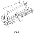
- FIG. 1 shows an ink jet recording apparatus according to a first embodiment of the present invention.
- the ink jet recording cartridge is constructed such that the ink is ejected onto the recording material such as a sheet of paper or plastic thin material from a recording cartridge 1. thus effecting the recording operation.
- the recording cartridge is detachably mountable on a carriage 3.
- the carriage 3 is supported and guided on a guide rail 4 for reciprocal movement in the directions indicated by arrows, the guide rail 4 being extended in parallel with the recording material 2.
- the carriage 3 is driven by a motor 5 through a timing belt 8 stretched between pulleys 6 and 7.
- the recording cartridge 1 integrally has recording means (recording head) and an ink container.
- the recording material 2 is fed (sub-scan) by sub-scan rollers 9 and 10 disposed upstream and downstream of a recording position with respect to the sheet sub-scan direction, through a position where the recording material is faced to the ink ejection outlets of the recording cartridge 1. While the carriage 3 moves (main scan) along the recording material 2, the ink ejector of the recording head 1 is driven in accordance with an image forming apparatus to effect the recording for one line. After completion of the recording of one line, the sub-scan rollers 9 and 10 are rotated through a predetermined amount to feed the recording material 2 in the direction indicated by an arrow (sub-scan). By repeating the main scan and the sub-scan alternately, the recording is effected over the entire surface of the recording material 2.
- a recovery mechanism 11 to assure the stabilized ink ejection of the recording head of the recording cartridge 1 and to prevent solidification of the ink after the apparatus is left unused for a long period of time.
- a cap 12 for hermetically sealing or capping the ink ejector during non-recording.
- the cap 12 is made of elastic rubber to assure the hermetical sealing.
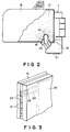
- FIG. 2 is a partly broken side view of a recording cartridge 1.
- the recording cartridge 1 is in the form of a unit integrally having a recording means (recording head) 15 and an ink container 16 which is detachably mountable to the recording means.
- the ink container 16 In the ink container 16, there is accommodated an ink absorbing material, and the ink is absorbed and retained in the ink absorbing material 17.
- the ink absorbing 17 is in the form of a porous sponge having an elasticity. It can absorb and retain the ink by the capillary function of the porous material.
- the recording head 15 is provided with an ink supply passage 18 for supplying the ink from the ink absorbing material 17 into the recording head 15.
- an ink supply passage 18 for supplying the ink from the ink absorbing material 17 into the recording head 15.
- a filter 19 abutted to the ink absorbing material 16 at the end of the ink absorbing material 17.
- the filter 19 functions to remove small foreign matters in the ink to be supplied, and is also effective to prevent introduction of fine bubbles into a communication port 20 in the ink passage 18.
- the recording head 15 is an ink jet recording means for ejecting the ink using thermal energy, and is provided with electrothermal transducers for producing thermal energy.
- the recording head 15 ejects the ink using pressure change caused by expansion and collapse of a bubble due to film boiling of the ink caused by the thermal energy applied by the electrothermal transducer. By the ejection ink, the recording is effected.
- Figure 3 is a partial perspective view illustrating the structure of the ink ejecting portion of the recording head 15.
- a predetermined gap therebetween (approx. 0.5 - 2.0 mm, for example)
- an electrothermal transducer (heat generating resistor or the like) 25 for generating ink ejection energy is disposed.
- the recording cartridge 1 having the recording head 15 is carried on a carriage 3 with such a positional relationship that the array of the ejection outlets 22 extends in a direction crossing with a main scan direction.
- the electrothermal transducers corresponding to the ejection signals or image signals are driven (electric energy supply), by which the ink in the liquid passage 24 is film-boiled, and by the pressure produced at that time is effective to ejected ink through the ejection outlets 22.
- the filter 19 press-contacted to the ink absorbing material 12 at an end of the ink supply passage 18 has a configuration projecting into the ink absorbing material 17. More particularly, in the case of the filter 17 according to the first embodiment shown in Figure 2, the configuration of the projected portion is semi-spherical or less-than-semi-spherical. Therefore, the end of the ink passage 18 and the filter 19 depresses into the ink absorbing material 17, by which the density of the ink absorbing material at the ink supply portion (adjacent to the ink supply passage 18) is increased, and the close contactness between the filter 19 and the ink absorbing material 17, is enhanced.
- the ink in the ink absorbing material 17 tends to be concentrated to the neighborhood of the ink supply passage 18, because the density there is high, and therefore, the capillary force is high there, and in addition, the introduction of the air into the interface between the filter 19 and the ink absorbing material 17 can be effectively prevented.
- the filter 19 is in the form of a semi-spherical and projects into the ink absorbing material 17, and the end portion of the communication port 20 of the ink supply passage 18 has a diverging configuration with which the cross-sectional area increases toward the ink absorbing material 17.
- the filter 19 and the ink absorbing material 17 are closely contacted with each other, and in addition, the sufficient press-contact force can be provided, and therefore, the air bubbles moving in accordance with the ink flow are trapped by the filter 19 and the ink absorbing material 17 having an increased density, so that the introduction into the communication port 20 of the ink supply passage 18 can be prevented.
- the spherical filter 19 is reinforced by the pressure of the ink absorbing material 17, and therefore, it can maintain its configuration without deformation, and therefore, the above-described advantageous effects can be maintained stably.
- the filter 19 is in contact with the ink absorbing material with a contact area which is larger than the cross-sectional area of the ink supply passage, and therefore, the ink supply area is increased, the enhancing in the ink supply performance.
- the density of the ink absorbing material 17 can be enhanced.
- the gap between the ink absorbing material 17 and the ink supply passage 18 becomes large with the result of difficulty in preventing air introduction. According to this embodiment, however, this does not occur, and the introduction of the air into between the ink absorbing material 17 and the ink supply passage 19 and the air introduction from the filter 19 to the ink supply passage 18 (communication port 20) can be assuredly prevented.
- the ink can be properly and stably supplied until the remaining quantity of the ink becomes zero or very small, and in addition, the ink can be stably and properly ejected.
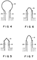
- Figures 4 - 10 show another embodiments having different filters 19.
- the configuration of the projected portion of the filter 19 is closer to the spherical shape, thus increasing the surface area of the filter 19.
- the surface area of the filter 19 is large, and therefore, the resistance against the ink flow can be further lowered.
- the contact-pressure (close-contact force) between the filter 19 and the ink absorbing material 17 can be further increased.
- Figure 5 shows a third embodiment in which the projected filter 19 has a frusto-conical configuration.
- Figure 6 shows a fourth embodiment, in which the projected portion of the filter 19 has a frusto-conical configuration.
- This structure is effective to prevent pressure concentration at an apex of the filter 19, so that a permanent deformation of the ink absorbing material 17 press-contacted thereto can be prevented, and therefore, the pressure contact force (close-contactness) between the filter 19 and the ink absorbing material 17 can be stabilized.
- FIG 7 there is shown a fifth embodiment, in which the filter 19 has a paraboloid configuration.
- the advantageous effects of both of the frusto-conical filter of Figure 6 and the spherical filter of Figure 4, can be provided.
- the pressure distribution at the contact portion of the ink absorbing material 19 can be made uniform, and the resistance against the deformation of the filter 19 can be enhanced.
- Figure 8 shows a sixth embodiment, in which a reinforcing member 26 is disposed along the inside surface of the filter 19.
- the reinforcing member functions to increase the durability against deformation of the filter 19 to prevent collapse of the filter 19, and it can be provided by a member constituting the ink supply passage 18 for another member.
- Figure 9 shows a seventh embodiment, in which the entirety including the ink supply passage 18 is constituted by the filter 19, and along the inside surface of the filter 19, a reinforcing member 26 is disposed.
- the part of the ink passage 18 is eliminated, and the entirety is constituted by the filter 19.
- the area of the filter 19 can be increased, thus decreasing the resistance against the ink flow.
- Figure 10 shows an eighth embodiment which is a modification of the first embodiment of Figure 2, but the area of the filter 19 is decreased.
- the surface of the end portion of the ink supply passage 18 is generally converged by the converging surface 27.
- the filter 19 is bonded to provide a continuous surface. With this structure, by decreasing the area of the filter 19, it is possible to decrease the cost.
- the pressure distribution of the portion contacting the ink absorbing material 17 can be made smooth.
- the filter 19 and the ink absorbing material 17 are closely contacted, and sufficient pressure contact force can be provided.
- the air bubbles moving with the ink flow are trapped by the filter 19 and the ink absorbing material 17 having an increased density, so that they are prevented from entering the communication port 20 of the ink supply passage.
- the filter 19 is enhanced by the pressure of the ink absorbing material 17, and the initial configuration can be maintained without deformation, and the above-described advantageous effects can be stably maintained.
- the gap between the ink absorbing material 17 and the ink supply passage 18 can be eliminated, and the introduction of the air can be further effectively prevented.
- the ink in the ink absorbing material 17 tends to concentrate to the neighborhood of the ink supply passage 18 having high density and therefore high capillary force, and in addition, the introduction of the air at the interface between the filter 19 and the ink absorbing material 17 can be effectively prevented. In addition, the air introduction from the filter 19 into the ink supply passage 18 (communication port 20) can be assuredly prevented. In this manner, stabilized and proper ink supply can be carried out until the remaining amount of the ink becomes zero or minimum, and the proper ink ejection can be accomplished.
- the present invention is similarly applicable to a line type ink jet recording apparatus having a recording width covering a part or entirety of the width of the recording material.
- the ink jet recording apparatus comprises one recording cartridge, but the present invention is applicable to a color ink jet recording apparatus using a plurality of recording means to effect the recording with different full colors, or an ink jet recording apparatus using plural recording means containing same color but different density inks.
- the present invention is applicable irrespective of the number of recording means (recording cartridge) with the same advantageous effects.
- An ink jet recording apparatus to which the present invention is applicable may comprise a recording head using electromechanical converters such as piezoelectric elements.
- an ink jet recording apparatus ejecting the ink using thermal energy is most preferable. In this case, a high density and fine image can be produced.
- the present invention is particularly suitably usable in an ink jet recording head and recording apparatus wherein thermal energy by an electrothermal transducer, laser beam or the like is used to cause a change of state of the ink to eject or discharge the ink. This is because the high density of the picture elements and the high resolution of the recording are possible.
- the typical structure and the operational principle are preferably the ones disclosed in U.S. Patent Nos. 4,723,129 and 4,740,796.
- the principle and structure are applicable to a so-called on-demand type recording system and a continuous type recording system.
- it is suitable for the on-demand type because the principle is such that at least one driving signal is applied to an electrothermal transducer disposed on a liquid (ink) retaining sheet or liquid passage, the driving signal being enough to provide such a quick temperature rise beyond a departure from nucleation boiling point, by which the thermal energy is provided by the electrothermal transducer to produce film boiling on the heating portion of the recording head, whereby a bubble can be formed in the liquid (ink) corresponding to each of the driving signals.
- the liquid (ink) is ejected through an ejection outlet to produce at least one droplet.
- the driving signal is preferably in the form of a pulse, because the development and contraction of the bubble can be effected instantaneously, and therefore, the liquid (ink) is ejected with quick response.
- the driving signal in the form of the pulse is preferably such as disclosed in U.S. Patents Nos. 4,463,359 and 4,345,262.
- the temperature increasing rate of the heating surface is preferably such as disclosed in U.S. Patent No. 4,313,124.
- the structure of the recording head may be as shown in U.S. Patent Nos. 4,558,333 and 4,459,600 wherein the heating portion is disposed at a bent portion, as well as the structure of the combination of the ejection outlet, liquid passage and the electrothermal transducer as disclosed in the above-mentioned patents.
- the present invention is applicable to the structure disclosed in Japanese Laid-Open Patent Application No. 123670/1984 wherein a common slit is used as the ejection outlet for plural electrothermal transducers, and to the structure disclosed in Japanese Laid-Open Patent Application No. 138461/1984 wherein an opening for absorbing pressure wave of the thermal energy is formed corresponding to the ejecting portion. This is because the present invention is effective to perform the recording operation with certainty and at high efficiency irrespective of the type of the recording head.
- the provisions of the recovery means and/or the auxiliary means for the preliminary operation are preferable, because they can further stabilize the effects of the present invention.
- preliminary heating means which may be the electrothermal transducer, an additional heating element or a combination thereof.
- means for effecting preliminary ejection (not for the recording operation) can stabilize the recording operation.
- the ink jet recording apparatus may be used as an output terminal of an information processing apparatus such as computer or the like, as a copying apparatus combined with an image reader or the like, or as a facsimile machine having information sending and receiving functions.
- An ink jet cartridge includes a head portion; an ink container portion; an ink passage for supplying ink from the ink container portion to the head portion; ink absorbing material in the ink container; and a filter press-contacted to the ink container; a filter press-contacted to the ink absorbing material adjacent an end of the ink passage, the filter having an area larger than a cross-sectional area of the ink passage.
Abstract
Description
- The present invention relates to an ink jet cartridge and an ink jet apparatus usable with the ink jet cartridge wherein a recording head and a ink container are integral.
- In the ink jet type recording apparatus, the ink is ejected onto a recording material from a recording means (recording head) in accordance with a image signal. It is advantageous in that the size of the recording means can be reduced, that fine images can be recorded at a high speed, that plain paper is usable without special treatment therefor, that the running cost is low, that the noise is small because it is non-impact type, and that it is easy to effect the color image recording with the use of a plurality of different color inks. Among them, a full-multiple recording means having a great number of ejection outlets arranged in the direction of the with of the sheet, is advantageous because the recording speed can be further increased. Particularly, an ink jet type recording means (recording head) which ejects the ink using thermal energy can be easily manufactured with high density liquid passages (ejection outlets), since it can be manufactured by etching, evaporation, spattering or another semiconductor manufacturing process to manufacture electrothermal transducers, electrodes, liquid passages and top plate, the electrothermal transducers and electrodes are formed as films on a substrate. In addition, a high resolution image can be recorded at a high speed with simple an compact structure. On the other hand, various materials for the recording material are desired to be used. Recently, in addition to the usual plain paper or thin resin sheet (OHP sheet or the like), a thin sheet of paper or processed sheet (the sheet having perforations for the filing, the sheets with cutting perforations, or non-rectangular sheet), are desired to be used with printers.
- In one type of ink jet recording apparatus, an ink supply tube is connected to a recording head carried on a carriage of the recording apparatus to supply the ink thereto from an exchangeable type ink cartridge. In the other type of the apparatus, an integral recording head and ink container, is detachably mounted on the carriage of the apparatus.
- In the latter case (ink jet cartridge), is particularly suitable for personal use because of the small size, low cost and easy handling.
- In the ink jet cartridge type, the recording head and the ink container communicate with each other by insertion of an ink supply pipe of the recording head into the ink container. There are two types from the standpoint of the ink container. In the first type, liquid ink is accommodated in an elastic bladder, and in the other type, the ink is contained in an ink absorbing material. In either of the types of the ink jet cartridge, the ink supply passage is provided with a filter to prevent introduction of foreign manner and bubbles into the recording head. In the case of the ink container having therein an ink absorbing material, the configuration of the ink supply passage and the configuration of the filter, have been determined without consideration to the elastic property of the ink absorbing material or to the ink supply mechanism, and therefore, the ink therein becomes non-usable despite a great amount of ink remaining therein. For example, the filter is flat or concave. In these cases, the contact pressure between the filter and the ink absorbing material is not enough with the result of air space around the filter surface or lower capillary force due to the density decrease of the ink absorbing material. If this occurs, the ink is not easily supplied to the supply portion. As a result, the resistance against the flow of the ink at the supply part becomes large with the result of disturbance to the ink ejection due to the insufficient ink supply, even to such a extent that the ink supply becomes impossible despite a large amount of ink remaining in the container. If this occurs, the ink is no longer ejected.
- In the recording cartridge used in the conventional ink jet recording apparatus, the filter constitutes a flat or concave surface, and the ink passage is straight. This structure involves the following problems. First, the configuration of the filter becomes concave, or the concavity is enhanced by the pressure of the ink absorbing material. Second, the pressure of the ink absorbing material is maximum at corners of the ink passage with the result of reduction of the contact pressure at the filter surface and permanent deformation of the ink absorbing material. Third, since the ink supply passage is straight, the ink absorbing material adjacent the base portion of the ink supply passage is separated from the inside surface of the ink container by the insertion of the ink supply pipe with the result that air is introduced through the clearance formed between the surface and the deformed ink absorbing material.
- If this situation occurs, the ink supply becomes insufficient due to the increase of the resistance against ink flow at the ink supply portion with the result of disturbance to the ink ejection. Or, an air layer completely blocking the ink flow is formed at the filter, disabling the ink supply. If this occurs, the ink is no longer ejected despite a great amount of ink remaining in the container.
- Accordingly, it is a principal object of the present invention to provide an ink jet cartridge and an ink jet recording apparatus using the same in which the ink can be supplied in the proper stabilized manner until no or only small amount of ink remains in the container, thus stabilizing the ink ejection.
- According to an aspect of the present invention, there is provided an ink jet cartridge comprising: a head portion; an ink container portion; an ink passage for supplying ink from the ink container portion to the head portion; ink absorbing material in the ink container; and a filter press-contacted to the ink container; a filter press-contacted to the ink absorbing material adjacent an end of the ink passage, the filter having an area larger than a cross-sectional area of the ink passage.
- According to another aspect of the present invention, there is provided an ink jet recording apparatus for ejecting ink from recording means onto a recording material, in which the recording means and an ink container constitute an integral unit, comprising a filter press-contacted to the ink absorbing material at an ink supply passage for supplying the ink from the absorbing material in the ink container to the recording means, wherein the filter has a convex configuration toward the ink absorbing material.
- These and other objects, features and advantages of the present invention will become more apparent upon a consideration of the following description of the preferred embodiments of the present invention taken in conjunction with the accompanying drawings.
- Figure 1 is a schematic perspective view of an ink jet recording apparatus according to a first embodiment of the present invention.
- Figure 2 is a partly broken side view of an ink jet cartridge according to the first embodiment.
- Figure 3 is a partial perspective view of an ink ejection outlet of the recording means of Figure 2.
- Figure 4 is a partial longitudinal sectional view of a filter in Figure 2 according to a second embodiment of the present invention.
- Figure 5 is a partial longitudinal sectional view of the filter in Figure 2 according to a third embodiment of the present invention.
- Figure 6 is a partial longitudinal sectional view of the filter in Figure 2 according to a fourth embodiment of the present invention.
- Figure 7 is a partial longitudinal sectional view of the filter in Figure 2 according to a fifth embodiment of the present invention.
- Figure 8 is a partial longitudinal sectional view of a filter in Figure 2 according to a sixth embodiment of the present invention.
- Figure 9 is a partial longitudinal sectional view of a filter in Figure 2 according to a seventh embodiment of the present invention.
- Figure 10 is a partial longitudinal sectional view of the filter in Figure 2 according to an eighth embodiment of the present invention.
- Referring to the accompanying drawings, the embodiments of the present invention will be described.
- Figure 1 shows an ink jet recording apparatus according to a first embodiment of the present invention. In this Figure, the ink jet recording cartridge is constructed such that the ink is ejected onto the recording material such as a sheet of paper or plastic thin material from a recording cartridge 1. thus effecting the recording operation. The recording cartridge is detachably mountable on a
carriage 3. Thecarriage 3 is supported and guided on aguide rail 4 for reciprocal movement in the directions indicated by arrows, theguide rail 4 being extended in parallel with therecording material 2. Thecarriage 3 is driven by a motor 5 through atiming belt 8 stretched betweenpulleys - The
recording material 2 is fed (sub-scan) bysub-scan rollers carriage 3 moves (main scan) along therecording material 2, the ink ejector of the recording head 1 is driven in accordance with an image forming apparatus to effect the recording for one line. After completion of the recording of one line, thesub-scan rollers recording material 2 in the direction indicated by an arrow (sub-scan). By repeating the main scan and the sub-scan alternately, the recording is effected over the entire surface of therecording material 2. - Referring to Figure 1, at a position within the movable range of the recording cartridge 1 and outside the recording region, there is disposed a recovery mechanism 11 to assure the stabilized ink ejection of the recording head of the recording cartridge 1 and to prevent solidification of the ink after the apparatus is left unused for a long period of time. At the front side of the recovery mechanism 11, there is a
cap 12 for hermetically sealing or capping the ink ejector during non-recording. Usually, thecap 12 is made of elastic rubber to assure the hermetical sealing. - Figure 2 is a partly broken side view of a recording cartridge 1. In this Figure, the recording cartridge 1 is in the form of a unit integrally having a recording means (recording head) 15 and an
ink container 16 which is detachably mountable to the recording means. In theink container 16, there is accommodated an ink absorbing material, and the ink is absorbed and retained in theink absorbing material 17. The ink absorbing 17 is in the form of a porous sponge having an elasticity. It can absorb and retain the ink by the capillary function of the porous material. - The
recording head 15 is provided with anink supply passage 18 for supplying the ink from theink absorbing material 17 into therecording head 15. At an end of theink supply passage 18, there is provided afilter 19 abutted to theink absorbing material 16 at the end of theink absorbing material 17. Thefilter 19 functions to remove small foreign matters in the ink to be supplied, and is also effective to prevent introduction of fine bubbles into acommunication port 20 in theink passage 18. - The
recording head 15 is an ink jet recording means for ejecting the ink using thermal energy, and is provided with electrothermal transducers for producing thermal energy. Therecording head 15 ejects the ink using pressure change caused by expansion and collapse of a bubble due to film boiling of the ink caused by the thermal energy applied by the electrothermal transducer. By the ejection ink, the recording is effected. - Figure 3 is a partial perspective view illustrating the structure of the ink ejecting portion of the
recording head 15. In this Figure, in theejection side surface 21 faced to therecording material 2 with a predetermined gap therebetween (approx. 0.5 - 2.0 mm, for example), is provided with a plurality ofejection outlets 22 at a predetermined pitch. Along a wall of each of thepassages 24 in communication with theejection outlet 22 and thecommon liquid chamber 23, an electrothermal transducer (heat generating resistor or the like) 25 for generating ink ejection energy is disposed. In this embodiment, the recording cartridge 1 having therecording head 15 is carried on acarriage 3 with such a positional relationship that the array of theejection outlets 22 extends in a direction crossing with a main scan direction. The electrothermal transducers corresponding to the ejection signals or image signals, are driven (electric energy supply), by which the ink in theliquid passage 24 is film-boiled, and by the pressure produced at that time is effective to ejected ink through theejection outlets 22. - In Figure 2, the
filter 19 press-contacted to theink absorbing material 12 at an end of theink supply passage 18 has a configuration projecting into theink absorbing material 17. More particularly, in the case of thefilter 17 according to the first embodiment shown in Figure 2, the configuration of the projected portion is semi-spherical or less-than-semi-spherical. Therefore, the end of theink passage 18 and thefilter 19 depresses into theink absorbing material 17, by which the density of the ink absorbing material at the ink supply portion (adjacent to the ink supply passage 18) is increased, and the close contactness between thefilter 19 and theink absorbing material 17, is enhanced. - According to the structure of the
ink supply passage 18 and thefilter 19 of Figure 2, the ink in theink absorbing material 17 tends to be concentrated to the neighborhood of theink supply passage 18, because the density there is high, and therefore, the capillary force is high there, and in addition, the introduction of the air into the interface between thefilter 19 and theink absorbing material 17 can be effectively prevented. In the example shown in the Figure, thefilter 19 is in the form of a semi-spherical and projects into theink absorbing material 17, and the end portion of thecommunication port 20 of theink supply passage 18 has a diverging configuration with which the cross-sectional area increases toward theink absorbing material 17. By these structure, the occurrence of gap due to the deformation of theink absorbing material 17 is minimized, thus decreasing the factor of the air introduction. Thefilter 19 may be fixed to theink absorbing material 17 by heat fusing or bonding agent or the like. - According to the first embodiment shown in Figure 2, the
filter 19 and theink absorbing material 17 are closely contacted with each other, and in addition, the sufficient press-contact force can be provided, and therefore, the air bubbles moving in accordance with the ink flow are trapped by thefilter 19 and theink absorbing material 17 having an increased density, so that the introduction into thecommunication port 20 of theink supply passage 18 can be prevented. Thespherical filter 19 is reinforced by the pressure of theink absorbing material 17, and therefore, it can maintain its configuration without deformation, and therefore, the above-described advantageous effects can be maintained stably. Furthermore, since the configuration of the end portion of thecommunication port 20 of the ink supply passage 28 is diverging, the clearance betweenink absorbing material 17 and theink supply passage 19 can be eliminated, thus effectively preventing introduction of the air. In addition, thefilter 19 is in contact with the ink absorbing material with a contact area which is larger than the cross-sectional area of the ink supply passage, and therefore, the ink supply area is increased, the enhancing in the ink supply performance. - By increasing the length of the
ink supply passage 18, the density of theink absorbing material 17 can be enhanced. However, with such a structure, the gap between theink absorbing material 17 and theink supply passage 18 becomes large with the result of difficulty in preventing air introduction. According to this embodiment, however, this does not occur, and the introduction of the air into between theink absorbing material 17 and theink supply passage 19 and the air introduction from thefilter 19 to the ink supply passage 18 (communication port 20) can be assuredly prevented. In this manner, according to the first embodiment shown in Figure 2, the ink can be properly and stably supplied until the remaining quantity of the ink becomes zero or very small, and in addition, the ink can be stably and properly ejected. Figures 4 - 10 show another embodiments havingdifferent filters 19. In the second embodiment shown in Figure 4, the configuration of the projected portion of thefilter 19 is closer to the spherical shape, thus increasing the surface area of thefilter 19. With this structure, the surface area of thefilter 19 is large, and therefore, the resistance against the ink flow can be further lowered. In addition, the contact-pressure (close-contact force) between thefilter 19 and theink absorbing material 17 can be further increased. - Figure 5 shows a third embodiment in which the projected
filter 19 has a frusto-conical configuration. With this structure, when the length of theink supply passage 18 is long or when the elasticity of theink absorbing material 17 is high, the pressure distribution at the contact portion between theink supply passage 18 and theink absorbing material 17 may be concentrated along the length of theink supply passage 17; and even in that case, the strength of thefilter 19 can be increased. - Figure 6 shows a fourth embodiment, in which the projected portion of the
filter 19 has a frusto-conical configuration. This structure is effective to prevent pressure concentration at an apex of thefilter 19, so that a permanent deformation of theink absorbing material 17 press-contacted thereto can be prevented, and therefore, the pressure contact force (close-contactness) between thefilter 19 and theink absorbing material 17 can be stabilized. - Referring to Figure 7, there is shown a fifth embodiment, in which the
filter 19 has a paraboloid configuration. With this structure, the advantageous effects of both of the frusto-conical filter of Figure 6 and the spherical filter of Figure 4, can be provided. In other words, the pressure distribution at the contact portion of theink absorbing material 19 can be made uniform, and the resistance against the deformation of thefilter 19 can be enhanced. - Figure 8 shows a sixth embodiment, in which a reinforcing
member 26 is disposed along the inside surface of thefilter 19. The reinforcing member functions to increase the durability against deformation of thefilter 19 to prevent collapse of thefilter 19, and it can be provided by a member constituting theink supply passage 18 for another member. - Figure 9 shows a seventh embodiment, in which the entirety including the
ink supply passage 18 is constituted by thefilter 19, and along the inside surface of thefilter 19, a reinforcingmember 26 is disposed. As compared with the foregoing embodiment, the part of theink passage 18 is eliminated, and the entirety is constituted by thefilter 19. With this structure, the area of thefilter 19 can be increased, thus decreasing the resistance against the ink flow. - Figure 10 shows an eighth embodiment which is a modification of the first embodiment of Figure 2, but the area of the
filter 19 is decreased. In addition, the surface of the end portion of theink supply passage 18 is generally converged by the convergingsurface 27. Correspondingly, thefilter 19 is bonded to provide a continuous surface. With this structure, by decreasing the area of thefilter 19, it is possible to decrease the cost. In addition, the pressure distribution of the portion contacting theink absorbing material 17 can be made smooth. - According to the foregoing embodiments, the
filter 19 and theink absorbing material 17 are closely contacted, and sufficient pressure contact force can be provided. The air bubbles moving with the ink flow are trapped by thefilter 19 and theink absorbing material 17 having an increased density, so that they are prevented from entering thecommunication port 20 of the ink supply passage. In addition, thefilter 19 is enhanced by the pressure of theink absorbing material 17, and the initial configuration can be maintained without deformation, and the above-described advantageous effects can be stably maintained. Furthermore, the gap between theink absorbing material 17 and theink supply passage 18 can be eliminated, and the introduction of the air can be further effectively prevented. - The ink in the
ink absorbing material 17 tends to concentrate to the neighborhood of theink supply passage 18 having high density and therefore high capillary force, and in addition, the introduction of the air at the interface between thefilter 19 and theink absorbing material 17 can be effectively prevented. In addition, the air introduction from thefilter 19 into the ink supply passage 18 (communication port 20) can be assuredly prevented. In this manner, stabilized and proper ink supply can be carried out until the remaining amount of the ink becomes zero or minimum, and the proper ink ejection can be accomplished. - In the foregoing description, a serial type ink jet recording apparatus has been taken in which the
recording material 2 is scanned in the main scan direction. However, the present invention is similarly applicable to a line type ink jet recording apparatus having a recording width covering a part or entirety of the width of the recording material. In the foregoing, the ink jet recording apparatus comprises one recording cartridge, but the present invention is applicable to a color ink jet recording apparatus using a plurality of recording means to effect the recording with different full colors, or an ink jet recording apparatus using plural recording means containing same color but different density inks. Thus, the present invention is applicable irrespective of the number of recording means (recording cartridge) with the same advantageous effects. - An ink jet recording apparatus to which the present invention is applicable may comprise a recording head using electromechanical converters such as piezoelectric elements. However, an ink jet recording apparatus ejecting the ink using thermal energy is most preferable. In this case, a high density and fine image can be produced.
- The present invention is particularly suitably usable in an ink jet recording head and recording apparatus wherein thermal energy by an electrothermal transducer, laser beam or the like is used to cause a change of state of the ink to eject or discharge the ink. This is because the high density of the picture elements and the high resolution of the recording are possible.
- The typical structure and the operational principle are preferably the ones disclosed in U.S. Patent Nos. 4,723,129 and 4,740,796. The principle and structure are applicable to a so-called on-demand type recording system and a continuous type recording system. Particularly, however, it is suitable for the on-demand type because the principle is such that at least one driving signal is applied to an electrothermal transducer disposed on a liquid (ink) retaining sheet or liquid passage, the driving signal being enough to provide such a quick temperature rise beyond a departure from nucleation boiling point, by which the thermal energy is provided by the electrothermal transducer to produce film boiling on the heating portion of the recording head, whereby a bubble can be formed in the liquid (ink) corresponding to each of the driving signals. By the production, development and contraction of the the bubble, the liquid (ink) is ejected through an ejection outlet to produce at least one droplet. The driving signal is preferably in the form of a pulse, because the development and contraction of the bubble can be effected instantaneously, and therefore, the liquid (ink) is ejected with quick response. The driving signal in the form of the pulse is preferably such as disclosed in U.S. Patents Nos. 4,463,359 and 4,345,262. In addition, the temperature increasing rate of the heating surface is preferably such as disclosed in U.S. Patent No. 4,313,124.
- The structure of the recording head may be as shown in U.S. Patent Nos. 4,558,333 and 4,459,600 wherein the heating portion is disposed at a bent portion, as well as the structure of the combination of the ejection outlet, liquid passage and the electrothermal transducer as disclosed in the above-mentioned patents. In addition, the present invention is applicable to the structure disclosed in Japanese Laid-Open Patent Application No. 123670/1984 wherein a common slit is used as the ejection outlet for plural electrothermal transducers, and to the structure disclosed in Japanese Laid-Open Patent Application No. 138461/1984 wherein an opening for absorbing pressure wave of the thermal energy is formed corresponding to the ejecting portion. This is because the present invention is effective to perform the recording operation with certainty and at high efficiency irrespective of the type of the recording head.
- The provisions of the recovery means and/or the auxiliary means for the preliminary operation are preferable, because they can further stabilize the effects of the present invention. As for such means, there are capping means for the recording head, cleaning means therefor, pressing or sucking means, preliminary heating means which may be the electrothermal transducer, an additional heating element or a combination thereof. Also, means for effecting preliminary ejection (not for the recording operation) can stabilize the recording operation.
- The ink jet recording apparatus may be used as an output terminal of an information processing apparatus such as computer or the like, as a copying apparatus combined with an image reader or the like, or as a facsimile machine having information sending and receiving functions.
- While the invention has been described with reference to the structures disclosed herein, it is not confined to the details set forth and this application is intended to cover such modifications or changes as may come within the purposes of the improvements or the scope of the following claims.
- An ink jet cartridge includes a head portion; an ink container portion; an ink passage for supplying ink from the ink container portion to the head portion; ink absorbing material in the ink container; and a filter press-contacted to the ink container; a filter press-contacted to the ink absorbing material adjacent an end of the ink passage, the filter having an area larger than a cross-sectional area of the ink passage.
Claims (16)
- An ink jet cartridge comprising;
a head portion;
an ink container portion;
an ink passage for supplying ink from said ink container portion to said head portion;
ink absorbing material in said ink container; and
a filter press-contacted to said ink container;
a filter press-contacted to said ink absorbing material adjacent an end of said ink passage, said filter having an area larger than a cross-sectional area of said ink passage. - A cartridge according to Claim 1, wherein said filter has a projected configuration of one or less than one half of a sphere.
- A cartridge according to Claim 1, wherein said filter has a projected configuration of more than one half of sphere.
- A cartridge according to Claim 1, wherein said filter has a projected configuration of a cone.
- A cartridge according to Claim 1, wherein said filter has a projected configuration of a part cone.
- A cartridge according to Claim 1, wherein said filter has a projected configuration of paraboloid.
- A cartridge according to Claim 7, wherein said ink passage functions as said filter.
- A cartridge according to Claim 7, wherein a reinforcing member is provided in said filter.
- A cartridge according to Claim 1, wherein said ink passage is diverging toward said ink absorbing material.
- A cartridge according to Claim 1, wherein an outer surface of a member defining said ink passage converges toward said ink absorbing material to a surface smoothly continuing to said filter.
- A cartridge according to Claim 1, wherein a reinforcing member is provided along an inner side of said filter.
- A cartridge according to Claim 1, wherein said recording head is provided with an electrothermal transducer for producing thermal energy to eject the ink.
- A cartridge according to Claim 12, wherein said electrothermal transducer produces film boiling of the ink.
- An ink jet apparatus, comprising:
a head portion;
an ink container portion;
an ink passage for supplying ink from said ink container portion to said head portion;
ink absorbing material in said ink container; and
a filter press-contacted to said ink container;
a filter press-contacted to said ink absorbing material adjacent an end of said ink passage, said filter having an area larger than a cross-sectional area of said ink passage. - An apparatus according to Claim 14, wherein said recording head is provided with an electrothermal transducer for producing thermal energy to eject the ink.
- An apparatus according to Claim 15, wherein said electrothermal transducer produces film boiling of the ink.
Applications Claiming Priority (2)
| Application Number | Priority Date | Filing Date | Title |
|---|---|---|---|
| JP181798/92 | 1992-06-16 | ||
| JP18179892A JP3148005B2 (en) | 1992-06-16 | 1992-06-16 | Recording cartridge and ink jet recording apparatus |
Publications (3)
| Publication Number | Publication Date |
|---|---|
| EP0574888A2 true EP0574888A2 (en) | 1993-12-22 |
| EP0574888A3 EP0574888A3 (en) | 1994-06-29 |
| EP0574888B1 EP0574888B1 (en) | 1997-11-12 |
Family
ID=16107048
Family Applications (1)
| Application Number | Title | Priority Date | Filing Date |
|---|---|---|---|
| EP93109559A Expired - Lifetime EP0574888B1 (en) | 1992-06-16 | 1993-06-15 | Ink jet cartridge and ink jet apparatus having same |
Country Status (6)
| Country | Link |
|---|---|
| US (1) | US5502479A (en) |
| EP (1) | EP0574888B1 (en) |
| JP (1) | JP3148005B2 (en) |
| AT (1) | ATE160111T1 (en) |
| DE (1) | DE69315124T2 (en) |
| ES (1) | ES2108782T3 (en) |
Cited By (7)
| Publication number | Priority date | Publication date | Assignee | Title |
|---|---|---|---|---|
| EP0603902A2 (en) * | 1992-12-25 | 1994-06-29 | Canon Kabushiki Kaisha | Liquid jet-head and liquid jet apparatus having said liquid jet-head used therefor |
| EP0657291A1 (en) * | 1993-12-07 | 1995-06-14 | Lexmark International, Inc. | Ink jet cartridge |
| GB2299786A (en) * | 1995-04-05 | 1996-10-16 | Seiko Epson Corp | A coupling member for coupling an ink-jet recording head to an ink cartridge wherein a filter arrangement is contained within the coupling member |
| EP0869006A2 (en) * | 1997-04-04 | 1998-10-07 | Seiko Epson Corporation | Ink jet recording apparatus with filter |
| EP1203667A3 (en) * | 2000-11-02 | 2003-03-05 | Canon Kabushiki Kaisha | Liquid ejection recording head |
| KR100510123B1 (en) * | 2002-06-05 | 2005-08-25 | 삼성전자주식회사 | Ink jet cartridge |
| EP2346697A1 (en) * | 2008-10-30 | 2011-07-27 | Hewlett-Packard Development Company, L.P. | Fluid interconnect for fluid ejection system |
Families Citing this family (34)
| Publication number | Priority date | Publication date | Assignee | Title |
|---|---|---|---|---|
| JP3043926B2 (en) * | 1993-08-20 | 2000-05-22 | キヤノン株式会社 | ink cartridge |
| US6170939B1 (en) | 1992-07-31 | 2001-01-09 | Canon Kabushiki Kaisha | Liquid storing container for recording apparatus |
| US6206513B1 (en) * | 1993-06-29 | 2001-03-27 | Canon Kabushiki Kaisha | Ink tank unit, an ink jet cartridge having said ink tank unit and an ink jet apparatus having said ink jet cartridge |
| US5497178A (en) * | 1993-12-10 | 1996-03-05 | Lexmark International, Inc. | Multicolor liquid ink jet print head |
| JP3347559B2 (en) | 1994-12-28 | 2002-11-20 | キヤノン株式会社 | Ink tank, inkjet cartridge, and inkjet recording apparatus |
| US5953030A (en) | 1995-04-24 | 1999-09-14 | Canon Kabushiki Kaisha | Ink container with improved air venting structure |
| US6132036A (en) * | 1995-09-14 | 2000-10-17 | Canon Kabushiki Kaisha | Ink tank, production process of ink tank and ink-jet printing apparatus |
| JP3019768B2 (en) * | 1995-12-28 | 2000-03-13 | 富士ゼロックス株式会社 | Ink jet printer and ink jet recording unit |
| JPH1024573A (en) | 1996-07-09 | 1998-01-27 | Canon Inc | Liquid discharge head, manufacture of liquid discharge head, head cartridge, and liquid discharge device |
| JP3513377B2 (en) | 1996-12-05 | 2004-03-31 | キヤノン株式会社 | Method for filling liquid into liquid container, filling unit for carrying out the method, liquid container manufactured by the method, and liquid ejection recording apparatus |
| DE69913006T2 (en) * | 1998-01-23 | 2004-08-26 | Océ-Technologies B.V. | Ink jet device with filter element |
| EP0931658B1 (en) | 1998-01-23 | 2003-11-26 | Océ-Technologies B.V. | Ink jet device with filter element |
| SG95595A1 (en) | 1998-05-13 | 2003-04-23 | Seiko Epson Corp | Ink cartridge for ink-jet printing apparatus |
| JP2000071477A (en) | 1998-06-17 | 2000-03-07 | Canon Inc | Ink supplying device and ink jet recording head |
| JP2000033713A (en) * | 1998-07-17 | 2000-02-02 | Seiko Epson Corp | Ink jet print head and ink jet printer |
| USD430897S (en) * | 1999-06-11 | 2000-09-12 | Lexmark International, Inc. | Ink cartridge for printer |
| US6390615B1 (en) * | 2000-06-19 | 2002-05-21 | Xerox Corporation | Ink tank with securing means and seal |
| JP4148498B2 (en) * | 2002-02-15 | 2008-09-10 | キヤノン株式会社 | Liquid jet recording head and liquid jet recording apparatus |
| US6935739B2 (en) * | 2002-09-30 | 2005-08-30 | Canon Kabushiki Kaisha | Printing apparatus, printing cartridge, and colorant container |
| US20040202836A1 (en) * | 2002-09-30 | 2004-10-14 | Close Shawn M. | Pre-perforated ink-jet media for printer customization |
| JP4018578B2 (en) * | 2003-03-27 | 2007-12-05 | キヤノン株式会社 | Liquid discharge head cartridge |
| US6998008B2 (en) * | 2003-07-15 | 2006-02-14 | Lexmark International, Inc. | Method and apparatus for attaching an ink jet filter to an ink cartridge |
| US7273275B2 (en) * | 2004-11-29 | 2007-09-25 | Lexmark International, Inc. | Air funneling inkjet printhead |
| JP2009090542A (en) * | 2007-10-09 | 2009-04-30 | Canon Inc | Inkjet recording cartridge |
| CN104118215B (en) * | 2014-07-23 | 2017-03-01 | 中山市领达电子有限公司 | Solution box for jet printer |
| JP6421196B2 (en) * | 2014-11-05 | 2018-11-07 | ギガフォトン株式会社 | Target generating apparatus and filter structure manufacturing method |
| US9914308B2 (en) | 2016-01-08 | 2018-03-13 | Canon Kabushiki Kaisha | Liquid ejection apparatus and liquid ejection head |
| JP6611618B2 (en) | 2016-01-08 | 2019-11-27 | キヤノン株式会社 | Recording apparatus, recording apparatus control method, and program |
| JP6716258B2 (en) | 2016-01-08 | 2020-07-01 | キヤノン株式会社 | Recording device, recording device control method, and program |
| US10005287B2 (en) | 2016-01-08 | 2018-06-26 | Canon Kabushiki Kaisha | Liquid ejection apparatus, liquid ejection head, and method of supplying liquid |
| US9925791B2 (en) | 2016-01-08 | 2018-03-27 | Canon Kabushiki Kaisha | Liquid ejection apparatus and liquid ejection head |
| JP2017209864A (en) | 2016-05-25 | 2017-11-30 | キヤノン株式会社 | Liquid discharge device and liquid discharge head |
| JP2021160204A (en) | 2020-03-31 | 2021-10-11 | キヤノン株式会社 | Recording device |
| KR20220029414A (en) * | 2020-09-01 | 2022-03-08 | 캐논 가부시끼가이샤 | Sealing member, method of manufacturing the same, pressure adjustment mechanism, liquid ejection head, and liquid ejection apparatus |
Citations (6)
| Publication number | Priority date | Publication date | Assignee | Title |
|---|---|---|---|---|
| FR2136531A5 (en) * | 1971-04-19 | 1972-12-22 | Dick Co Ab | |
| EP0261764A1 (en) * | 1986-07-01 | 1988-03-30 | Hewlett-Packard Company | Ink reservoir containing an absorbent foam for an ink jet printing device |
| JPH01133747A (en) * | 1987-11-20 | 1989-05-25 | Canon Inc | Liquid jet recording head |
| EP0320165A1 (en) * | 1987-12-03 | 1989-06-14 | Hewlett-Packard Company | Ink jet pen having improved ink storage and distribution capabilities |
| US4967207A (en) * | 1989-07-26 | 1990-10-30 | Hewlett-Packard Company | Ink jet printer with self-regulating refilling system |
| JPH03293155A (en) * | 1990-04-11 | 1991-12-24 | Canon Inc | Ink jet recording head cartridge and ink jet recording device using the cartridge |
Family Cites Families (13)
| Publication number | Priority date | Publication date | Assignee | Title |
|---|---|---|---|---|
| US3779390A (en) * | 1972-05-18 | 1973-12-18 | Itt | Filter assembly |
| CA1127227A (en) * | 1977-10-03 | 1982-07-06 | Ichiro Endo | Liquid jet recording process and apparatus therefor |
| US4330787A (en) * | 1978-10-31 | 1982-05-18 | Canon Kabushiki Kaisha | Liquid jet recording device |
| US4345262A (en) * | 1979-02-19 | 1982-08-17 | Canon Kabushiki Kaisha | Ink jet recording method |
| US4463359A (en) * | 1979-04-02 | 1984-07-31 | Canon Kabushiki Kaisha | Droplet generating method and apparatus thereof |
| US4313124A (en) * | 1979-05-18 | 1982-01-26 | Canon Kabushiki Kaisha | Liquid jet recording process and liquid jet recording head |
| US4558333A (en) * | 1981-07-09 | 1985-12-10 | Canon Kabushiki Kaisha | Liquid jet recording head |
| JPS5933154A (en) * | 1982-08-19 | 1984-02-22 | Canon Inc | Ink jet recorder |
| JPS59123670A (en) * | 1982-12-28 | 1984-07-17 | Canon Inc | Ink jet head |
| JPS59138461A (en) * | 1983-01-28 | 1984-08-08 | Canon Inc | Liquid jet recording apparatus |
| JPS60234848A (en) * | 1984-05-08 | 1985-11-21 | Canon Inc | Liquid jet recording head |
| JP2845916B2 (en) * | 1989-01-13 | 1999-01-13 | キヤノン株式会社 | Liquid storage container, liquid jet recording head, and liquid discharge recording device |
| JP2575205B2 (en) * | 1989-01-13 | 1997-01-22 | キヤノン株式会社 | Ink tank |
-
1992
- 1992-06-16 JP JP18179892A patent/JP3148005B2/en not_active Expired - Fee Related
-
1993
- 1993-06-15 AT AT93109559T patent/ATE160111T1/en not_active IP Right Cessation
- 1993-06-15 DE DE69315124T patent/DE69315124T2/en not_active Expired - Lifetime
- 1993-06-15 ES ES93109559T patent/ES2108782T3/en not_active Expired - Lifetime
- 1993-06-15 EP EP93109559A patent/EP0574888B1/en not_active Expired - Lifetime
- 1993-06-16 US US08/076,979 patent/US5502479A/en not_active Expired - Lifetime
Patent Citations (6)
| Publication number | Priority date | Publication date | Assignee | Title |
|---|---|---|---|---|
| FR2136531A5 (en) * | 1971-04-19 | 1972-12-22 | Dick Co Ab | |
| EP0261764A1 (en) * | 1986-07-01 | 1988-03-30 | Hewlett-Packard Company | Ink reservoir containing an absorbent foam for an ink jet printing device |
| JPH01133747A (en) * | 1987-11-20 | 1989-05-25 | Canon Inc | Liquid jet recording head |
| EP0320165A1 (en) * | 1987-12-03 | 1989-06-14 | Hewlett-Packard Company | Ink jet pen having improved ink storage and distribution capabilities |
| US4967207A (en) * | 1989-07-26 | 1990-10-30 | Hewlett-Packard Company | Ink jet printer with self-regulating refilling system |
| JPH03293155A (en) * | 1990-04-11 | 1991-12-24 | Canon Inc | Ink jet recording head cartridge and ink jet recording device using the cartridge |
Non-Patent Citations (2)
| Title |
|---|
| PATENT ABSTRACTS OF JAPAN vol. 13, no. 380 (M-863) (3728) 23 August 1989 & JP-A-01 133 747 (CANON) 25 May 1989 * |
| PATENT ABSTRACTS OF JAPAN vol. 16, no. 132 (M-1229) 3 April 1992 & JP-A-03 293 155 (CANON) 24 December 1991 * |
Cited By (19)
| Publication number | Priority date | Publication date | Assignee | Title |
|---|---|---|---|---|
| US5900898A (en) * | 1992-12-25 | 1999-05-04 | Canon Kabushiki Kaisha | Liquid jet head having a contoured and secured filter, liquid jet apparatus using same, and method of immovably securing a filter to a liquid receiving member of a liquid jet head |
| EP0603902A3 (en) * | 1992-12-25 | 1995-02-22 | Canon Kk | Liquid jet-head and liquid jet apparatus having said liquid jet-head used therefor. |
| EP0603902A2 (en) * | 1992-12-25 | 1994-06-29 | Canon Kabushiki Kaisha | Liquid jet-head and liquid jet apparatus having said liquid jet-head used therefor |
| EP0657291A1 (en) * | 1993-12-07 | 1995-06-14 | Lexmark International, Inc. | Ink jet cartridge |
| US5537136A (en) * | 1993-12-07 | 1996-07-16 | Lexmark International, Inc. | Ink jet cartridge including filter inserts |
| GB2299786A (en) * | 1995-04-05 | 1996-10-16 | Seiko Epson Corp | A coupling member for coupling an ink-jet recording head to an ink cartridge wherein a filter arrangement is contained within the coupling member |
| US6814435B1 (en) | 1995-04-05 | 2004-11-09 | Seiko Epson Corporation | Ink-jet recording apparatus |
| FR2733936A1 (en) * | 1995-04-05 | 1996-11-15 | Seiko Epson Corp | INK JET RECORDING APPARATUS |
| GB2299786B (en) * | 1995-04-05 | 1999-05-26 | Seiko Epson Corp | Ink jet recording apparatus |
| US6019465A (en) * | 1995-04-05 | 2000-02-01 | Seiko Epson Corporation | Ink-jet recording apparatus |
| EP0869006A3 (en) * | 1997-04-04 | 1998-11-18 | Seiko Epson Corporation | Ink jet recording apparatus with filter |
| US6196673B1 (en) | 1997-04-04 | 2001-03-06 | Seiko Epson Corporation | Ink-jet recording device |
| EP0869006A2 (en) * | 1997-04-04 | 1998-10-07 | Seiko Epson Corporation | Ink jet recording apparatus with filter |
| EP1203667A3 (en) * | 2000-11-02 | 2003-03-05 | Canon Kabushiki Kaisha | Liquid ejection recording head |
| US6592215B2 (en) | 2000-11-02 | 2003-07-15 | Canon Kabushiki Kaisha | Liquid ejection recording head |
| KR100510123B1 (en) * | 2002-06-05 | 2005-08-25 | 삼성전자주식회사 | Ink jet cartridge |
| EP2346697A1 (en) * | 2008-10-30 | 2011-07-27 | Hewlett-Packard Development Company, L.P. | Fluid interconnect for fluid ejection system |
| EP2346697A4 (en) * | 2008-10-30 | 2011-11-16 | Hewlett Packard Development Co | Fluid interconnect for fluid ejection system |
| US8556399B2 (en) | 2008-10-30 | 2013-10-15 | Hewlett-Packard Development Company, L.P. | Fluid interconnect for fluid ejection system |
Also Published As
| Publication number | Publication date |
|---|---|
| EP0574888B1 (en) | 1997-11-12 |
| US5502479A (en) | 1996-03-26 |
| EP0574888A3 (en) | 1994-06-29 |
| DE69315124D1 (en) | 1997-12-18 |
| JPH05345425A (en) | 1993-12-27 |
| JP3148005B2 (en) | 2001-03-19 |
| ES2108782T3 (en) | 1998-01-01 |
| DE69315124T2 (en) | 1998-04-02 |
| ATE160111T1 (en) | 1997-11-15 |
Similar Documents
| Publication | Publication Date | Title |
|---|---|---|
| EP0574888B1 (en) | Ink jet cartridge and ink jet apparatus having same | |
| EP0419191A1 (en) | Liquid jet recording head and liquid jet recording apparatus having same | |
| JPH06134998A (en) | Ink jet recorder | |
| US5975778A (en) | Recording apparatus having a recording material confining member | |
| JP3100451B2 (en) | Ink jet recording device | |
| JP3110151B2 (en) | Ink jet recording device | |
| JP3113123B2 (en) | Ink jet recording device | |
| EP1078756B1 (en) | Ink jet recording head, ink jet recording head cartridge and ink jet recording apparatus | |
| JP3059312B2 (en) | Recording head, recording cartridge and recording device | |
| JP3017155B2 (en) | Ink jet recording apparatus and cap member used in the apparatus | |
| JP3270664B2 (en) | Ink jet recording apparatus and method of recovering ink jet recording apparatus | |
| JP2722289B2 (en) | Ink jet recording apparatus and recovery apparatus for the recording apparatus | |
| JPH0781076A (en) | Ink jet recording apparatus | |
| JPH0768791A (en) | Ink jet recorder | |
| JP3233368B2 (en) | Recording device | |
| JP3048022B2 (en) | Ink jet recording device | |
| JP3025110B2 (en) | Ink jet recording device | |
| JP3025089B2 (en) | Ink jet recording device | |
| JP3152804B2 (en) | Fluid connection structure and ink jet recording apparatus using the structure | |
| JP3061661B2 (en) | Ink jet recording device | |
| JP2000185414A (en) | Ink jet recording apparatus | |
| JPH04187449A (en) | Ink jet recorder | |
| JPH0781051A (en) | Image forming apparatus | |
| JP2003246075A (en) | Ink tank, inkjet cartridge, and inkjet recorder | |
| JP2001334688A (en) | Inkabsorber for ink jet recorder |
Legal Events
| Date | Code | Title | Description |
|---|---|---|---|
| PUAI | Public reference made under article 153(3) epc to a published international application that has entered the european phase |
Free format text: ORIGINAL CODE: 0009012 |
|
| 17P | Request for examination filed |
Effective date: 19930615 |
|
| AK | Designated contracting states |
Kind code of ref document: A2 Designated state(s): AT BE CH DE DK ES FR GB GR IE IT LI LU NL PT SE |
|
| PUAL | Search report despatched |
Free format text: ORIGINAL CODE: 0009013 |
|
| AK | Designated contracting states |
Kind code of ref document: A3 Designated state(s): AT BE CH DE DK ES FR GB GR IE IT LI LU NL PT SE |
|
| 17Q | First examination report despatched |
Effective date: 19950926 |
|
| GRAG | Despatch of communication of intention to grant |
Free format text: ORIGINAL CODE: EPIDOS AGRA |
|
| GRAH | Despatch of communication of intention to grant a patent |
Free format text: ORIGINAL CODE: EPIDOS IGRA |
|
| GRAH | Despatch of communication of intention to grant a patent |
Free format text: ORIGINAL CODE: EPIDOS IGRA |
|
| GRAA | (expected) grant |
Free format text: ORIGINAL CODE: 0009210 |
|
| AK | Designated contracting states |
Kind code of ref document: B1 Designated state(s): AT BE CH DE DK ES FR GB GR IE IT LI LU NL PT SE |
|
| PG25 | Lapsed in a contracting state [announced via postgrant information from national office to epo] |
Ref country code: GR Free format text: LAPSE BECAUSE OF FAILURE TO SUBMIT A TRANSLATION OF THE DESCRIPTION OR TO PAY THE FEE WITHIN THE PRESCRIBED TIME-LIMIT Effective date: 19971112 Ref country code: DK Free format text: LAPSE BECAUSE OF NON-PAYMENT OF DUE FEES Effective date: 19971112 Ref country code: BE Free format text: LAPSE BECAUSE OF FAILURE TO SUBMIT A TRANSLATION OF THE DESCRIPTION OR TO PAY THE FEE WITHIN THE PRESCRIBED TIME-LIMIT Effective date: 19971112 Ref country code: AT Free format text: LAPSE BECAUSE OF FAILURE TO SUBMIT A TRANSLATION OF THE DESCRIPTION OR TO PAY THE FEE WITHIN THE PRESCRIBED TIME-LIMIT Effective date: 19971112 |
|
| REF | Corresponds to: |
Ref document number: 160111 Country of ref document: AT Date of ref document: 19971115 Kind code of ref document: T |
|
| REG | Reference to a national code |
Ref country code: CH Ref legal event code: EP |
|
| REF | Corresponds to: |
Ref document number: 69315124 Country of ref document: DE Date of ref document: 19971218 |
|
| REG | Reference to a national code |
Ref country code: CH Ref legal event code: NV Representative=s name: BOVARD AG PATENTANWAELTE |
|
| REG | Reference to a national code |
Ref country code: ES Ref legal event code: FG2A Ref document number: 2108782 Country of ref document: ES Kind code of ref document: T3 |
|
| ITF | It: translation for a ep patent filed |
Owner name: SOCIETA' ITALIANA BREVETTI S.P.A. |
|
| PG25 | Lapsed in a contracting state [announced via postgrant information from national office to epo] |
Ref country code: SE Free format text: LAPSE BECAUSE OF FAILURE TO SUBMIT A TRANSLATION OF THE DESCRIPTION OR TO PAY THE FEE WITHIN THE PRESCRIBED TIME-LIMIT Effective date: 19980212 Ref country code: PT Free format text: LAPSE BECAUSE OF FAILURE TO SUBMIT A TRANSLATION OF THE DESCRIPTION OR TO PAY THE FEE WITHIN THE PRESCRIBED TIME-LIMIT Effective date: 19980212 |
|
| ET | Fr: translation filed | ||
| PG25 | Lapsed in a contracting state [announced via postgrant information from national office to epo] |
Ref country code: LU Free format text: LAPSE BECAUSE OF NON-PAYMENT OF DUE FEES Effective date: 19980615 Ref country code: IE Free format text: LAPSE BECAUSE OF NON-PAYMENT OF DUE FEES Effective date: 19980615 |
|
| PLBE | No opposition filed within time limit |
Free format text: ORIGINAL CODE: 0009261 |
|
| STAA | Information on the status of an ep patent application or granted ep patent |
Free format text: STATUS: NO OPPOSITION FILED WITHIN TIME LIMIT |
|
| 26N | No opposition filed | ||
| REG | Reference to a national code |
Ref country code: GB Ref legal event code: IF02 |
|
| REG | Reference to a national code |
Ref country code: CH Ref legal event code: PFA Owner name: CANON KABUSHIKI KAISHA Free format text: CANON KABUSHIKI KAISHA#30-2, 3-CHOME, SHIMOMARUKO, OHTA-KU#TOKYO 146 (JP) -TRANSFER TO- CANON KABUSHIKI KAISHA#30-2, 3-CHOME, SHIMOMARUKO, OHTA-KU#TOKYO 146 (JP) |
|
| PGFP | Annual fee paid to national office [announced via postgrant information from national office to epo] |
Ref country code: CH Payment date: 20110623 Year of fee payment: 19 Ref country code: ES Payment date: 20110607 Year of fee payment: 19 |
|
| PGFP | Annual fee paid to national office [announced via postgrant information from national office to epo] |
Ref country code: GB Payment date: 20110621 Year of fee payment: 19 Ref country code: NL Payment date: 20110615 Year of fee payment: 19 |
|
| PGFP | Annual fee paid to national office [announced via postgrant information from national office to epo] |
Ref country code: IT Payment date: 20110608 Year of fee payment: 19 |
|
| PGFP | Annual fee paid to national office [announced via postgrant information from national office to epo] |
Ref country code: FR Payment date: 20110713 Year of fee payment: 19 |
|
| PGFP | Annual fee paid to national office [announced via postgrant information from national office to epo] |
Ref country code: DE Payment date: 20110630 Year of fee payment: 19 |
|
| REG | Reference to a national code |
Ref country code: NL Ref legal event code: V1 Effective date: 20130101 |
|
| REG | Reference to a national code |
Ref country code: CH Ref legal event code: PL |
|
| REG | Reference to a national code |
Ref country code: CH Ref legal event code: PL |
|
| GBPC | Gb: european patent ceased through non-payment of renewal fee |
Effective date: 20120615 |
|
| PG25 | Lapsed in a contracting state [announced via postgrant information from national office to epo] |
Ref country code: IT Free format text: LAPSE BECAUSE OF NON-PAYMENT OF DUE FEES Effective date: 20120615 |
|
| REG | Reference to a national code |
Ref country code: FR Ref legal event code: ST Effective date: 20130228 |
|
| PG25 | Lapsed in a contracting state [announced via postgrant information from national office to epo] |
Ref country code: CH Free format text: LAPSE BECAUSE OF NON-PAYMENT OF DUE FEES Effective date: 20120630 Ref country code: GB Free format text: LAPSE BECAUSE OF NON-PAYMENT OF DUE FEES Effective date: 20120615 Ref country code: DE Free format text: LAPSE BECAUSE OF NON-PAYMENT OF DUE FEES Effective date: 20130101 Ref country code: NL Free format text: LAPSE BECAUSE OF NON-PAYMENT OF DUE FEES Effective date: 20130101 Ref country code: LI Free format text: LAPSE BECAUSE OF NON-PAYMENT OF DUE FEES Effective date: 20120630 Ref country code: FR Free format text: LAPSE BECAUSE OF NON-PAYMENT OF DUE FEES Effective date: 20120702 |
|
| REG | Reference to a national code |
Ref country code: DE Ref legal event code: R119 Ref document number: 69315124 Country of ref document: DE Effective date: 20130101 |
|
| REG | Reference to a national code |
Ref country code: ES Ref legal event code: FD2A Effective date: 20131018 |
|
| PG25 | Lapsed in a contracting state [announced via postgrant information from national office to epo] |
Ref country code: ES Free format text: LAPSE BECAUSE OF NON-PAYMENT OF DUE FEES Effective date: 20120616 |