EP0574627B1 - Wrist brace - Google Patents
Wrist brace Download PDFInfo
- Publication number
- EP0574627B1 EP0574627B1 EP92305639A EP92305639A EP0574627B1 EP 0574627 B1 EP0574627 B1 EP 0574627B1 EP 92305639 A EP92305639 A EP 92305639A EP 92305639 A EP92305639 A EP 92305639A EP 0574627 B1 EP0574627 B1 EP 0574627B1
- Authority
- EP
- European Patent Office
- Prior art keywords
- lateral
- brace
- hand
- forearm
- user
- Prior art date
- Legal status (The legal status is an assumption and is not a legal conclusion. Google has not performed a legal analysis and makes no representation as to the accuracy of the status listed.)
- Expired - Lifetime
Links
- 210000000707 wrist Anatomy 0.000 title claims description 58
- 210000000245 forearm Anatomy 0.000 claims description 72
- 210000002753 capitate bone Anatomy 0.000 claims description 15
- 239000000463 material Substances 0.000 claims description 14
- 210000000236 metacarpal bone Anatomy 0.000 claims description 11
- 241000826860 Trapezium Species 0.000 claims description 3
- 210000003189 scaphoid bone Anatomy 0.000 claims description 3
- 210000001713 trapezium bone Anatomy 0.000 claims description 3
- 210000000988 bone and bone Anatomy 0.000 description 12
- 206010017076 Fracture Diseases 0.000 description 9
- 230000035876 healing Effects 0.000 description 8
- 208000010392 Bone Fractures Diseases 0.000 description 5
- 206010061223 Ligament injury Diseases 0.000 description 4
- 206010023204 Joint dislocation Diseases 0.000 description 3
- 230000007812 deficiency Effects 0.000 description 3
- 208000014674 injury Diseases 0.000 description 3
- 208000003149 Bone Malalignment Diseases 0.000 description 2
- 208000009692 Colles' Fracture Diseases 0.000 description 2
- 206010060820 Joint injury Diseases 0.000 description 2
- 206010037802 Radius fracture Diseases 0.000 description 2
- 208000027418 Wounds and injury Diseases 0.000 description 2
- 208000027669 Wrist injury Diseases 0.000 description 2
- 230000006378 damage Effects 0.000 description 2
- 230000003247 decreasing effect Effects 0.000 description 2
- 210000003811 finger Anatomy 0.000 description 2
- 238000003384 imaging method Methods 0.000 description 2
- 230000007935 neutral effect Effects 0.000 description 2
- 210000003813 thumb Anatomy 0.000 description 2
- 210000003857 wrist joint Anatomy 0.000 description 2
- 239000004614 Process Aid Substances 0.000 description 1
- 230000001419 dependent effect Effects 0.000 description 1
- 239000006260 foam Substances 0.000 description 1
- 230000002401 inhibitory effect Effects 0.000 description 1
- 230000007794 irritation Effects 0.000 description 1
- 238000000034 method Methods 0.000 description 1
- 230000002085 persistent effect Effects 0.000 description 1
- 230000001105 regulatory effect Effects 0.000 description 1
- 238000001356 surgical procedure Methods 0.000 description 1
- 230000008733 trauma Effects 0.000 description 1
Images


Classifications
-
- A—HUMAN NECESSITIES
- A61—MEDICAL OR VETERINARY SCIENCE; HYGIENE
- A61F—FILTERS IMPLANTABLE INTO BLOOD VESSELS; PROSTHESES; DEVICES PROVIDING PATENCY TO, OR PREVENTING COLLAPSING OF, TUBULAR STRUCTURES OF THE BODY, e.g. STENTS; ORTHOPAEDIC, NURSING OR CONTRACEPTIVE DEVICES; FOMENTATION; TREATMENT OR PROTECTION OF EYES OR EARS; BANDAGES, DRESSINGS OR ABSORBENT PADS; FIRST-AID KITS
- A61F5/00—Orthopaedic methods or devices for non-surgical treatment of bones or joints; Nursing devices ; Anti-rape devices
- A61F5/01—Orthopaedic devices, e.g. long-term immobilising or pressure directing devices for treating broken or deformed bones such as splints, casts or braces
- A61F5/0102—Orthopaedic devices, e.g. long-term immobilising or pressure directing devices for treating broken or deformed bones such as splints, casts or braces specially adapted for correcting deformities of the limbs or for supporting them; Ortheses, e.g. with articulations
- A61F5/013—Orthopaedic devices, e.g. long-term immobilising or pressure directing devices for treating broken or deformed bones such as splints, casts or braces specially adapted for correcting deformities of the limbs or for supporting them; Ortheses, e.g. with articulations for the arms, hands or fingers
Definitions
- the present invention relates to braces for supporting joints, and more particularly to a wrist brace specifically adapted to correct wrist misalignment while permitting regulated movement of the wrist.
- the wrist joint comprises a plurality of bones disposed between the radius and metacarpal bones of the arm.
- a distal radial fracture i.e. a fracture of the lower end of the radius, which is commonly known as a Colles' fracture.
- Medical studies have indicated that patients suffering from distal radial fractures are oftentimes subjected to a persistent disability which lingers despite the healing of the radius. This disability is often attributed to a failure to restore a proper anatomical orientation between the capitate bone of the wrist and the radius after such bones have become malaligned due to the fracture.
- malalignment between the capitate bone and radius has also been attributed to intercalary carpal instability or sub-luxation due to wrist ligament injury.
- US Patent Specification No. 5,002,044 discloses generally a wrist brace comprising a forearm support, a lateral strut attached to said forearm support so as to be positioned adjacent the lateral aspect of the forearm; a medial strut attached to said forearm support so as to be positioned adjacent the medial aspect of the forearm; and a hand brace pivotally connected to the proximal ends of said lateral and medial struts.
- a wrist brace generally as described above, characterised in that said forearm support comprises an anterior forearm plate positionable adjacent the anterior aspect of a user's forearm and a posterior forearm plate positionable adjacent the posterior forearm aspect of the user's forearm and releasably attachable to said lateral and media struts, in that said hand brace is adapted to selectively apply downward pressure to the second and third metacarpal bones of the user's hand; and in that the pivotal connection of said hand brace to said lateral and medal struts is adapted to permit controlled pivotal movement of a user's wrist about a single axis.
- the lateral strut may include an offset formed therein adapted to clear the trapezium and scaphoid bones of the user's wrist.
- the brace further comprises means associated with the lateral and medal struts for adjusting the distance separating the lateral strut from the medal strut as well as the distance separating the struts from the anterior forearm plate.
- Such an adjustment feature is provided to insure that the struts may be properly positioned relative the lateral and medial aspect of the forearm when the brace is attached thereto.
- the adjustment feature allows the hand brace to be abutted against the posterior aspect of the user's hand so as to apply the aforementioned downward pressure to the posterior aspect of the user's hand, and more particularly, the second and third metacarpal bones.
- the adjusting means comprises first and second pairs of elongate threaded members which extend through and interconnect the anterior forearm plate and the struts in a manner wherein the struts are selectively positionable along the length of the threaded members.
- the threaded members extend through pairs of elongate grooves disposed within the anterior forearm plate so as to be adjustable both inwardly and outwardly relative the forearm.
- the hand brace portion of the present invention comprises a lateral member having a lateral extension formed thereon which is slidably connected to a media member having a medal extension formed thereon.
- a lateral member having a lateral extension formed thereon which is slidably connected to a media member having a medal extension formed thereon.
- the lateral and medial members are interconnected, the lateral and medial extensions overlap the proximal ends of the lateral and medial struts, respectively.
- the slidable connection between the lateral and medal members allows the distance separating the lateral and medal extensions to be adjusted so as to coincide with adjustments made to the distance separating the struts.
- the pivotal connection between the hand brace portion and the struts is facilitated by a pair of pivot pins.
- the wrist brace is preferably attached to the user's hand such that the pivot pins are disposed laterally on opposite sides of the capitate bone of the user's wrist.
- the pivot pins are constructed from a radiopaque material so that the pins may be identified in imaging applications such as an x-ray.
- the wrist brace of the present invention further comprises a palm plate which is releasably attached to the hand brace portion and positioned adjacent the palmar surface of the user's hand. Also included is an adapter pad which is releasably attached to the hand brace and used to provide a firm padded interface between the hand brace and the posterior aspect of the user's hand.
- Another object of the present invention is to provide a wrist brace which permits graded active motion around the capitate bone of the wrist while causing a volar or dorsal transrelocation.
- the wrist brace 10 constructed in accordance with the preferred embodiment of the present invention is depicted.
- the wrist brace 10 is illustrated in a right-arm and hand embodiment which is adapted to be worn upon the right hand 12 of a user.
- the invention is additionally applicable to left-hand embodiments with the structure of the brace 10 being the same but reversed in orientation.
- the wrist brace 10 is composed of an anterior forearm plate 14 and a posterior forearm plate 16.
- the anterior forearm plate 14 and posterior forearm plate 16 each have an elongate, generally planar configuration and are positionable on opposite sides of the arm of the user.
- anterior plate 14 when wearing the brace 10, anterior plate 14 is positioned adjacent the anterior aspect of the user's forearm while posterior plate 16 is positioned adjacent the posterior aspect of the user's forearm.
- anterior plate 14 and posterior plate 16 are formed from a plastic material having sufficient rigidity to withstand impact forces yet be sufficiently light in weight so as not to overly impair movement of the user's arm.
- other materials possessing sufficient strength and rigidity are contemplated herein.
- Attached to the inner forearm-contacting surfaces of anterior plate 14 and posterior plate 16 are layers of foam padding 18 which are used to alleviate discomfort to the user when wearing the wrist brace 10.
- Posterior plate 16 further includes a generally arcuate proximal extension 20 formed thereon which is preferably positioned above the distal end of the radius of the patient.
- the attachment of posterior plate 16 to the user's arm is facilitated by a plurality of strap members 22 attached to posterior plate 16, each of which include a "Velcro" (RTM) portion 24 thereon.
- RTM Verselcro
- Wrist brace 10 of the present invention further includes a lateral strut 26 and a medial strut 28.
- Lateral strut 26 and medal strut 28 each have an elongate configuration and are positionable on opposite sides of the forearm of a user.
- lateral strut 26 is positioned adjacent the lateral aspect of the forearm and medial strut 28 is positioned adjacent the medial aspect of the forearm.
- lateral strut 26 and medial strut 28 are formed from a plastic material which, like anterior plate 14 and posterior plate 16, is adapted to possess strength and rigidity yet be light in weight. Additionally, other materials possessing like characteristics are also contemplated herein.
- lateral strut 26 is formed to include an offset 29 which is adapted to clear the trapezium and scaphoid bones of the user's hand 12 when brace 10 is attached thereto.
- lateral strut 26 and medial strut 28 are attached to anterior forearm plate 14 via a plurality of elongate threaded members 30.
- threaded members 30 is preferably formed of plastic and extends through one of the four elongate grooves 32 laterally disposed within anterior plate 14. After extending through grooves 32, a first pair of threaded members 30 are received into and extend through a first set of apertures 34 disposed within lateral strut 26.
- a second pair of threaded members 30 are received into and extend through a second set of apertures 35 disposed within medial strut 28. Threaded members 30 are secured within grooves 32 through the utilization of lock washers 38 and nuts 40 which are threadably received onto threaded members 30. As will be recognized, the extent to which threaded members 30 protrude from anterior plate 14 is dependent upon the positioning of lock washers 38 and nuts 40 along the length of threaded members 30. Additionally, due to the receipt of threaded members 30 into elongate grooves 32, the relative positioning of each of threaded members 30 may be adjusted inwardly or outwardly relative the user's forearm.
- Lateral strut 26 and medial strut 28 are positioned and secured upon threaded members 30 through the manipulation of pairs of knurl nuts 42 which are threadably interfaced to threaded members 30.
- knurl nuts 42 are themselves selectively positionable along the length of threaded members 30.
- the distance separating lateral strut 26 from medial strut 28 may be adjusted by sliding the threaded members 30 within grooves 32, while the distance separating lateral strut 26 and/or medial strut 28 from anterior forearm plate 14 may be adjusted by selectively positioning lateral strut 26 and/or medial strut 28 on threaded members 30.
- the aforementioned adjustability of lateral strut 26 and medial strut 28 is desired to permit wrist brace 10 to be specifically sized in accordance with the anatomical requirements of a particular user.
- anterior plate 16 is attached to anterior plate 14 by wrapping the opposed ends of each of the strap members 22 about lateral strut 26 and medial strut 28, respectively, thereby creating a firm interface of anterior plate 14, posterior plate 16, and struts 26 and 28 to the user's forearm.
- the strap members 22 are maintained in a wrapped orientation about lateral strut 26 and medial strut 28 via the velcro portions 24 included thereon.
- hand brace portion 44 Pivotally connected to the proximal ends of lateral strut 26 and medial strut 28 is a hand brace portion 44.
- hand brace 44 is positioned adjacent the posterior aspect of the user's hand 12.
- hand brace 44 is composed of a lateral member 46 and a medial member 48.
- Lateral member 46 is formed to include a lateral extension 50 thereon while medial member 48 is formed to include a medial extension 52 thereon.
- Medial member 48 is preferably slidably connected to lateral member 46 through the receipt of a T-shaped projection 54 formed on medial member 48 into a correspondingly shaped recess (not shown) formed within lateral member 46.
- a pair of internally threaded apertures 56 Disposed within projection 54 of medial member 48 are a pair of internally threaded apertures 56 while disposed within lateral member 46 is an elongate slot 58.
- apertures 56 are coaxially aligned with elongate slot 58.
- fasteners such as screws 60
- the distance separating lateral extension 50 from medial extension 52 may be adjusted so as to coincide with adjustments made to the distance separating struts 26 and 28.
- proximal end of medial strut 28 disposed within the proximal end of medial strut 28 is an aperture 62 and a first pair of arcuate slots 64.
- the proximal end of lateral strut 26 includes an aperture and a second pair of arcuate slots disposed therein which are oriented in a configuration identical to that as shown with respect to aperture 62 and arcuate slots 64 of medial strut 28.
- Disposed within medial extension 52 is an aperture 66 and a third pair of arcuate slots 68, while disposed within lateral extension 50 is an aperture (not shown) and a fourth pair of arcuate slots 70 which are oriented in a configuration identical to aperture 66 and arcuate slots 68 of medial extension 52.
- medial member 48 is attached to medial strut 28 through the receipt of a first pivot pin 72 into the coaxially aligned apertures 62 and 66.
- the attachment of lateral member 46 to lateral strut 26 is facilitated by the receipt of a second pivot pin 74 into the coaxially aligned apertures disposed within lateral strut 26 and lateral member 46.
- arcuate slots 70 are generally aligned with the arcuate slots disposed within lateral strut 26.
- arcuate slots 64 are generally aligned with arcuate slots 68.
- first pivot pin 72 and second pivot pin 74 are constructed from a radiopaque material so as to be identifiable in x-ray imaging.
- the distance separating lateral strut 26 from medial strut 28 may be increased or decreased by adjusting the positions of threaded members 30 within elongate grooves 32 of anterior plate 14. Because hand brace 44 is pivotally connected to struts 26 and 28, the distance separating lateral member 46 from medial member 48 of hand brace 44 must be adjusted a distance corresponding to the desired increase or decrease separating struts 26 and 28. As also previously indicated, such adjustment is facilitated by the slidable receipt of T-shaped projection 54 into the corresponding recess disposed within lateral member 46. Thus, by loosening screws 60, lateral member 46 may be moved concurrently with lateral strut 26 and medial member 48 may be moved concurrently with medial strut 28. In the preferred embodiment, both lateral member 46 and medial member 48 are constructed from plastic, though it will be appreciated that other materials may be utilized as an alternative.
- each of stop members 76 comprises a fastener, such as a screw 78, which is initially received into a cylindrical bushing 80 and subsequently into an internally threaded lock member 82.
- a first pair of stop members 76 are received into the aligned pairs of arcuate slots 64 and 68 while a second pair of stop members 76 are received into the arcuate slots 70 which are aligned with the arcuate slots disposed within the proximal end of lateral strut 26.
- hand brace 44 When stop members 76 are positioned within the respective pairs of aligned slots, hand brace 44 is movable in the manner shown in FIG. 4. As can be appreciated, by adjusting the relative positioning of stop members 76 within the aligned slot pairs, the movement of hand brace 44 may be controlled, i.e. limited. In this respect, one stop member comprising each pair may be positioned so as to limit wrist extension while the other stop member comprising the pair may be positioned to limit wrist flexion.
- an adaptor pad 84 which is used to provide a firm padded interface between hand brace 44 and the posterior aspect of the user's hand.
- Adaptor pad 84 includes a velcro patch 86 disposed on the outer surface thereof which is used to releasably attach adaptor pad 84 to a velcro patch 88 disposed on the inner surface of hand brace 44.
- Adaptor pad 84 further includes a layer of cushioning material 90 attached to the bottom surface thereof to alleviate any discomfort or irritation to the user's hand 12.
- the wrist brace 10 of the present invention further includes a palm plate 92 which is positioned adjacent the palmar surface of the user's hand.
- palm plate 92 includes a bracket 94 attached thereto which is used to facilitate the attachment of palm plate 92 to hand brace 44 in the manner shown in FIG. 2.
- bracket 94 includes a velcro portion 96 which is releasably attached to a velcro patch 98 disposed on the top surface of hand brace 44, and more particularly lateral member 46.
- Palm plate 92 further includes a layer of cushioning material 100 attached thereto to provide a padded interface between palm plate 92 and the palmar surface of the user's hand. As seen in FIG.
- a belt member 102 which is constructed from a pliable material is provided to maintain palm plate 92 in attachment to hand brace 44 and to maintain hand brace 44 in firm contact with the posterior aspect of the user's hand 12.
- Belt member 102 which includes velcro patches 104, is interfaced to palm plate 92 and hand brace 44 in the manner shown in FIG. 1. Particularly, belt member 102 extends about the hand 12 of the user with the extension 106 formed thereon extending between the thumb and index finger of the user.
- the operation of the wrist brace 10 of the present invention may be described.
- the anterior forearm plate 14 is positioned adjacent the anterior aspect of the user's forearm and the user's hand 12 is positioned such that the hand brace 44 is positioned adjacent the posterior aspect of the hand 12.
- the stop members 76 are tightened so as to maintain hand brace 44 in a fixed, i.e. "neutral", position which is generally parallel the posterior aspect of the user's hand.
- the lateral strut 26 and medial strut 28 are then adjusted so as to be positioned against the lateral and medial aspects of the user's forearm.
- the distance separating the struts 26 and 28 is increased or decreased by loosening the nuts 40 and sliding the threaded members 30 within the grooves 32 disposed within anterior plate 14.
- the screws 60 used to rigidly secure lateral member 46 to medial member 48 of hand brace 44 are loosened so as to permit the lateral member 46 and medial member 48 to slide relative to one another a distance coinciding with the distance adjustments being made between the struts 26 and 28.
- the nuts 40 are tightened down to maintain the threaded members 30 in the proper orientation and the screws 60 are tightened to maintain the lateral member 46 and medial member 48 in the proper orientation. Additionally, the distance separating the struts 26 and 28 from the anterior plate 14 is adjusted by loosening knurl nuts 42 and positioning the struts 26 and 28 in a desired location along the length of threaded members 30 so as to be substantially centered between the anterior and posterior aspects of the user's arm.
- the posterior forearm plate 16 is attached to the struts 26 and 28 to maintain the wrist brace 10 on the user's forearm.
- the strap members 22 are wrapped about struts 26 and 28 and maintained in attachment through the use of the velcro portions 24 contained thereon.
- Posterior plate 16 is oriented such that the arcuate extension 20 formed thereon is positioned above the distal end of the radius of the user.
- the application of such pressure is facilitated by moving lateral strut 26 and medial strut 28 downwardly along the length of threaded members 30 toward anterior plate 14.
- hand brace 44 is initially fixed in a neutral position.
- hand brace 44 is abutted against the posterior aspect of the user's hand in a manner operable to apply the aforementioned downward pressure.
- Such downward pressure is necessary for purposes of causing a volar transrelocation to correct a malalignment of the bones of the user's hand, wrist, and forearm, as seen in FIG. 16.
- first pivot pin 72 and second pivot pin 74 will preferably be disposed on opposite sides of the capitate bone 75 of the wrist of the user.
- first pivot pin 72 and second pivot pin 74 are constructed of a radiopaque material so as to be identifiable in an x-ray. As such, to insure that pivot pins 72 and 74 are properly positioned adjacent the capitate bone 75, an x-ray of the user's hand is taken to insure that the proper positioning of pivot pins 72 and 74 has been achieved.
- the anterior plate 14 and struts 26 and 28 are repositioned on the forearm of the user and another x-ray taken to check the positioning of the pivot pins 72 and 74. This particular process is repeated until the proper orientation of the pivot pins 72 and 74 has been obtained.
- the x-ray is also used to determine whether the downward pressure exerted by the hand brace 44 is properly aligning the bones of the user's hand, wrist, and forearm in the manner shown in FIG. 15. As such, if a determination is made that proper alignment has not been obtained, the pressure exerted by the hand brace 44 is adjusted via the repositioning of the lateral strut 26 and medial strut 28 relative the threaded members 30.
- the palm plate 92 is attached to the hand brace 44 by securing the velcro patch 96 of bracket 94 to the velcro patch 98 disposed on the outer surface of lateral member 46. Palm plate 92 is attached to hand brace 44 in a manner wherein the cushioning material 100 included thereon is in firm contact with the palmar surface of the user's hand. After palm plate 92 has been properly positioned, belt member 102 is wrapped about the hand 12 of the user with the extension 106 of belt member 102 being disposed between the thumb and index finger of the user's hand 12. Belt member 102 is maintained in its proper position through the use of the velcro patches 104 contained thereon.
- the downward pressure exerted on the second and third metacarpals by the hand brace 44 causes a volar transrelocation as needed to correct a malalignment of the hand or the forearm due to a fracture of the distal radius (i.e. a Colles' fracture), an intercalary carpal instability, or a sub-luxation due to wrist ligament injury.
- a fracture of the distal radius i.e. a Colles' fracture
- an intercalary carpal instability i.e. a Colles' fracture
- a sub-luxation due to wrist ligament injury Because the pressure against the metacarpals is constantly maintained, the wrist may be slightly pivoted or rotated without causing further injury to or inhibiting the healing of one of the aforementioned injuries. Indeed, as previously specified, allowing slight movement of the wrist during the healing process aids the healing process.
- the stop members 76 are positioned in a manner so as to not allow any pivotal movement of the wrist of the user. As the healing process progresses, the positions stop members 76 may be adjusted so as to permit increasing degrees of flexion and/or extension of the wrist of the user.
- the use of belt member 102 maintains the adaptor pad 84 of hand brace 44 and the cushioning material 100 of palm plate 92 in firm contact with the hand 12 of the user.
- FIG. 9 illustrates the capitate bone 75 and second metacarpal bone 21 of the user's hand 12 in proper alignment.
- a volar transrelocation is needed to push the bones into a normal alignment.
- a volar transrelocation requires that a downward pressure be exerted upon the posterior aspect of the user's hand to achieve proper alignment.
- the hand brace 44 is adapted to exert such downward pressure.
- certain wrist injuries cause the capitate bone 75 and metacarpal bones to achieve an orientation below that which is normal.
- a dorsal transrelocation is needed to push the wrist bones into a normal alignment. Due to the nature of the bone malalignment shown in FIG. 11, a dorsal transrelocation is facilitated by exerting upward pressure against the palmar surface of the user's hand 12 to achieve a proper alignment.
Landscapes
- Health & Medical Sciences (AREA)
- Nursing (AREA)
- Orthopedic Medicine & Surgery (AREA)
- Engineering & Computer Science (AREA)
- Biomedical Technology (AREA)
- Heart & Thoracic Surgery (AREA)
- Vascular Medicine (AREA)
- Life Sciences & Earth Sciences (AREA)
- Animal Behavior & Ethology (AREA)
- General Health & Medical Sciences (AREA)
- Public Health (AREA)
- Veterinary Medicine (AREA)
- Orthopedics, Nursing, And Contraception (AREA)
Description
- The present invention relates to braces for supporting joints, and more particularly to a wrist brace specifically adapted to correct wrist misalignment while permitting regulated movement of the wrist.
- As is well known, the wrist joint comprises a plurality of bones disposed between the radius and metacarpal bones of the arm. One of the most common types of fractures occurring in humans is a distal radial fracture, i.e. a fracture of the lower end of the radius, which is commonly known as a Colles' fracture. Medical studies have indicated that patients suffering from distal radial fractures are oftentimes subjected to a persistent disability which lingers despite the healing of the radius. This disability is often attributed to a failure to restore a proper anatomical orientation between the capitate bone of the wrist and the radius after such bones have become malaligned due to the fracture. In addition to fractures of the distal radius, malalignment between the capitate bone and radius has also been attributed to intercalary carpal instability or sub-luxation due to wrist ligament injury.
- The use of casts to immobilize injured joints and the use of external braces to provide support to and limit the movement of joints is well known. Recent advancements in the rehabilitation of joint injuries have led to the realization that early active motion of an injured joint following surgery or other trauma is essential to an expedited and complete healing process.
- To correct malalignment of the hand or forearm due to distal radial fractures, intercalary carpal instability or wrist ligament injury, it is generally necessary to exert upward or downward pressure on the hand so as to cause a volar or dorsal transrelocation of the distal carpal row and hand to their proper alignment on the forearm bone. When this is accomplished, the intercalary segment (proximal carpal row) is also properly aligned. Though many types of wrist braces are currently known in the prior art, the majority of such wrist braces possess certain inherent deficiencies which detract from their overall utility. Foremost of these deficiencies is the general inability of such wrist braces to exert the necessary pressure on the hand to achieve a volar or dorsal transrelocation while allowing graded active motion of the capitate bone about a single axis relative the radius. As previously indicated, such early active motion of the wrist joint is essential in facilitating a proper and complete healing process. As such, there exists a substantial need in the art for a wrist brace which overcomes these and other deficiencies associated with the prior art. Importantly, both volar and dorsal malalignment of the hand on the forearm can be corrected by the wrist brace constructed in accordance with the present invention.
- US Patent Specification No. 5,002,044 discloses generally a wrist brace comprising a forearm support, a lateral strut attached to said forearm support so as to be positioned adjacent the lateral aspect of the forearm; a medial strut attached to said forearm support so as to be positioned adjacent the medial aspect of the forearm; and a hand brace pivotally connected to the proximal ends of said lateral and medial struts.
- In accordance with the present invention there is provided a wrist brace generally as described above, characterised in that said forearm support comprises an anterior forearm plate positionable adjacent the anterior aspect of a user's forearm and a posterior forearm plate positionable adjacent the posterior forearm aspect of the user's forearm and releasably attachable to said lateral and media struts, in that said hand brace is adapted to selectively apply downward pressure to the second and third metacarpal bones of the user's hand; and in that the pivotal connection of said hand brace to said lateral and medal struts is adapted to permit controlled pivotal movement of a user's wrist about a single axis.
- The lateral strut may include an offset formed therein adapted to clear the trapezium and scaphoid bones of the user's wrist.
- According to a feature of the invention, the brace further comprises means associated with the lateral and medal struts for adjusting the distance separating the lateral strut from the medal strut as well as the distance separating the struts from the anterior forearm plate. Such an adjustment feature is provided to insure that the struts may be properly positioned relative the lateral and medial aspect of the forearm when the brace is attached thereto. Additionally, the adjustment feature allows the hand brace to be abutted against the posterior aspect of the user's hand so as to apply the aforementioned downward pressure to the posterior aspect of the user's hand, and more particularly, the second and third metacarpal bones. In the preferred embodiment, the adjusting means comprises first and second pairs of elongate threaded members which extend through and interconnect the anterior forearm plate and the struts in a manner wherein the struts are selectively positionable along the length of the threaded members. Importantly, the threaded members extend through pairs of elongate grooves disposed within the anterior forearm plate so as to be adjustable both inwardly and outwardly relative the forearm.
- The hand brace portion of the present invention comprises a lateral member having a lateral extension formed thereon which is slidably connected to a media member having a medal extension formed thereon. When the lateral and medial members are interconnected, the lateral and medial extensions overlap the proximal ends of the lateral and medial struts, respectively. Advantageously, the slidable connection between the lateral and medal members allows the distance separating the lateral and medal extensions to be adjusted so as to coincide with adjustments made to the distance separating the struts.
- The pivotal connection between the hand brace portion and the struts is facilitated by a pair of pivot pins. The wrist brace is preferably attached to the user's hand such that the pivot pins are disposed laterally on opposite sides of the capitate bone of the user's wrist. In the preferred embodiment, the pivot pins are constructed from a radiopaque material so that the pins may be identified in imaging applications such as an x-ray.
- The wrist brace of the present invention further comprises a palm plate which is releasably attached to the hand brace portion and positioned adjacent the palmar surface of the user's hand. Also included is an adapter pad which is releasably attached to the hand brace and used to provide a firm padded interface between the hand brace and the posterior aspect of the user's hand.
- It is an object of the present invention to provide a wrist brace which causes a volar or dorsal transrelocation of the bones of the hand and wrist as needed to correct a malalignment of the hand or the forearm due to fracture of the distal radius, intercalary carpal instability, or subluxation due to the wrist ligament injury.
- Another object of the present invention is to provide a wrist brace which permits graded active motion around the capitate bone of the wrist while causing a volar or dorsal transrelocation.
- These as well as other features of the present invention will become more apparent upon reference to the drawings wherein:
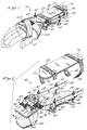
- FIG. 1 is a perspective view of the wrist brace constructed in accordance with a preferred embodiment of the present invention as attached to the arm of a user;
- FIG. 2 is a perspective view illustrating the components comprising the embodiment;
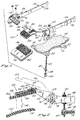
- FIG. 3 is an exploded view illustrating the manner in which the hand brace, anterior forearm plate, and struts of the embodiment are interfaced;
- FIG. 4 is a cross-sectional view taken along line 4-4 of FIG. 2, further illustrating the range of motion of the hand brace;
- FIG. 5 is an exploded view illustrating the manner in which the hand brace is interfaced to a strut;
- FIG. 6 is a perspective view of the palm plate of the embodiment;
- FIG. 7 is a perspective view of a belt member used to maintain the palm plate in abutting contact with the hand brace;
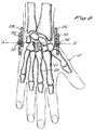
- FIG. 8 is a top view of a user's hand, illustrating the manner in which pivot pins for the hand brace are positioned laterally adjacent the capitate bone of the user's wrist;
- FIG. 9 is a side view of a user's hand, illustrating the bones of the forearm, wrist, and hand in proper alignment;
- FIG. 10 is a side view of a user's hand, illustrating the positions of the bones of the forearm, wrist, and hand wherein a volar transrelocation is required to achieve proper alignment; and
- FIG. 11 is a side view of a user's hand, illustrating the positions of the bones of the forearm, wrist, and hand wherein a dorsal transrelocation is required to achieve proper alignment.
- The description set forth below in connection with appended drawings is intended merely as a description of the functions and structural elements of the invention in connection with the presently preferred embodiment of the invention; it is not intended to represent the only form in which the present invention may be utilized it being understood that the same or equivalent functions and advantages of the present invention may be accomplished by different embodiments encompassed within the scope of the present invention as defined by the appended Claims.
- Referring now to the drawings, the
wrist brace 10 constructed in accordance with the preferred embodiment of the present invention is depicted. For purposes of illustration, thewrist brace 10 is illustrated in a right-arm and hand embodiment which is adapted to be worn upon theright hand 12 of a user. However, it will be recognized that the invention is additionally applicable to left-hand embodiments with the structure of thebrace 10 being the same but reversed in orientation. As best shown in FIGS. 1-3, thewrist brace 10 is composed of ananterior forearm plate 14 and aposterior forearm plate 16. Theanterior forearm plate 14 andposterior forearm plate 16 each have an elongate, generally planar configuration and are positionable on opposite sides of the arm of the user. In this respect, when wearing thebrace 10,anterior plate 14 is positioned adjacent the anterior aspect of the user's forearm whileposterior plate 16 is positioned adjacent the posterior aspect of the user's forearm. In the preferred embodiment,anterior plate 14 andposterior plate 16 are formed from a plastic material having sufficient rigidity to withstand impact forces yet be sufficiently light in weight so as not to overly impair movement of the user's arm. However, other materials possessing sufficient strength and rigidity are contemplated herein. Attached to the inner forearm-contacting surfaces ofanterior plate 14 andposterior plate 16 are layers offoam padding 18 which are used to alleviate discomfort to the user when wearing thewrist brace 10.Posterior plate 16 further includes a generally arcuateproximal extension 20 formed thereon which is preferably positioned above the distal end of the radius of the patient. The attachment ofposterior plate 16 to the user's arm is facilitated by a plurality ofstrap members 22 attached toposterior plate 16, each of which include a "Velcro" (RTM)portion 24 thereon. The manner in whichstrap members 22 are utilized will be explained below. -
Wrist brace 10 of the present invention further includes alateral strut 26 and amedial strut 28.Lateral strut 26 andmedal strut 28 each have an elongate configuration and are positionable on opposite sides of the forearm of a user. Whenbrace 10 is worn by a user,lateral strut 26 is positioned adjacent the lateral aspect of the forearm andmedial strut 28 is positioned adjacent the medial aspect of the forearm. In the preferred embodiment,lateral strut 26 andmedial strut 28 are formed from a plastic material which, likeanterior plate 14 andposterior plate 16, is adapted to possess strength and rigidity yet be light in weight. Additionally, other materials possessing like characteristics are also contemplated herein. Advantageously,lateral strut 26 is formed to include an offset 29 which is adapted to clear the trapezium and scaphoid bones of the user'shand 12 whenbrace 10 is attached thereto. As best seen in FIGS. 2 and 3,lateral strut 26 andmedial strut 28 are attached toanterior forearm plate 14 via a plurality of elongate threadedmembers 30. Each of threadedmembers 30 is preferably formed of plastic and extends through one of the fourelongate grooves 32 laterally disposed withinanterior plate 14. After extending throughgrooves 32, a first pair of threadedmembers 30 are received into and extend through a first set of apertures 34 disposed withinlateral strut 26. Similarly, a second pair of threadedmembers 30 are received into and extend through a second set of apertures 35 disposed withinmedial strut 28. Threadedmembers 30 are secured withingrooves 32 through the utilization oflock washers 38 andnuts 40 which are threadably received onto threadedmembers 30. As will be recognized, the extent to which threadedmembers 30 protrude fromanterior plate 14 is dependent upon the positioning oflock washers 38 andnuts 40 along the length of threadedmembers 30. Additionally, due to the receipt of threadedmembers 30 intoelongate grooves 32, the relative positioning of each of threadedmembers 30 may be adjusted inwardly or outwardly relative the user's forearm. -
Lateral strut 26 andmedial strut 28 are positioned and secured upon threadedmembers 30 through the manipulation of pairs ofknurl nuts 42 which are threadably interfaced to threadedmembers 30. As can be appreciated, by adjusting the positions ofknurl nuts 42 along the length of threadedmembers 30, lateral struts 26 andmedial strut 28 are themselves selectively positionable along the length of threadedmembers 30. Thus, the distance separatinglateral strut 26 frommedial strut 28 may be adjusted by sliding the threadedmembers 30 withingrooves 32, while the distance separatinglateral strut 26 and/ormedial strut 28 fromanterior forearm plate 14 may be adjusted by selectively positioninglateral strut 26 and/ormedial strut 28 on threadedmembers 30. As will be recognized, the aforementioned adjustability oflateral strut 26 andmedial strut 28 is desired to permitwrist brace 10 to be specifically sized in accordance with the anatomical requirements of a particular user. Additionally, the adjustability oflateral strut 26 andmedial strut 28 relativeanterior forearm plate 14 is used to apply downward pressure to the posterior aspect of the user's hand in a manner which will be discussed below. As best seen in FIG. 1,posterior plate 16 is attached toanterior plate 14 by wrapping the opposed ends of each of thestrap members 22 aboutlateral strut 26 andmedial strut 28, respectively, thereby creating a firm interface ofanterior plate 14,posterior plate 16, and struts 26 and 28 to the user's forearm. Thestrap members 22 are maintained in a wrapped orientation aboutlateral strut 26 andmedial strut 28 via thevelcro portions 24 included thereon. - Pivotally connected to the proximal ends of
lateral strut 26 andmedial strut 28 is ahand brace portion 44. Whenbrace 10 is attached to a user's arm,hand brace 44 is positioned adjacent the posterior aspect of the user'shand 12. In the preferred embodiment,hand brace 44 is composed of alateral member 46 and amedial member 48.Lateral member 46 is formed to include alateral extension 50 thereon whilemedial member 48 is formed to include amedial extension 52 thereon.Medial member 48 is preferably slidably connected tolateral member 46 through the receipt of a T-shapedprojection 54 formed onmedial member 48 into a correspondingly shaped recess (not shown) formed withinlateral member 46. Disposed withinprojection 54 ofmedial member 48 are a pair of internally threadedapertures 56 while disposed withinlateral member 46 is anelongate slot 58. As best seen in FIG. 4, whenlateral member 46 is slidably connected tomedial member 48,apertures 56 are coaxially aligned withelongate slot 58. In this respect, the receipt of fasteners, such asscrews 60, intoslot 58 and subsequently intoapertures 56 is operable to rigidly securelateral member 46 tomedial member 48. Additionally, due to the receipt ofscrews 60 intoslot 58, the distance separatinglateral extension 50 frommedial extension 52 may be adjusted so as to coincide with adjustments made to the distance separating struts 26 and 28. - Referring now to FIGS. 3-5, disposed within the proximal end of
medial strut 28 is anaperture 62 and a first pair ofarcuate slots 64. Though not shown, the proximal end oflateral strut 26 includes an aperture and a second pair of arcuate slots disposed therein which are oriented in a configuration identical to that as shown with respect toaperture 62 andarcuate slots 64 ofmedial strut 28. Disposed withinmedial extension 52 is anaperture 66 and a third pair ofarcuate slots 68, while disposed withinlateral extension 50 is an aperture (not shown) and a fourth pair ofarcuate slots 70 which are oriented in a configuration identical toaperture 66 andarcuate slots 68 ofmedial extension 52. In the preferred embodiment,medial member 48 is attached tomedial strut 28 through the receipt of afirst pivot pin 72 into the coaxially alignedapertures lateral member 46 tolateral strut 26 is facilitated by the receipt of asecond pivot pin 74 into the coaxially aligned apertures disposed withinlateral strut 26 andlateral member 46. Whenlateral strut 26 is connected tolateral member 46,arcuate slots 70 are generally aligned with the arcuate slots disposed withinlateral strut 26. Additionally, whenmedial strut 28 is attached tomedial member 48,arcuate slots 64 are generally aligned witharcuate slots 68. - As will be recognized, the pivotal connection between
hand brace 44 and struts 26 and 28 is facilitated byfirst pivot pin 72 andsecond pivot pin 74. As seen in FIG. 8, since thecapitate bone 75 of the wrist serves as the primary pivot point, in order forwrist brace 10 to function properly, it is essential that pivot pins 72 and 74 be positioned on an axis "A" extending laterally throughcapitate bone 75 so as to be disposed laterally on opposite sides of thecapitate bone 75. To verify that such alignment has been achieved, pivot pins 72 and 74 are constructed from a radiopaque material so as to be identifiable in x-ray imaging. As previously indicated, the distance separatinglateral strut 26 frommedial strut 28 may be increased or decreased by adjusting the positions of threadedmembers 30 withinelongate grooves 32 ofanterior plate 14. Becausehand brace 44 is pivotally connected to struts 26 and 28, the distance separatinglateral member 46 frommedial member 48 ofhand brace 44 must be adjusted a distance corresponding to the desired increase or decrease separating struts 26 and 28. As also previously indicated, such adjustment is facilitated by the slidable receipt of T-shapedprojection 54 into the corresponding recess disposed withinlateral member 46. Thus, by looseningscrews 60,lateral member 46 may be moved concurrently withlateral strut 26 andmedial member 48 may be moved concurrently withmedial strut 28. In the preferred embodiment, bothlateral member 46 andmedial member 48 are constructed from plastic, though it will be appreciated that other materials may be utilized as an alternative. - Referring now to FIGS. 4 and 5, the degree of pivotal movement between
hand brace 44 and struts 26 and 28 is controlled by a plurality ofstop members 76. In the preferred embodiment, each ofstop members 76 comprises a fastener, such as ascrew 78, which is initially received into a cylindrical bushing 80 and subsequently into an internally threadedlock member 82. A first pair ofstop members 76 are received into the aligned pairs ofarcuate slots stop members 76 are received into thearcuate slots 70 which are aligned with the arcuate slots disposed within the proximal end oflateral strut 26. When stopmembers 76 are positioned within the respective pairs of aligned slots,hand brace 44 is movable in the manner shown in FIG. 4. As can be appreciated, by adjusting the relative positioning ofstop members 76 within the aligned slot pairs, the movement ofhand brace 44 may be controlled, i.e. limited. In this respect, one stop member comprising each pair may be positioned so as to limit wrist extension while the other stop member comprising the pair may be positioned to limit wrist flexion. - As best seen in FIGS. 3 and 4, attached to the inner, hand-contacting surface of
hand brace 44 is anadaptor pad 84 which is used to provide a firm padded interface betweenhand brace 44 and the posterior aspect of the user's hand.Adaptor pad 84 includes avelcro patch 86 disposed on the outer surface thereof which is used to releasably attachadaptor pad 84 to avelcro patch 88 disposed on the inner surface ofhand brace 44.Adaptor pad 84 further includes a layer ofcushioning material 90 attached to the bottom surface thereof to alleviate any discomfort or irritation to the user'shand 12. - Referring now to FIG. 6, the
wrist brace 10 of the present invention further includes apalm plate 92 which is positioned adjacent the palmar surface of the user's hand. In the preferred embodiment,palm plate 92 includes abracket 94 attached thereto which is used to facilitate the attachment ofpalm plate 92 tohand brace 44 in the manner shown in FIG. 2. In this regard,bracket 94 includes avelcro portion 96 which is releasably attached to avelcro patch 98 disposed on the top surface ofhand brace 44, and more particularlylateral member 46.Palm plate 92 further includes a layer ofcushioning material 100 attached thereto to provide a padded interface betweenpalm plate 92 and the palmar surface of the user's hand. As seen in FIG. 7, abelt member 102 which is constructed from a pliable material is provided to maintainpalm plate 92 in attachment tohand brace 44 and to maintainhand brace 44 in firm contact with the posterior aspect of the user'shand 12.Belt member 102, which includesvelcro patches 104, is interfaced to palmplate 92 andhand brace 44 in the manner shown in FIG. 1. Particularly,belt member 102 extends about thehand 12 of the user with theextension 106 formed thereon extending between the thumb and index finger of the user. - With the structure defined, the operation of the
wrist brace 10 of the present invention may be described. Initially, theanterior forearm plate 14 is positioned adjacent the anterior aspect of the user's forearm and the user'shand 12 is positioned such that thehand brace 44 is positioned adjacent the posterior aspect of thehand 12. Importantly, as such positioning of theanterior forearm plate 14 andhand brace 44 occurs, thestop members 76 are tightened so as to maintainhand brace 44 in a fixed, i.e. "neutral", position which is generally parallel the posterior aspect of the user's hand. Thelateral strut 26 andmedial strut 28 are then adjusted so as to be positioned against the lateral and medial aspects of the user's forearm. Particularly, the distance separating thestruts members 30 within thegrooves 32 disposed withinanterior plate 14. In any instance when the distance separatinglateral strut 26 frommedial strut 28 is being adjusted, thescrews 60 used to rigidly securelateral member 46 tomedial member 48 ofhand brace 44 are loosened so as to permit thelateral member 46 andmedial member 48 to slide relative to one another a distance coinciding with the distance adjustments being made between thestruts members 30 in the proper orientation and thescrews 60 are tightened to maintain thelateral member 46 andmedial member 48 in the proper orientation. Additionally, the distance separating thestruts anterior plate 14 is adjusted by looseningknurl nuts 42 and positioning thestruts members 30 so as to be substantially centered between the anterior and posterior aspects of the user's arm. - After the
anterior plate 14 and struts 26 and 28 have been positioned on the user's forearm, theposterior forearm plate 16 is attached to thestruts wrist brace 10 on the user's forearm. Particularly, thestrap members 22 are wrapped aboutstruts velcro portions 24 contained thereon.Posterior plate 16 is oriented such that thearcuate extension 20 formed thereon is positioned above the distal end of the radius of the user. Oncewrist brace 10 has been secured to the user's forearm, thehand brace 44 is caused to apply downward pressure to the secondmetacarpal bone 21 and thirdmetacarpal bone 23 of the user's hand 12 (shown in FIG. 8). In the preferred embodiment, the application of such pressure is facilitated by movinglateral strut 26 andmedial strut 28 downwardly along the length of threadedmembers 30 towardanterior plate 14. As previously specified,hand brace 44 is initially fixed in a neutral position. Thus, by movinglateral strut 26 andmedial strut 28 towardanterior plate 14,hand brace 44 is abutted against the posterior aspect of the user's hand in a manner operable to apply the aforementioned downward pressure. Such downward pressure is necessary for purposes of causing a volar transrelocation to correct a malalignment of the bones of the user's hand, wrist, and forearm, as seen in FIG. 16. - When
anterior plate 14 and struts 26 and 28 are properly positioned about the forearm of the user, thefirst pivot pin 72 andsecond pivot pin 74 will preferably be disposed on opposite sides of thecapitate bone 75 of the wrist of the user. As previously indicated, thefirst pivot pin 72 andsecond pivot pin 74 are constructed of a radiopaque material so as to be identifiable in an x-ray. As such, to insure that pivot pins 72 and 74 are properly positioned adjacent thecapitate bone 75, an x-ray of the user's hand is taken to insure that the proper positioning of pivot pins 72 and 74 has been achieved. If thepins anterior plate 14 and struts 26 and 28 are repositioned on the forearm of the user and another x-ray taken to check the positioning of the pivot pins 72 and 74. This particular process is repeated until the proper orientation of the pivot pins 72 and 74 has been obtained. The x-ray is also used to determine whether the downward pressure exerted by thehand brace 44 is properly aligning the bones of the user's hand, wrist, and forearm in the manner shown in FIG. 15. As such, if a determination is made that proper alignment has not been obtained, the pressure exerted by thehand brace 44 is adjusted via the repositioning of thelateral strut 26 andmedial strut 28 relative the threadedmembers 30. Additionally, in those instances where due to the small size of the user's hand, insufficient downward pressure is applied by thehand brace 44 though thestruts adapter pad 84 to exert the necessary pressure. - After the
anterior forearm plate 14 and struts 26 and 28 have been properly positioned and proper bone alignment has been achieved, thepalm plate 92 is attached to thehand brace 44 by securing thevelcro patch 96 ofbracket 94 to thevelcro patch 98 disposed on the outer surface oflateral member 46.Palm plate 92 is attached tohand brace 44 in a manner wherein thecushioning material 100 included thereon is in firm contact with the palmar surface of the user's hand. Afterpalm plate 92 has been properly positioned,belt member 102 is wrapped about thehand 12 of the user with theextension 106 ofbelt member 102 being disposed between the thumb and index finger of the user'shand 12.Belt member 102 is maintained in its proper position through the use of thevelcro patches 104 contained thereon. - The downward pressure exerted on the second and third metacarpals by the
hand brace 44 causes a volar transrelocation as needed to correct a malalignment of the hand or the forearm due to a fracture of the distal radius (i.e. a Colles' fracture), an intercalary carpal instability, or a sub-luxation due to wrist ligament injury. Because the pressure against the metacarpals is constantly maintained, the wrist may be slightly pivoted or rotated without causing further injury to or inhibiting the healing of one of the aforementioned injuries. Indeed, as previously specified, allowing slight movement of the wrist during the healing process aids the healing process. In the initial stages of the healing process, thestop members 76 are positioned in a manner so as to not allow any pivotal movement of the wrist of the user. As the healing process progresses, the positions stopmembers 76 may be adjusted so as to permit increasing degrees of flexion and/or extension of the wrist of the user. The use ofbelt member 102 maintains theadaptor pad 84 ofhand brace 44 and thecushioning material 100 ofpalm plate 92 in firm contact with thehand 12 of the user. - In the foregoing, references have been made to a volar transrelocation of the user's wrist as caused by the downward pressure exerted by the
hand brace 44 on the posterior aspect of the user'shand 12, and more particularly, the secondmetacarpal bone 21 and thirdmetacarpal bone 23. FIG. 9 illustrates thecapitate bone 75 and secondmetacarpal bone 21 of the user'shand 12 in proper alignment. As illustrated in FIG. 10, when thecapitate bone 75 and metacarpal bones are forced into an orientation above that which is normal due to a particular wrist injury, a volar transrelocation is needed to push the bones into a normal alignment. As will be recognized, due to the nature of the bone malalignment as shown in FIG. 10, a volar transrelocation requires that a downward pressure be exerted upon the posterior aspect of the user's hand to achieve proper alignment. As such, thehand brace 44 is adapted to exert such downward pressure. Referring now to FIG. 11, certain wrist injuries cause thecapitate bone 75 and metacarpal bones to achieve an orientation below that which is normal. In this particular situation, a dorsal transrelocation is needed to push the wrist bones into a normal alignment. Due to the nature of the bone malalignment shown in FIG. 11, a dorsal transrelocation is facilitated by exerting upward pressure against the palmar surface of the user'shand 12 to achieve a proper alignment.
Claims (14)
- A wrist brace (10) comprising a forearm support (14, 16), a lateral strut (26) attached to said forearm support so as to be positioned adjacent the lateral aspect of the forearm; a medial strut (29) attached to said forearm support so as to be positioned adjacent the medial aspect of the forearm, and a hand brace (44) pivotally connected (50, 52; 62, 64; 66, 68; 70; 72, 74) to the proximal ends of said lateral and medal struts and positionable by said lateral and medial struts adjacent the posterior aspect of a user's hand (12), characterised in that,said forearm support comprises an anterior forearm plate (14) positionable adjacent the anterior aspect of a user's forearm and a posterior forearm plate (16) positionable adjacent the posterior forearm aspect of the user's forearm and releasably attachable to said lateral and medal struts,in that said hand brace is adapted to selectively apply downward pressure to the second and third metacarpal bones of the user's hand;and in that the pivotal connection of said hand brace to said lateral and medal struts is adapted to permit controlled pivotal movement of a user's wrist about a single axis.
- A brace according to Claim 1 characterised in that said lateral strut (26) includes an offset (29) formed therein adapted to clear the trapezium and scaphoid bones of the user's wrist.
- A brace according to Claim l or 2, characterised by means (30, 32, 42) associated with said lateral and media struts (26, 28) for adjusting the distance separating said lateral strut from said medial strut and the distance separating these struts from said anterior forearm plate, said adjusting means being operable to properly align the struts relative the lateral and medal aspects of the forearm and cause the hand brace (44) to apply downward pressure to the posterior aspect of the user's hand (12).
- A brace according to Claim 3, characterised in that said adjusting means comprises;a first pair of elongate threaded members (30) extending through and interconnecting said anterior forearm plate (14) and said lateral strut (26); anda second pair of elongate threaded members (30) extending through and interconnecting said anterior forearm plate (14) and said medal strut;said lateral strut being selectively positionable along the length of said first pair of threaded members and said medial strut being selectively positionable along the length of said second pair of threaded members.
- A brace according to Claim 4, characterised in that said first pair of threaded members (30) extend through a first pair of elongate grooves (32) disposed within said anterior forearm plate and said second pair of threaded members extend through a second pair of elongate grooves (32) disposed within said anterior forearm plate, said first and second pairs of grooves being adapted to permit the positions of said first and second pairs of threaded members (30) to be adjusted inwardly and outwardly relative the forearm.
- A brace according to Claim 3, 4, or 5, characterised in that said hand brace (44) comprises:a lateral member (46) having a lateral extension (50) formed thereon which includes a first pair of arcuate slots (64) disposed therein; anda media member (58) slidably connected to said lateral member and having a medal extension (52) formed thereon which includes a second pair of arcuate slots disposed therein, the slidable connection (54) being operable to allow the distance separating said lateral extension and said medial extension to be adjusted.
- A brace according to Claim 6, characterised in that said lateral strut (26) includes a third pair of arcuate slots (68) disposed within the proximal end thereof and said medal strut (28) includes a fourth pair of arcuate slots (70) disposed within the proximal end thereof, said third and fourth pairs of slots being oriented such that, when said hand brace (44) is pivotally connected to said struts, said first and third pairs of slots and said second and fourth pairs of slots are in general alignment.
- A brace according to Claim 7, characterised in that the pivotal connection between said hand brace (44) and said lateral and media struts (26, 28) is facilitated by a first pivot pin (72) used to connect said lateral extension (50) to the proximal end of said lateral strut and a second pivot pin (74) used to connect said medial extension (52) to said proximal end of said medal strut, said wrist brace (10) being attachable to the arm of the user such that said pivot pins can be disposed laterally on opposite sides of the capitate bone of the user's wrist.
- A brace according to Claim 8, characterised in that said first and second pins (72, 74) are constructed of a radiopaque material whereby said pins are identifiable in an x-ray.
- A brace according to Claim 8, or 9, characterised by a first pair of stop members (76) extending through said first and third pairs of aligned slots and a second pair of said stop members (76) extending through said second and fourth pairs of aligned slots, said first and second pairs of stop members being operable to control the amount of flexion and extension of said hand brace (44) relative said lateral and medial struts (26, 28).
- A brace according to any one of the preceding Claims, characterised by a palm plate (92) releasably attached to said hand brace (44) in a manner wherein said palm plate is positionable adjacent the palmar surface of the user's hand.
- A brace according to Claim 11, characterised by a belt member (102) usable to maintain the palm plate in abutting contact with the palmar surface of the user's hand.
- A brace according to any one of the preceding Claims, characterised in that said posterior forearm plate (16) includes at least one strap member (22) attached thereto to facilitate the attachment of said posterior forearm plate to said lateral and medial struts (26, 28).
- A brace according to any one of the preceding Claims, characterised in that at least one adapter pad (84) is releasably attached to said hand brace (44) for providing a padded interface between said hand brace and the posterior aspect of the user's hand.
Priority Applications (2)
| Application Number | Priority Date | Filing Date | Title |
|---|---|---|---|
| DE69217922T DE69217922D1 (en) | 1992-06-19 | 1992-06-19 | Wrist orthosis |
| AT92305639T ATE149330T1 (en) | 1992-06-19 | 1992-06-19 | WRIST BORTHESIS |
Applications Claiming Priority (1)
| Application Number | Priority Date | Filing Date | Title |
|---|---|---|---|
| US07/710,359 US5203766A (en) | 1991-06-03 | 1991-06-03 | Wrist brace |
Publications (2)
| Publication Number | Publication Date |
|---|---|
| EP0574627A1 EP0574627A1 (en) | 1993-12-22 |
| EP0574627B1 true EP0574627B1 (en) | 1997-03-05 |
Family
ID=24853712
Family Applications (1)
| Application Number | Title | Priority Date | Filing Date |
|---|---|---|---|
| EP92305639A Expired - Lifetime EP0574627B1 (en) | 1991-06-03 | 1992-06-19 | Wrist brace |
Country Status (2)
| Country | Link |
|---|---|
| US (1) | US5203766A (en) |
| EP (1) | EP0574627B1 (en) |
Families Citing this family (23)
| Publication number | Priority date | Publication date | Assignee | Title |
|---|---|---|---|---|
| US5372145A (en) * | 1992-09-16 | 1994-12-13 | Berger; J. Lee | Surgical hand support apparatus |
| US6125852A (en) * | 1993-02-22 | 2000-10-03 | Heartport, Inc. | Minimally-invasive devices and methods for treatment of congestive heart failure |
| US5759165A (en) * | 1993-06-30 | 1998-06-02 | Empi, Inc. | Forearm supination range-of-motion orthosis |
| GB9411445D0 (en) * | 1994-06-08 | 1994-07-27 | Univ Brunel | A splint |
| US5547463A (en) * | 1994-10-07 | 1996-08-20 | United States Surgical Corporation | Surgical hand support apparatus |
| US5865783A (en) * | 1996-05-03 | 1999-02-02 | Klimoski; David B. | Physiology based wrist support |
| US5722092A (en) * | 1996-11-19 | 1998-03-03 | Borzecki; Mark | Protective arm and wrist guard |
| US6129690A (en) * | 1998-07-29 | 2000-10-10 | Empi Corp. | Unidirectional resistance pivot assembly for a splint |
| US6328706B1 (en) * | 2000-05-01 | 2001-12-11 | Khamkong Yattavong | Wrist support device |
| GB0205383D0 (en) * | 2002-03-07 | 2002-04-24 | Grampian Univ Hospitals | Orthopaedic brace |
| CN100355407C (en) * | 2004-03-05 | 2007-12-19 | 香港理工大学 | Carpal Fracture Reduction and Fixation Devices |
| US6988998B1 (en) * | 2005-01-18 | 2006-01-24 | Horacio Santaana-Dela Rosa | Dynamic dorsal-blocking adjustable splint |
| RU2307626C1 (en) * | 2005-12-02 | 2007-10-10 | ФГУ Центральный научно-исследовательский Институт травматологии и ортопедии им. Н.Н. Приорова Росздрава | Functional bus for rehabilitation of patients with damaged radial nerve |
| US8070702B2 (en) | 2007-10-11 | 2011-12-06 | Saebo, Inc. | Splint assembly for positioning of the hand |
| US8905950B2 (en) * | 2008-03-04 | 2014-12-09 | Bonutti Research, Inc. | Shoulder ROM orthosis |
| US8157664B2 (en) | 2008-12-05 | 2012-04-17 | Even Par Enterprises, Inc. | Assist device |
| USD663798S1 (en) * | 2009-07-01 | 2012-07-17 | Even Par Enterprises, Inc. | Assist device |
| US8312563B1 (en) * | 2010-04-07 | 2012-11-20 | Walter Burns | Protective glove with thumb and wrist support |
| IN2013CH04450A (en) * | 2013-09-30 | 2015-04-03 | Dhama Innovations Private Ltd | |
| CH712867A1 (en) * | 2016-08-30 | 2018-03-15 | Medivation Ag | Portable immobilization and fixation device with calibration unit for x-ray stereomicrographs. |
| CN110769788A (en) * | 2017-06-15 | 2020-02-07 | 普兰什·库玛 | Systems and components for the treatment of fractures |
| RU191046U1 (en) * | 2019-01-15 | 2019-07-22 | Ольга Геннадьевна Шершнева | An orthosis for the rehabilitation of patients with isolated and combined injuries of the scaphoid-lunate ligament of the wrist joint |
| RU2762482C1 (en) * | 2021-03-29 | 2021-12-21 | Ростислав Андреевич Тюрин | Device for rehabilitation of patients with radial nerve damage |
Family Cites Families (9)
| Publication number | Priority date | Publication date | Assignee | Title |
|---|---|---|---|---|
| GB104295A (en) * | 1916-07-25 | 1917-03-01 | Douglas Ormerod Murton | An Improved Surgical Wrist-splint. |
| US2438144A (en) * | 1945-07-06 | 1948-03-23 | Jr Benn A Bunyar | Surgical brace |
| US3707963A (en) * | 1970-01-21 | 1973-01-02 | M Keropian | Articulated hand brace |
| US4384571A (en) * | 1981-12-24 | 1983-05-24 | Jung Corporation | Adjustable digital/metacarpal splint |
| US4538600A (en) * | 1983-10-27 | 1985-09-03 | Dynasplint Systems, Inc. | Adjustable splint |
| US4618147A (en) * | 1985-07-02 | 1986-10-21 | Accuswing, Incorporated | Bowling glove |
| US4660550A (en) * | 1985-07-26 | 1987-04-28 | Bodine Rudolph H | Articulated hand splint with multiple pivot points |
| US4809688A (en) * | 1986-04-22 | 1989-03-07 | Empresa Cubana Importadora Y. Exportadora Of Products Medicos, T/A Medicuba | Sinergic splint for early mobilization of the flexor tendons of the hand |
| US5002044A (en) * | 1989-10-10 | 1991-03-26 | Carter Peter R | Derotation wrist brace |
-
1991
- 1991-06-03 US US07/710,359 patent/US5203766A/en not_active Expired - Fee Related
-
1992
- 1992-06-19 EP EP92305639A patent/EP0574627B1/en not_active Expired - Lifetime
Also Published As
| Publication number | Publication date |
|---|---|
| US5203766A (en) | 1993-04-20 |
| EP0574627A1 (en) | 1993-12-22 |
Similar Documents
| Publication | Publication Date | Title |
|---|---|---|
| US5254078A (en) | Wrist brace | |
| US5203766A (en) | Wrist brace | |
| US5662594A (en) | Dynamic exoskeletal orthosis | |
| US4873967A (en) | Knee orthosis | |
| US4643177A (en) | Dynamic traction wrist cast brace | |
| US5358469A (en) | Dynamic splint | |
| EP0900066B1 (en) | Angular compensation device for a joint brace | |
| US5658241A (en) | Multi-functional dynamic splint | |
| EP0737455B1 (en) | Abduction splint for the shoulder and arm | |
| US5759165A (en) | Forearm supination range-of-motion orthosis | |
| US4275716A (en) | Knee brace | |
| US6171309B1 (en) | External fixator for repairing fractures of distal radius and wrist | |
| US5545162A (en) | External fixator for repairing fractures of distal radius and wrist | |
| US4719906A (en) | Universal articulated splint | |
| US3707963A (en) | Articulated hand brace | |
| US6293918B1 (en) | Adjustable splint | |
| US7037286B1 (en) | Wrist brace | |
| US4945902A (en) | Progressive static flexion device for phalanges | |
| US4715363A (en) | Knee brace with extension angle establishing means | |
| US4915098A (en) | Orthopaedic hinge mechanism | |
| GB2184659A (en) | Adjustable wrist splint | |
| US9259344B2 (en) | Pronation/supination orthosis and method | |
| EP0277663B1 (en) | Adjustable splint | |
| JPH0326251A (en) | Action control mechanism for orthopedic sup- porter | |
| WO1990001308A1 (en) | Adjustable splint |
Legal Events
| Date | Code | Title | Description |
|---|---|---|---|
| PUAI | Public reference made under article 153(3) epc to a published international application that has entered the european phase |
Free format text: ORIGINAL CODE: 0009012 |
|
| AK | Designated contracting states |
Kind code of ref document: A1 Designated state(s): AT BE CH DE DK ES FR GB GR IT LI LU MC NL PT SE |
|
| 17P | Request for examination filed |
Effective date: 19940606 |
|
| 17Q | First examination report despatched |
Effective date: 19950906 |
|
| GRAG | Despatch of communication of intention to grant |
Free format text: ORIGINAL CODE: EPIDOS AGRA |
|
| GRAH | Despatch of communication of intention to grant a patent |
Free format text: ORIGINAL CODE: EPIDOS IGRA |
|
| GRAH | Despatch of communication of intention to grant a patent |
Free format text: ORIGINAL CODE: EPIDOS IGRA |
|
| GRAA | (expected) grant |
Free format text: ORIGINAL CODE: 0009210 |
|
| AK | Designated contracting states |
Kind code of ref document: B1 Designated state(s): AT BE CH DE DK ES FR GB GR IT LI LU MC NL PT SE |
|
| PG25 | Lapsed in a contracting state [announced via postgrant information from national office to epo] |
Ref country code: NL Free format text: LAPSE BECAUSE OF FAILURE TO SUBMIT A TRANSLATION OF THE DESCRIPTION OR TO PAY THE FEE WITHIN THE PRESCRIBED TIME-LIMIT Effective date: 19970305 Ref country code: LI Effective date: 19970305 Ref country code: IT Free format text: LAPSE BECAUSE OF FAILURE TO SUBMIT A TRANSLATION OF THE DESCRIPTION OR TO PAY THE FEE WITHIN THE PRE;WARNING: LAPSES OF ITALIAN PATENTS WITH EFFECTIVE DATE BEFORE 2007 MAY HAVE OCCURRED AT ANY TIME BEFORE 2007. THE CORRECT EFFECTIVE DATE MAY BE DIFFERENT FROM THE ONE RECORDED.SCRIBED TIME-LIMIT Effective date: 19970305 Ref country code: GR Free format text: LAPSE BECAUSE OF FAILURE TO SUBMIT A TRANSLATION OF THE DESCRIPTION OR TO PAY THE FEE WITHIN THE PRESCRIBED TIME-LIMIT Effective date: 19970305 Ref country code: FR Effective date: 19970305 Ref country code: ES Free format text: THE PATENT HAS BEEN ANNULLED BY A DECISION OF A NATIONAL AUTHORITY Effective date: 19970305 Ref country code: DK Effective date: 19970305 Ref country code: CH Effective date: 19970305 Ref country code: BE Effective date: 19970305 Ref country code: AT Effective date: 19970305 |
|
| REF | Corresponds to: |
Ref document number: 149330 Country of ref document: AT Date of ref document: 19970315 Kind code of ref document: T |
|
| REG | Reference to a national code |
Ref country code: CH Ref legal event code: EP |
|
| REF | Corresponds to: |
Ref document number: 69217922 Country of ref document: DE Date of ref document: 19970410 |
|
| PG25 | Lapsed in a contracting state [announced via postgrant information from national office to epo] |
Ref country code: SE Effective date: 19970605 Ref country code: PT Effective date: 19970605 |
|
| PG25 | Lapsed in a contracting state [announced via postgrant information from national office to epo] |
Ref country code: DE Effective date: 19970606 |
|
| PG25 | Lapsed in a contracting state [announced via postgrant information from national office to epo] |
Ref country code: LU Free format text: LAPSE BECAUSE OF NON-PAYMENT OF DUE FEES Effective date: 19970619 Ref country code: GB Free format text: LAPSE BECAUSE OF NON-PAYMENT OF DUE FEES Effective date: 19970619 |
|
| EN | Fr: translation not filed | ||
| NLV1 | Nl: lapsed or annulled due to failure to fulfill the requirements of art. 29p and 29m of the patents act | ||
| REG | Reference to a national code |
Ref country code: CH Ref legal event code: PL |
|
| PG25 | Lapsed in a contracting state [announced via postgrant information from national office to epo] |
Ref country code: MC Effective date: 19971231 |
|
| PLBE | No opposition filed within time limit |
Free format text: ORIGINAL CODE: 0009261 |
|
| STAA | Information on the status of an ep patent application or granted ep patent |
Free format text: STATUS: NO OPPOSITION FILED WITHIN TIME LIMIT |
|
| GBPC | Gb: european patent ceased through non-payment of renewal fee |
Effective date: 19970619 |
|
| 26N | No opposition filed |