EP0574428B1 - Mounting device for armrests - Google Patents
Mounting device for armrests Download PDFInfo
- Publication number
- EP0574428B1 EP0574428B1 EP92904924A EP92904924A EP0574428B1 EP 0574428 B1 EP0574428 B1 EP 0574428B1 EP 92904924 A EP92904924 A EP 92904924A EP 92904924 A EP92904924 A EP 92904924A EP 0574428 B1 EP0574428 B1 EP 0574428B1
- Authority
- EP
- European Patent Office
- Prior art keywords
- attachment
- armrest
- ridges
- armrests
- circular part
- Prior art date
- Legal status (The legal status is an assumption and is not a legal conclusion. Google has not performed a legal analysis and makes no representation as to the accuracy of the status listed.)
- Expired - Lifetime
Links
Images
Classifications
-
- A—HUMAN NECESSITIES
- A47—FURNITURE; DOMESTIC ARTICLES OR APPLIANCES; COFFEE MILLS; SPICE MILLS; SUCTION CLEANERS IN GENERAL
- A47K—SANITARY EQUIPMENT; ACCESSORIES THEREFOR, e.g. TOILET ACCESSORIES
- A47K17/00—Other sanitary equipment not covered by the other groups of this subclass ; Holders for toilet brushes
- A47K17/02—Body supports, other than seats, for closets, e.g. handles, back-rests, foot-rests; Accessories for closets, e.g. reading tables
- A47K17/026—Armrests mounted on or around the toilet
-
- A—HUMAN NECESSITIES
- A47—FURNITURE; DOMESTIC ARTICLES OR APPLIANCES; COFFEE MILLS; SPICE MILLS; SUCTION CLEANERS IN GENERAL
- A47C—CHAIRS; SOFAS; BEDS
- A47C7/00—Parts, details, or accessories of chairs or stools
- A47C7/54—Supports for the arms
- A47C7/543—Supports for the arms movable to inoperative position
Definitions
- the present invention relates to an arrangement for the attachment of armrests, and more particularly, although not exclusively, to an arrangement which will enable armrests to be pivoted to a limited extent.
- the invention can be applied to many different designs of armrests, it is primarily intended for use with chairs, lavatory basins and the like that are meant for handicapped people.
- Armrests mounted on chairs and like seating furniture intended for handicapped people can normally be swung between a generally horizontal position, which is the normal arm-resting position, and a generally vertical position, which will enable a person to seat himself/herself on the chair from one side thereof.
- This latter, vertical arm position is essential when a handicapped person moves from a wheelchair to a conventional chair, which is often accomplished by moving sideways.
- the object of the present invention is to solve the aforesaid problem. This object is achieved by an arrangement of the kind defined in the claims, which also set forth the special characteristic features of the invention.
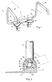
- the armrest arrangement 1 illustrated in Figure 1 is intended for a lavatory basin or or toilet bowl and is comprised of an attachment 2 and two armrests 3 and 4 which are pivotally connected individually to the attachment 2.
- Projecting from the underside of the attachment 2 is a pair of screws S, each being provided with a respective nut 6 at the bottom thereof.
- These screws 5 are intended to be inserted through corresponding holes in the lavatory basin, in that part thereof which is located between the water tank and the actual basin or bowl, i.e. in the manner conventional when fitting a toilet seat and toilet seat-cover to the basin, the nuts 6 functioning to securely lock the attachment 2.
- the attachment 2 has a relatively elongated configuration and the armrests 3, 4 project out from respective short ends of the attachment.
- the attachment 2 is also provided with two pairs of lugs 7, 8 which project out towards the lavatory basin when the attachment 2 is in position, and which is intended for the pivotal attachment of a lavatory seat, and optionally also a seat cover.
- the attachment 2 is also provided with a pair of disc-like projections 9, 10 which are intended to rest on the rim of the lavatory basin and therewith form a support for the attachment 2 against the breaking forces to which the attachment is subjected when a load is exerted on the armrests 3, 4.
- the attachment 2 comprises two parts, an upper part 12 on which the aforesaid pairs of lugs 7, 8 are disposed, and a lower part 11 which is intended to rest against the lavatory basin and which is provided with both the projections 9, 10 and the fastener screws 5.
- the two armrests 3, 4 are made of round tubing and are a mirror image of one another and include a straight part 13 which extends from within the attachment 2 and terminates a short distance therefrom, a substantially vertical part 14, and a substantially horizontal part 15 which extends forwardly, at the side of the person seated on the lavatory basin.
- the horizontal part 15 is upholstered in some way or another, so as to feel comfortable to the person resting his/her arms on the armrests. It will be understood, however, that the armrests may have different configurations to that just described, the described configuration simply being one of a number of possible configurations.
- Figure 2 illustrates the manner in which an armrest, in this case the armrest 3 shown in Figure 1, is attached to the attachment 2 in a manner which restricts the extent to which the armrest 3 can pivot between two extreme positions, one in which the armrest 3 is in its horizontal position of use, shown in full lines, and one position in which the armrest 3 is swung back to a position in which it does not cause an obstruction, as shown in broken lines.
- That part of the armrest part 13 which is located within the attachment 2 has been subjected to a pressing operation at two diametrically opposed regions 16, 17, to form hollows or sunken, these regions being mutually separated by two ridges 18, 19 located diametrically opposite one another.
- the tubular part 13 retains its original shape and size axially on either side of the depressed regions or hollows 16, 17.
- an element 20 which, when seen from above, has a generally rectangular shape with two upwardly-projecting ridges 21, 22, one on each long side of the element 20 and thus parallel with the armrest part 13.
- the length of the ridges 21, 22 is practically the same as the length of the depressed regions 16, 17 and projects in to one, 16, of said regions.
- ridges 23, 24 which lie generally opposite the ridges 21, 22 in the lower part of said attachment, these ridges projecting in to the other depressed region 17.
- the positions of the ridges 18, 19 on the armrest part 13 is such in relation to the armrest 3 and to the ridges 21-24 in respective attachment parts 11, 12 as to enable the armrest 3 to be swung solely between said two extreme positions.
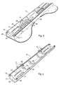
- FIG. 3 illustrates the construction of the lower or bottom part 11 of the attachment 2.
- This lower part comprises, in principle, a wall 25 which defines in part a rectangular area and against which the upper part 12 of the attachment 2 is intended to rest.
- a semi-circular recess 27 Formed in respective short sides 26 of said lower attachment part is a semi-circular recess 27 whose radius corresponds to or is somewhat larger than the radius of the armrest part 13 and thus forms part of a journal bearing for said armrest part.
- the element 20 Located slightly inwards of the short side 26 is the element 20 provided with ridges 21, 22.
- the element 20 has essentially a box-like shape. Slightly inwards of the element 20 is an inner transverse wall 28 which also has a semi-circular recess corresponding to the earlier mentioned recess 27.
- An elongated, penetrating hole 29 extends from the element 20 to a further transverse wall 30 which is located somewhat inwardly of the transverse wall 28 and which is also provided with a semi-circular recess corresponding to the aforesaid recesses.
- the hole 29 is intended to receive an attachment screw 5 by means of which said hole can be moved to locations at different distances between the attachment holes provided in the lavatory basin.
- the lower part 11 of the attachment 2 is also provided with penetrating holes 31 in the vicinity of the end walls and transverse walls, for securing said parts with the aid of screws.
- Figure 4 illustrates the construction of the upper attachment part 12.
- the outer shape of the upper attachment part 12 corresponds to the shape presented by the wall 25 on the lower attachment part 11.
- the end walls 32 are provided with semi-circular recesses 33 of the same radius as the radius of the corresponding recess 27 in the lower attachment part 11, while transverse walls 34, 35 provided with semi-circular recesses are located in positions which register with corresponding transverse walls 28, 30 in the lower attachment part.
- the earlier mentioned ridges 23, 24 are located between the end walls 32 and the transverse walls 34.
- Provided adjacent the end walls and transverse walls are blind, threaded holes 36 into which screws are screwed when the attachment 2 is assembled, these screws extending through the holes 31 provided in the lower attachment part 11.
- the armrests 3, 4 may have any design whatsoever within the scope of the present invention, with the exception of the armrest part 13 which must coact with the attachment 2 in order to allow the armrest to swing to said limited extent between these extreme positions.
- the attachment may have different configurations, to suit different usages, and that the invention is therefore not restricted to use only with lavatory basins.
- the essential feature in this respect is that the component parts of the arrangement are simple and reliable and afford an inexpensive and satisfactory solution to the problems recited in the introduction and solved by means of the present invention.
Landscapes
- Health & Medical Sciences (AREA)
- Public Health (AREA)
- Epidemiology (AREA)
- General Health & Medical Sciences (AREA)
- Chair Legs, Seat Parts, And Backrests (AREA)
- Toilet Supplies (AREA)
- Passenger Equipment (AREA)
- Clamps And Clips (AREA)
- Cylinder Crankcases Of Internal Combustion Engines (AREA)
- Medicines Containing Material From Animals Or Micro-Organisms (AREA)
Abstract
Description
- The present invention relates to an arrangement for the attachment of armrests, and more particularly, although not exclusively, to an arrangement which will enable armrests to be pivoted to a limited extent. Although the invention can be applied to many different designs of armrests, it is primarily intended for use with chairs, lavatory basins and the like that are meant for handicapped people.
- Armrests mounted on chairs and like seating furniture intended for handicapped people can normally be swung between a generally horizontal position, which is the normal arm-resting position, and a generally vertical position, which will enable a person to seat himself/herself on the chair from one side thereof. This latter, vertical arm position is essential when a handicapped person moves from a wheelchair to a conventional chair, which is often accomplished by moving sideways.
- Many solutions are known to the art for pivotally mounting armrests to chairs and like furniture. These solutions include various types of stop pins and grooves which limit pivotal movement of the armrest. These known solutions, however, are encumbered with certain drawbacks. For example, in the case of the more simple designs, which are relatively common in practice, the person seated in the chair, the clothing worn by said person, is liable be clamped or pinched between the pin and the groove. More expensive constructions include the provision of separate guards. The pins and grooves also require separate machining processes and fitting processes, and since equipment of the kind to which the present invention relates include plastic-coated tubing in the majority of cases, it is difficult to retain the plastic material on the wear surfaces around the pins. Those areas from which the plastic has loosened are liable to become rusty, resulting in loosening of the plastic over progressively larger areas.
- The object of the present invention is to solve the aforesaid problem. This object is achieved by an arrangement of the kind defined in the claims, which also set forth the special characteristic features of the invention.
- The invention will now be described in more detail with reference to the accompanying drawings, in which
- FIGURE 1
- is a perspective view of an inventive armrest arrangement intended to be fitted to a lavatory basin;
- FIGURE 2
- is a sectional view of the actual attachment for a pivotal armrest;
- FIGURE 3
- is a perspective top view of one of the two elements which hold the pivotal armrest secured to a lavatory basin; and
- FIGURE 4
- is a perspective view from beneath of the other element which holds the pivotal armrest secured to a lavatory basin.
- The
armrest arrangement 1 illustrated in Figure 1 is intended for a lavatory basin or or toilet bowl and is comprised of anattachment 2 and twoarmrests 3 and 4 which are pivotally connected individually to theattachment 2. Projecting from the underside of theattachment 2 is a pair of screws S, each being provided with arespective nut 6 at the bottom thereof. Thesescrews 5 are intended to be inserted through corresponding holes in the lavatory basin, in that part thereof which is located between the water tank and the actual basin or bowl, i.e. in the manner conventional when fitting a toilet seat and toilet seat-cover to the basin, thenuts 6 functioning to securely lock theattachment 2. As will be seen from Figure 1, theattachment 2 has a relatively elongated configuration and thearmrests 3, 4 project out from respective short ends of the attachment. Theattachment 2 is also provided with two pairs oflugs attachment 2 is in position, and which is intended for the pivotal attachment of a lavatory seat, and optionally also a seat cover. In the case of the illustrated embodiment, theattachment 2 is also provided with a pair of disc-like projections attachment 2 against the breaking forces to which the attachment is subjected when a load is exerted on thearmrests 3, 4. - The
attachment 2 comprises two parts, anupper part 12 on which the aforesaid pairs oflugs lower part 11 which is intended to rest against the lavatory basin and which is provided with both theprojections fastener screws 5. - The two
armrests 3, 4 are made of round tubing and are a mirror image of one another and include astraight part 13 which extends from within theattachment 2 and terminates a short distance therefrom, a substantiallyvertical part 14, and a substantiallyhorizontal part 15 which extends forwardly, at the side of the person seated on the lavatory basin. Thehorizontal part 15 is upholstered in some way or another, so as to feel comfortable to the person resting his/her arms on the armrests. It will be understood, however, that the armrests may have different configurations to that just described, the described configuration simply being one of a number of possible configurations. - Figure 2 illustrates the manner in which an armrest, in this case the
armrest 3 shown in Figure 1, is attached to theattachment 2 in a manner which restricts the extent to which thearmrest 3 can pivot between two extreme positions, one in which thearmrest 3 is in its horizontal position of use, shown in full lines, and one position in which thearmrest 3 is swung back to a position in which it does not cause an obstruction, as shown in broken lines. That part of thearmrest part 13 which is located within theattachment 2 has been subjected to a pressing operation at two diametricallyopposed regions ridges tubular part 13 retains its original shape and size axially on either side of the depressed regions orhollows - Provided in the
lower part 11 of theattachment 2 is anelement 20 which, when seen from above, has a generally rectangular shape with two upwardly-projectingridges element 20 and thus parallel with thearmrest part 13. The length of theridges depressed regions - Located in the
upper part 12 of theattachment 2 is a pair ofridges ridges depressed region 17. The positions of theridges armrest part 13 is such in relation to thearmrest 3 and to the ridges 21-24 inrespective attachment parts armrest 3 to be swung solely between said two extreme positions. - Figure 3 illustrates the construction of the lower or
bottom part 11 of theattachment 2. This lower part comprises, in principle, awall 25 which defines in part a rectangular area and against which theupper part 12 of theattachment 2 is intended to rest. Formed in respectiveshort sides 26 of said lower attachment part is asemi-circular recess 27 whose radius corresponds to or is somewhat larger than the radius of thearmrest part 13 and thus forms part of a journal bearing for said armrest part. Located slightly inwards of theshort side 26 is theelement 20 provided withridges element 20 has essentially a box-like shape. Slightly inwards of theelement 20 is an innertransverse wall 28 which also has a semi-circular recess corresponding to the earlier mentionedrecess 27. An elongated, penetratinghole 29 extends from theelement 20 to a furthertransverse wall 30 which is located somewhat inwardly of thetransverse wall 28 and which is also provided with a semi-circular recess corresponding to the aforesaid recesses. Thehole 29 is intended to receive anattachment screw 5 by means of which said hole can be moved to locations at different distances between the attachment holes provided in the lavatory basin. Thelower part 11 of theattachment 2 is also provided with penetratingholes 31 in the vicinity of the end walls and transverse walls, for securing said parts with the aid of screws. - Figure 4 illustrates the construction of the
upper attachment part 12. The outer shape of theupper attachment part 12 corresponds to the shape presented by thewall 25 on thelower attachment part 11. Theend walls 32 are provided withsemi-circular recesses 33 of the same radius as the radius of thecorresponding recess 27 in thelower attachment part 11, whiletransverse walls transverse walls ridges end walls 32 and thetransverse walls 34. Provided adjacent the end walls and transverse walls are blind, threadedholes 36 into which screws are screwed when theattachment 2 is assembled, these screws extending through theholes 31 provided in thelower attachment part 11. - It will be seen that when the
armrest part 13 is in position in the assembledattachment 2, theend walls transverse walls armrest 3 journals which allow the armrest to be swung in the aforedescribed manner. Because the ridges 21-24 project into thedepressed regions armrest part 13 and have generally the same length as said part, thepart 13 will be locked, and therewith also thearmrest 3, so as to prevent said armrest from being withdrawn from or pushed into theattachment 2. - It will be understood from the above description that the
armrests 3, 4 may have any design whatsoever within the scope of the present invention, with the exception of thearmrest part 13 which must coact with theattachment 2 in order to allow the armrest to swing to said limited extent between these extreme positions. It will also be understood that the attachment may have different configurations, to suit different usages, and that the invention is therefore not restricted to use only with lavatory basins. The essential feature in this respect is that the component parts of the arrangement are simple and reliable and afford an inexpensive and satisfactory solution to the problems recited in the introduction and solved by means of the present invention.
Claims (3)
- An arrangement for pivotally mounting armrests (3, 4), comprising an attachment (2) which is formed integrally with or can be mounted on a chair or like furniture, wherein the armrests (3, 4) have a part (13) which is mounted for limited pivotal movement in said attachment (2), characterized in that the attachment (2) is comprised of two halves (11, 12), of which one half (11) can be attached to or is formed integrally with the chair or like furniture, and of which the other half (12) is detachably connectable to the first mentioned half (11); in that at least that part (13) of the armrests (3, 4) which projects into the attachment (2) has a circular cross-section; in that a part of the circular part (13) includes at least one hollow or indent (16, 17); in that at least one ridge (21-24) which projects into one hollow or indent (16, 17) is provided within the attachment (2), said ridge or ridges (21-24) functioning as stop means against the end walls (18, 19) of the hollow or hollows (16, 17) such as to restrict pivotal movement of said armrest part (13); in that the hollow or hollows (16, 17) in the circular part (13) and the ridge or ridges (21, 24) has/have generally the same length; and in that journal bearings for the circular part (13) are provided in the wall (32) through which the circular part (13) extends into the attachment (2) and also in one or more intermediate walls (34, 35) located within the attachment (2).
- An arrangement according to Claim 1, characterized in that the stop-forming ridges (21-24) are provided in both attachment halves (11, 12).
- An arrangement according to Claim 1 or 2, characterized in that the circular part (13) is tubular; in that said circular part is provided with two mutually opposing depressed regions which form said hollows or indents (16, 17); and in that two ridges (18, 19) which define said hollows or indents (16, 17) form the devices which coact with the ridges located in the attachment (2), for the purpose of restricting pivotal movement of the armrests (3, 4).
Applications Claiming Priority (3)
| Application Number | Priority Date | Filing Date | Title |
|---|---|---|---|
| SE9100435A SE468072B (en) | 1991-02-13 | 1991-02-13 | ARCHIVE SETTLEMENT ARRANGEMENTS |
| SE9100435 | 1991-02-13 | ||
| PCT/SE1992/000086 WO1992014388A1 (en) | 1991-02-13 | 1992-02-12 | Mounting device for armrests |
Publications (2)
| Publication Number | Publication Date |
|---|---|
| EP0574428A1 EP0574428A1 (en) | 1993-12-22 |
| EP0574428B1 true EP0574428B1 (en) | 1995-10-04 |
Family
ID=20381889
Family Applications (1)
| Application Number | Title | Priority Date | Filing Date |
|---|---|---|---|
| EP92904924A Expired - Lifetime EP0574428B1 (en) | 1991-02-13 | 1992-02-12 | Mounting device for armrests |
Country Status (10)
| Country | Link |
|---|---|
| EP (1) | EP0574428B1 (en) |
| JP (1) | JPH06505173A (en) |
| AT (1) | ATE128613T1 (en) |
| DE (1) | DE69205276T2 (en) |
| DK (1) | DK0574428T3 (en) |
| ES (1) | ES2089500T3 (en) |
| FI (1) | FI933475A7 (en) |
| NO (1) | NO932781D0 (en) |
| SE (1) | SE468072B (en) |
| WO (1) | WO1992014388A1 (en) |
Families Citing this family (4)
| Publication number | Priority date | Publication date | Assignee | Title |
|---|---|---|---|---|
| FR2759876A1 (en) * | 1997-02-26 | 1998-08-28 | Francois Pohu | Adaptable seat made in single structure |
| AUPP063097A0 (en) | 1997-11-27 | 1998-01-08 | Kelleher, Helen Joy | Grab rails around toilet with fold down application |
| JP4579463B2 (en) * | 2001-08-10 | 2010-11-10 | オーエム機器株式会社 | Handrail device for toilet |
| NO335188B1 (en) * | 2012-10-22 | 2014-10-20 | Scandinavian Business Seating AS | Adjustable armrest assembly |
Family Cites Families (3)
| Publication number | Priority date | Publication date | Assignee | Title |
|---|---|---|---|---|
| US2774975A (en) * | 1953-11-20 | 1956-12-25 | Winfield Company Inc | Toilet armrest |
| SE403429B (en) * | 1974-05-18 | 1978-08-21 | Mecanaids Ltd | TOILET AID FOR DISABILITY |
| DE2507848C3 (en) * | 1975-02-24 | 1981-06-25 | Daimler-Benz Ag, 7000 Stuttgart | Swivel armrest |
-
1991
- 1991-02-13 SE SE9100435A patent/SE468072B/en not_active IP Right Cessation
-
1992
- 1992-02-12 EP EP92904924A patent/EP0574428B1/en not_active Expired - Lifetime
- 1992-02-12 DK DK92904924.5T patent/DK0574428T3/en active
- 1992-02-12 AT AT92904924T patent/ATE128613T1/en not_active IP Right Cessation
- 1992-02-12 DE DE69205276T patent/DE69205276T2/en not_active Expired - Fee Related
- 1992-02-12 JP JP4505113A patent/JPH06505173A/en active Pending
- 1992-02-12 ES ES92904924T patent/ES2089500T3/en not_active Expired - Lifetime
- 1992-02-12 WO PCT/SE1992/000086 patent/WO1992014388A1/en not_active Ceased
-
1993
- 1993-08-04 NO NO932781A patent/NO932781D0/en unknown
- 1993-08-05 FI FI933475A patent/FI933475A7/en not_active Application Discontinuation
Also Published As
| Publication number | Publication date |
|---|---|
| JPH06505173A (en) | 1994-06-16 |
| NO932781L (en) | 1993-08-04 |
| EP0574428A1 (en) | 1993-12-22 |
| DE69205276T2 (en) | 1996-04-18 |
| SE9100435D0 (en) | 1991-02-13 |
| FI933475A7 (en) | 1993-08-13 |
| DE69205276D1 (en) | 1995-11-09 |
| SE468072B (en) | 1992-11-02 |
| WO1992014388A1 (en) | 1992-09-03 |
| NO932781D0 (en) | 1993-08-04 |
| ES2089500T3 (en) | 1996-10-01 |
| FI933475A0 (en) | 1993-08-05 |
| DK0574428T3 (en) | 1996-02-05 |
| SE9100435L (en) | 1992-08-14 |
| ATE128613T1 (en) | 1995-10-15 |
Similar Documents
| Publication | Publication Date | Title |
|---|---|---|
| US5940905A (en) | Bathing chair positioning system | |
| US4343052A (en) | Toilet support | |
| CA2113323A1 (en) | Sink with Wheelchair Access | |
| US5454540A (en) | Suction cup release mechanism | |
| US5749104A (en) | Ergonomic toilet seat assembly for adults and children | |
| US5797148A (en) | Toilet seat | |
| US6052838A (en) | Toilet seat aid | |
| WO1992014388A1 (en) | Mounting device for armrests | |
| US5551100A (en) | Bath bench | |
| DE69202952T2 (en) | Raised and applied toilet seat for patients with a total artificial hip. | |
| USD367789S (en) | Swivel mechanism for rotating chair or stool seat | |
| US6233753B1 (en) | Hinged assembly for toilet seat construction | |
| WO1993006765A1 (en) | A toilet seat control device | |
| US5547257A (en) | Retractable armrest | |
| DE3615412A1 (en) | Patients' lifting system | |
| EP1622560B1 (en) | Calf rest for patient chair | |
| USD360022S (en) | Combination bathtub and shower unit and seat for handicapped and elderly persons | |
| US4554689A (en) | Strength saver commode | |
| JPH1118881A (en) | Shower seating equipment | |
| JP3201974B2 (en) | Folding chair | |
| JPH0965951A (en) | Armrest structure | |
| US5251960A (en) | Base for rocker/recliner | |
| KR920000415Y1 (en) | Toilet cover with hinge | |
| CA2031350C (en) | Toilet for wheelchair users | |
| EP0995389B1 (en) | Insert for bathtubs |
Legal Events
| Date | Code | Title | Description |
|---|---|---|---|
| PUAI | Public reference made under article 153(3) epc to a published international application that has entered the european phase |
Free format text: ORIGINAL CODE: 0009012 |
|
| 17P | Request for examination filed |
Effective date: 19930812 |
|
| AK | Designated contracting states |
Kind code of ref document: A1 Designated state(s): AT BE CH DE DK ES FR GB LI NL |
|
| 17Q | First examination report despatched |
Effective date: 19950216 |
|
| GRAA | (expected) grant |
Free format text: ORIGINAL CODE: 0009210 |
|
| AK | Designated contracting states |
Kind code of ref document: B1 Designated state(s): AT BE CH DE DK ES FR GB LI NL |
|
| REF | Corresponds to: |
Ref document number: 128613 Country of ref document: AT Date of ref document: 19951015 Kind code of ref document: T |
|
| REF | Corresponds to: |
Ref document number: 69205276 Country of ref document: DE Date of ref document: 19951109 |
|
| ET | Fr: translation filed | ||
| REG | Reference to a national code |
Ref country code: ES Ref legal event code: BA2A Ref document number: 2089500 Country of ref document: ES Kind code of ref document: T3 |
|
| REG | Reference to a national code |
Ref country code: DK Ref legal event code: T3 |
|
| PLBE | No opposition filed within time limit |
Free format text: ORIGINAL CODE: 0009261 |
|
| STAA | Information on the status of an ep patent application or granted ep patent |
Free format text: STATUS: NO OPPOSITION FILED WITHIN TIME LIMIT |
|
| 26N | No opposition filed | ||
| REG | Reference to a national code |
Ref country code: ES Ref legal event code: FG2A Ref document number: 2089500 Country of ref document: ES Kind code of ref document: T3 |
|
| REG | Reference to a national code |
Ref country code: ES Ref legal event code: FG2A Ref document number: 2089500 Country of ref document: ES Kind code of ref document: T3 |
|
| PGFP | Annual fee paid to national office [announced via postgrant information from national office to epo] |
Ref country code: GB Payment date: 19970117 Year of fee payment: 6 |
|
| PGFP | Annual fee paid to national office [announced via postgrant information from national office to epo] |
Ref country code: AT Payment date: 19970212 Year of fee payment: 6 |
|
| PGFP | Annual fee paid to national office [announced via postgrant information from national office to epo] |
Ref country code: FR Payment date: 19970226 Year of fee payment: 6 |
|
| PGFP | Annual fee paid to national office [announced via postgrant information from national office to epo] |
Ref country code: BE Payment date: 19970227 Year of fee payment: 6 |
|
| PGFP | Annual fee paid to national office [announced via postgrant information from national office to epo] |
Ref country code: NL Payment date: 19970228 Year of fee payment: 6 Ref country code: ES Payment date: 19970228 Year of fee payment: 6 Ref country code: DK Payment date: 19970228 Year of fee payment: 6 |
|
| PGFP | Annual fee paid to national office [announced via postgrant information from national office to epo] |
Ref country code: CH Payment date: 19970304 Year of fee payment: 6 |
|
| PGFP | Annual fee paid to national office [announced via postgrant information from national office to epo] |
Ref country code: DE Payment date: 19970428 Year of fee payment: 6 |
|
| PG25 | Lapsed in a contracting state [announced via postgrant information from national office to epo] |
Ref country code: GB Free format text: LAPSE BECAUSE OF NON-PAYMENT OF DUE FEES Effective date: 19980212 Ref country code: AT Free format text: LAPSE BECAUSE OF NON-PAYMENT OF DUE FEES Effective date: 19980212 |
|
| PG25 | Lapsed in a contracting state [announced via postgrant information from national office to epo] |
Ref country code: ES Free format text: LAPSE BECAUSE OF NON-PAYMENT OF DUE FEES Effective date: 19980213 |
|
| PG25 | Lapsed in a contracting state [announced via postgrant information from national office to epo] |
Ref country code: LI Free format text: LAPSE BECAUSE OF NON-PAYMENT OF DUE FEES Effective date: 19980228 Ref country code: FR Free format text: THE PATENT HAS BEEN ANNULLED BY A DECISION OF A NATIONAL AUTHORITY Effective date: 19980228 Ref country code: CH Free format text: LAPSE BECAUSE OF NON-PAYMENT OF DUE FEES Effective date: 19980228 Ref country code: BE Free format text: LAPSE BECAUSE OF NON-PAYMENT OF DUE FEES Effective date: 19980228 |
|
| PG25 | Lapsed in a contracting state [announced via postgrant information from national office to epo] |
Ref country code: DK Free format text: LAPSE BECAUSE OF NON-PAYMENT OF DUE FEES Effective date: 19980302 |
|
| BERE | Be: lapsed |
Owner name: RFSU REHAB A.B. Effective date: 19980228 |
|
| PG25 | Lapsed in a contracting state [announced via postgrant information from national office to epo] |
Ref country code: NL Free format text: LAPSE BECAUSE OF NON-PAYMENT OF DUE FEES Effective date: 19980901 |
|
| GBPC | Gb: european patent ceased through non-payment of renewal fee |
Effective date: 19980212 |
|
| REG | Reference to a national code |
Ref country code: CH Ref legal event code: PL |
|
| NLV4 | Nl: lapsed or anulled due to non-payment of the annual fee |
Effective date: 19980901 |
|
| PG25 | Lapsed in a contracting state [announced via postgrant information from national office to epo] |
Ref country code: DE Free format text: LAPSE BECAUSE OF NON-PAYMENT OF DUE FEES Effective date: 19981103 |
|
| REG | Reference to a national code |
Ref country code: FR Ref legal event code: ST |
|
| REG | Reference to a national code |
Ref country code: DK Ref legal event code: EBP |
|
| REG | Reference to a national code |
Ref country code: ES Ref legal event code: FD2A Effective date: 20000503 |