EP0574261A1 - Battery power module - Google Patents
Battery power module Download PDFInfo
- Publication number
- EP0574261A1 EP0574261A1 EP93304521A EP93304521A EP0574261A1 EP 0574261 A1 EP0574261 A1 EP 0574261A1 EP 93304521 A EP93304521 A EP 93304521A EP 93304521 A EP93304521 A EP 93304521A EP 0574261 A1 EP0574261 A1 EP 0574261A1
- Authority
- EP
- European Patent Office
- Prior art keywords
- batteries
- housing
- battery
- frame
- module
- Prior art date
- Legal status (The legal status is an assumption and is not a legal conclusion. Google has not performed a legal analysis and makes no representation as to the accuracy of the status listed.)
- Granted
Links
- 239000003381 stabilizer Substances 0.000 claims abstract description 31
- 238000009434 installation Methods 0.000 claims abstract description 8
- 230000002401 inhibitory effect Effects 0.000 claims abstract description 4
- 230000035939 shock Effects 0.000 description 3
- 230000006378 damage Effects 0.000 description 2
- 239000012212 insulator Substances 0.000 description 2
- 239000000463 material Substances 0.000 description 2
- 238000012986 modification Methods 0.000 description 2
- 230000004048 modification Effects 0.000 description 2
- 238000005096 rolling process Methods 0.000 description 2
- 238000012360 testing method Methods 0.000 description 2
- 229920004142 LEXAN™ Polymers 0.000 description 1
- 239000004418 Lexan Substances 0.000 description 1
- 208000027418 Wounds and injury Diseases 0.000 description 1
- 238000010276 construction Methods 0.000 description 1
- 229910000078 germane Inorganic materials 0.000 description 1
- 208000014674 injury Diseases 0.000 description 1
- 238000003780 insertion Methods 0.000 description 1
- 230000037431 insertion Effects 0.000 description 1
- 239000011810 insulating material Substances 0.000 description 1
- 230000002452 interceptive effect Effects 0.000 description 1
- 238000012423 maintenance Methods 0.000 description 1
- 238000000034 method Methods 0.000 description 1
- 229920000515 polycarbonate Polymers 0.000 description 1
- 239000004417 polycarbonate Substances 0.000 description 1
- 239000000523 sample Substances 0.000 description 1
- 239000007787 solid Substances 0.000 description 1
- 238000011179 visual inspection Methods 0.000 description 1
Images




Classifications
-
- H—ELECTRICITY
- H01—ELECTRIC ELEMENTS
- H01M—PROCESSES OR MEANS, e.g. BATTERIES, FOR THE DIRECT CONVERSION OF CHEMICAL ENERGY INTO ELECTRICAL ENERGY
- H01M10/00—Secondary cells; Manufacture thereof
- H01M10/42—Methods or arrangements for servicing or maintenance of secondary cells or secondary half-cells
- H01M10/46—Accumulators structurally combined with charging apparatus
-
- H—ELECTRICITY
- H01—ELECTRIC ELEMENTS
- H01M—PROCESSES OR MEANS, e.g. BATTERIES, FOR THE DIRECT CONVERSION OF CHEMICAL ENERGY INTO ELECTRICAL ENERGY
- H01M50/00—Constructional details or processes of manufacture of the non-active parts of electrochemical cells other than fuel cells, e.g. hybrid cells
- H01M50/20—Mountings; Secondary casings or frames; Racks, modules or packs; Suspension devices; Shock absorbers; Transport or carrying devices; Holders
- H01M50/204—Racks, modules or packs for multiple batteries or multiple cells
-
- H—ELECTRICITY
- H05—ELECTRIC TECHNIQUES NOT OTHERWISE PROVIDED FOR
- H05K—PRINTED CIRCUITS; CASINGS OR CONSTRUCTIONAL DETAILS OF ELECTRIC APPARATUS; MANUFACTURE OF ASSEMBLAGES OF ELECTRICAL COMPONENTS
- H05K7/00—Constructional details common to different types of electric apparatus
- H05K7/18—Construction of rack or frame
-
- Y—GENERAL TAGGING OF NEW TECHNOLOGICAL DEVELOPMENTS; GENERAL TAGGING OF CROSS-SECTIONAL TECHNOLOGIES SPANNING OVER SEVERAL SECTIONS OF THE IPC; TECHNICAL SUBJECTS COVERED BY FORMER USPC CROSS-REFERENCE ART COLLECTIONS [XRACs] AND DIGESTS
- Y02—TECHNOLOGIES OR APPLICATIONS FOR MITIGATION OR ADAPTATION AGAINST CLIMATE CHANGE
- Y02E—REDUCTION OF GREENHOUSE GAS [GHG] EMISSIONS, RELATED TO ENERGY GENERATION, TRANSMISSION OR DISTRIBUTION
- Y02E60/00—Enabling technologies; Technologies with a potential or indirect contribution to GHG emissions mitigation
- Y02E60/10—Energy storage using batteries
Definitions
- the present invention relates generally to the field of battery back-up power sources for electronic equipment and, more specifically, to a modular housing for holding batteries and a battery charger which function as a battery power source.
- conventional battery power sources particularly those designed to power larger systems, often exhibit one or more of the following disadvantages.
- conventional battery sources are generally not based on a modular architecture, are often difficult to install or replace and cannot be readily interconnected to meet the power requirements of different types of equipment. Further, great difficulty and inconvenience are often encountered when attempting to install or replace individual batteries.
- the physical size of the battery power source is often an important consideration in many applications and conventional sources are typically large and bulky. Thus, such conventional sources may be unusable in applications having stringent space or form factor constraints.
- the present invention in its broad form resides in a housing for holding a plurality of batteries, generally as recited in claim 1.
- a housing for batteries which may be combined with a battery charger in a mechanically integrated module.
- the module permits rapid, easy installation or removal of individual batteries as well as provides enhanced operating safety in terms of shock protection and mechanical stability.
- the module is compact, easily transported and easily installed by simpling rolling the module into a cabinet and actuating an in-lock device to secure it in position.
- the module includes a load-bearing frame, battery retaining members, and mechanical stabilizers and wheels attached to the base of the frame.
- the frame includes a number of compartments arranged in a vertical array. Several compartments are adapted to hold individual batteries and one is reserved for electrically interconnecting the batteries with an output power connector. Solid bus bars in various configurations are provided to electrically connect battery terminals to other terminals or to wires.
- the base of the frame includes a raceway or channel for routing interconnecting wires between the charger assembly, batteries and output power connector.
- the battery-retaining members permit rapid, easy installation or removal of individual batteries from the housing as well as inhibiting lateral movement of the batteries within their respective compartments.
- the retaining members serve as insulators which protectively cover the battery terminals to prevent accidental contact by personnel or other equipment located in close proximity to the module.
- the stabilizers deploy automatically as the module is withdrawn from its cabinet and provide mechanical stability when the module is free standing. Conversely, when the module is installed within the cabinet, the stabilizers automatically retract, thereby reducing the space occupied by the module.
- the in-lock device mounted on the bottom of the frame secures the module in a fixed position within the cabinet.
- the battery charger assembly is pivotally mounted to one end of the module frame to allow easy access to the electrical interconnections between the batteries and charger assembly. This arrangement also permits the charger assembly to be completely removed from the frame, if desired.
- FIG. 1 shows an uninterrupted power supply (UPS) 2.
- the UPS 2 may be used to continuously deliver electrical power to a desired load (not shown), such as computer system, by switching from a primary power supply to a battery power source upon failure of the primary supply.
- the upper portion of a cabinet 4 houses several power converters which are designated generally by reference numeral 3.
- the power converters 3 convert AC line voltage provided by an electric power utility to appropriate voltages for powering the desired load.
- a series of switches, designated generally by reference numeral 5, are mounted in the middle portion of the cabinet 4.
- the switches 5 may operate, for example, to disconnect the AC line voltage from the UPS 2 or to disconnect the UPS 2 from the load.
- the transformers 3 and switches 5 are germane to the present invention merely for purposes of demonstrating an exemplary use, they will not be discussed further.
- Three integrated battery and battery charger modules 6a, 6b and 6c are shown installed in the lower portion of the cabinet 4.
- Guide rails 10a-10f extend upward from the interior bottom surface 11 of the cabinet 4 and define a series of "channels," each of which may accommodate a module 6.
- Three channels 8a, 8b and 8c are shown vacant.
- Either three or six modules 6 may be installed in the cabinet 4 depending upon the power requirements of the load or loads powered by the UPS 2. Other applications may, of course, present different requirements.
- each module 6 may be installed or removed independently from the other modules, thus facilitating assembly, expansion and maintenance procedures.
- Apertures 12a-12f are located near the front edge of the surface 11 and are used for locking the modules 6 in place within the cabinet 4, as explained in detail below.
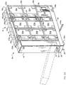
- a battery charger assembly 14 is mechanically coupled with a battery housing 15.
- Battery charger assembly 14 is preferably pivotally mounted so that the entire assembly may rotate downward, as indicated in phantom. The charger assembly 14 may also be completely removed.
- the battery housing 15 includes a load-bearing frame which is formed by a top member 16, shelves 18a and 18b, a bottom member 19 and vertical supports 22a-22d.
- the top member 16 includes a channel 17 which increases the strength and stiffness of the member 16.
- the channel 17 may engage with a rail, extending downwardly from beneath the switches 5 ( Figure 1), for securing the module 6a in a fixed position when installed in the cabinet 4.
- Each battery has external screw-type terminals, a representative one of which is denoted by reference numeral 21, which are located at two adjacent corners.
- the interior sidewalls and rear bottoms of the eight battery compartments may include upwardly extending flanges to provide a containment for each battery 20.
- a piece of resilient insulating material may be wedged between each battery 20 and the top of its compartment.
- a panel 34 covers the ninth compartment, which houses an output power connector 35.
- the interior side of power connector 35 is connected by wires or cables 37 to appropriate terminals on the batteries 20 and to charger assembly 14.
- the exterior side of connector 35 is connectable to a desired load.
- a handle 30 is connected to the front of the module 6a below the battery charger assembly 14.
- a locking pin access aperture 32, from which a lock-actuating lever 33 protrudes, is located just above the handle 30.
- Three transparent insulating and retaining members 36a, 36b and 36c are secured to the side of the battery housing 15.
- Member 36c is preferably shaped similarly to member 36a, but shorter in length to avoid overlapping and interfering with panel 34.
- Slots 37a, 37b and 37c in the top member 16 permit insertion of the members 36a, 36b and 36c, respectively, from above. Similar slots are also provided in shelves 18a and 18b and the bottom member 19.
- a bus bar 38a which electrically connects the lower terminal of battery 20e to the upper terminal of battery 20h, is visible through transparent member 36b.
- Bus bars of varying shapes discussed in detail below in connection with Figures 5A, 5B and 5C, are preferably used to connect the batteries 20 in series and to interconnecting wires.
- FIG. 2B shows the battery housing 15 of Figure 2A with several portions removed and schematically illustrates the electrical interconnections between the batteries 20a-20h and the output power connector 35.
- the batteries 20a-20h are connected in series and are advantageously arranged such that terminals of opposite polarity are adjacent to each other, thereby providing a minimum distance for a terminal-to-terminal connection.
- Many of the terminal-to-terminal connections are thus made by bus bars such as bus bar 38a.
- a bus bar 38b is shaped to span the vertical support 22c and provide a terminal-to-terminal connection between batteries 20b and 20c.
- a bus bar 38c is shaped to secure an interconnecting wire 39 to the negative terminal of battery 20a.
- the output power connector 35 includes a negative terminal (-), a positive terminal (+) and a center tap or center position terminal (CP).
- the negative terminal is connected by two wires 37 to the charger assembly and to the bus bar 38c, respectively.
- the positive terminal is connected via a fuse F to the positive terminal of battery 20f.
- the CP terminal is connected via a load resistor R to the bus bar 38a.
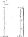
- Figures 3A, 3B and 3C are enlarged views of insulating and retaining member 36b.
- An aperture 40 disposed in the upper end of the member 36b is provided for improved ease of handling during installation or removal of the member 36b from the battery housing 15.
- Notches 42 and 44 abut the bottom member 19 ( Figure 2A) when member 36b is installed, thereby preventing the member 36b from sliding downwardly.
- a notch 46, located near the top edge of the member 36b, is shaped to engage with a tab which extends inwardly within slot 37b, thereby preventing the member 36b from moving upwardly and essentially locking the member in place.
- Member 36b is preferably L-shaped in cross-section, which advantageously increases the stiffness of the member, as well as allowing the member to restrict movement of the batteries 20 in two axes (i.e., sideways within the compartments and forward out of the compartments).
- Members 36a, 36b and 36c are preferably constructed from a polycarbonate material, which is both transparent and a good insulator. Material sold under the trademark LEXAN is suitable. Transparency is preferred so that, for example, a technician may visually inspect the battery terminals, bus bars and the like without removing the members.
- small through holes may be placed in the members, in alignment with the battery terminals, for test purposes. For maximum safety, such holes should be large enough to accommodate a test probe, but not large enough to admit a finger.
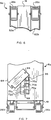
- FIG. 4A and 4B the stabilizer 24b is shown in the retracted position.
- a lower edge 48 of bottom member 19 is shaped to allow the outboard portions of the stabilizers 24 to clear when they retract.
- An outlock member 53 is disposed adjacent to each stabilizer 24 (only member 53b being visible in Figure 4A).
- Outlock member 53b includes a free end 55b which includes a notch 57b shaped to engage the top surface of the stabilizer 24b.
- a strap 59b permits the free end 55b to move vertically, but prevents lateral movement away from the side of the bottom member 19.
- a pivot end 61b is preferably pivotally attached to the bottom member 19, thereby allowing the free end 55b to move up or down.
- each stabilizer 24 extends vertically through a corresponding brace 58, the top surface of the bottom member 19 and a retaining member 52.
- the inboard end of each stabilizer 24 is fitted with a spring 54 which is connected between the retaining member 52 and a pin 56.
- Each spring 54 creates a torsional biasing force on its associated stabilizer 24. In the absence of a counterbalancing force produced by a guide rail 10, as explained in detail below, this biasing force automatically forces the stabilizer 24 below the lower edge 48 of the bottom member 19. Once clear of the bottom member 19, the stabilizer 24 swings freely outward into a deployed position and locks.
- a raceway 60 which extends laterally along the length of the bottom member 19, is provided for routing wires and cables, such as wires 37 in Figures 2A and 2B, needed to interconnect the charger assembly 14 and batteries 20 with the output power connector 35 ( Figure 2A).
- Bus bar 38a is used to make a "straight" terminal-to-terminal connection between two terminals of opposite polarity such as those of batteries 20e and 20h.
- Bus bar 38a also includes two holes 62 which may be used, in combination with conventional lugs or other fasteners (not shown), for connecting wires.
- bus bar 38b is specially shaped to span the vertical support 22c to connect the upper terminals of batteries 20b and 20c, which are shown in phantom.
- Bus bar 38c is shaped to connect the negative terminal of battery 20a and to a wire 37 which is routed to the output power connector 35.
- the slots in all of the bus bars 38 are preferably oriented such that each slides easily onto the battery terminals without having to completely remove the terminal screws. Further, such orientation tends to prevent the bars 38 from falling off when the terminal screws are loose.
- Figure 6 shows an enlarged partial plan view of the bottom of module 6a of Figure 2A.
- Bottom member 19 is shaped so as to form to channels or recessed areas 62a and 62b, which provide sufficient clearance to accomodate wheels 26b and 26c. Such clearance advantageously tends to reduce the overall height of the module 6a. Further, the sidewalls of the channels 62a and 62b provide suitable mounting points for the wheels.
- Figure 7 is a enlarged partial elevation of module 6a showing the output power connector 35 and a rotatable safety cover 64.
- Cover 64 is preferably pivotally attached at a point 66 and has one end shaped to engage with a post 68 when fully closed. Cover 64 may be closed when the module 6a is free standing outside of its cabinet in order to prevent accidental contact with the energized power connector 35.
- Power connector 35 includes three terminals 70a, 70b and 70c and two apertures 72a and 72b.
- Apertures 72a and 72b are preferably located and shaped to engage with corresponding guide pins (not shown) which are located within the interior of the cabinet 4 ( Figure 1).
- guide pins engage the apertures 72a and 72b to ensure that power connector 35 is properly aligned with its mate within the cabinet.
- the insulating and retaining members 36 are installed next. This is accomplished, for example, by raising the member 36 above the module 6 in a vertical orientation, inserting the edge of the member 36 into the appropriate slot 37 and lowering the member until it locks into place. Once installed, the members 36 abut the batteries 20 and inhibit lateral movement of the batteries 20 from their respective compartments. The charger assembly 14 is now rotated to a fully upright position.
- the module 6 is now ready for installation in the cabinet 4.
- the handle 30 the module 6 is aligned with one of the channels 8.
- a ramp or pallet may be used as an aid for rolling the module 6 into its channel in the cabinet 4.
- the guide rails 10 eventually make contact with the deployed stabilizers 24. This initial contact exerts an inward force on the stabilizers 24, which force overcomes the torsional bias created by the springs 54 ( Figure 4B) and unlocks the stabilizers 24.
- the guide rails 10 exert lateral forces on the unlocked stabilizers 24 which "sweep back" and retract the stabilizers.
- the locking pin 28 may be lowered into a corresponding aperture 12 by manually sliding the lever 33 in a lateral direction.
Landscapes
- Chemical & Material Sciences (AREA)
- Chemical Kinetics & Catalysis (AREA)
- Electrochemistry (AREA)
- General Chemical & Material Sciences (AREA)
- Engineering & Computer Science (AREA)
- Manufacturing & Machinery (AREA)
- Microelectronics & Electronic Packaging (AREA)
- Charge And Discharge Circuits For Batteries Or The Like (AREA)
- Battery Mounting, Suspending (AREA)
- Secondary Cells (AREA)
Abstract

Description
- The present invention relates generally to the field of battery back-up power sources for electronic equipment and, more specifically, to a modular housing for holding batteries and a battery charger which function as a battery power source.
- Many types of electronic equipment are powered by batteries to achieve desired functionality. In smaller equipment, such as laptop computers, it is often desirable to use a battery power source for portability. Larger equipment, such as a "minicomputer" or mainframe computer, may rely on a battery power source as a back-up which is switched on-line during a failure in the primary source of supply (i.e., the local electric utility). Such "uninterruptable" power sources are thus intended to maintain a continuous supply of power in order to prevent or reduce down time of costly, critical equipment and also prevent loss of data during interruptions of utility supplied power.
- However, conventional battery power sources, particularly those designed to power larger systems, often exhibit one or more of the following disadvantages. First, conventional battery sources are generally not based on a modular architecture, are often difficult to install or replace and cannot be readily interconnected to meet the power requirements of different types of equipment. Further, great difficulty and inconvenience are often encountered when attempting to install or replace individual batteries.
- Second, the physical size of the battery power source is often an important consideration in many applications and conventional sources are typically large and bulky. Thus, such conventional sources may be unusable in applications having stringent space or form factor constraints.
- Third, safety considerations are of paramount importance in terms of protecting personnel from injury and protecting the power source from damage, protecting yet many conventional power sources do not adequately guard against these risks. Obviously, there is an electrical shock and energy hazard presented by any battery power source, particularly those powering larger loads which may operate at several hundred volts. Moreover, 12V batteries connected in series to produce 96V tend to be quite heavy due to their internal construction. Conventional battery power sources may not provide sufficient load-bearing capacity to combine several such batteries into a single compact package.
- Lastly, many conventional battery power sources require a battery charger that is manufactured or supplied as a separate assembly which must be electrically connected with the power source. Separate chargers often represent an increased safety risk due to exposed cables needed for interconnection.
- The present invention in its broad form resides in a housing for holding a plurality of batteries, generally as recited in
claim 1. - Described hereinafter is a housing for batteries which may be combined with a battery charger in a mechanically integrated module. The module permits rapid, easy installation or removal of individual batteries as well as provides enhanced operating safety in terms of shock protection and mechanical stability. The module is compact, easily transported and easily installed by simpling rolling the module into a cabinet and actuating an in-lock device to secure it in position.
- The module includes a load-bearing frame, battery retaining members, and mechanical stabilizers and wheels attached to the base of the frame. The frame includes a number of compartments arranged in a vertical array. Several compartments are adapted to hold individual batteries and one is reserved for electrically interconnecting the batteries with an output power connector. Solid bus bars in various configurations are provided to electrically connect battery terminals to other terminals or to wires. The base of the frame includes a raceway or channel for routing interconnecting wires between the charger assembly, batteries and output power connector.
- The battery-retaining members permit rapid, easy installation or removal of individual batteries from the housing as well as inhibiting lateral movement of the batteries within their respective compartments. In addition, the retaining members serve as insulators which protectively cover the battery terminals to prevent accidental contact by personnel or other equipment located in close proximity to the module.
- The stabilizers deploy automatically as the module is withdrawn from its cabinet and provide mechanical stability when the module is free standing. Conversely, when the module is installed within the cabinet, the stabilizers automatically retract, thereby reducing the space occupied by the module. The in-lock device mounted on the bottom of the frame secures the module in a fixed position within the cabinet.
- The battery charger assembly is pivotally mounted to one end of the module frame to allow easy access to the electrical interconnections between the batteries and charger assembly. This arrangement also permits the charger assembly to be completely removed from the frame, if desired.
- A more detailed understanding of the invention may be had from the following description of a preferred embodiment, given by way of example and to be understood in conjunction with the accompanying drawing wherein:
- Figure 1 is a perspective view of an uninterruptable power supply which incorporates integrated battery and battery charger modules constructed in accordance with a preferred embodiment of the present invention;
- Figure 2A is a perspective view of one of the integrated battery and battery charger modules shown in Figure 1;
- Figure 2B is a side elevation of the batteries shown in Figure 2A with schematic illustration of various electrical interconnections;
- Figures A, 3B and 3C show various enlarged views of one of the insulating and retaining members shown in Figure 2A;
- Figure 4A is an enlarged side view of the stabilizer assembly of Figure 2A in a retracted position;
- Figure 4B is a sectional view taken along
line 4B-4B of Figure 4A; - Figures 5A, 5B and 5C are enlarged views of various types of bus bars used to connect the terminals of the batteries shown in Figures 2A and 2B;
- Figure 6 is a partial bottom plan view of the module shown in Figure 2A;
and - Figure 7 is a partial side elevation of the module shown in Figure 2A.
- Figure 1 shows an uninterrupted power supply (UPS) 2. The UPS 2 may be used to continuously deliver electrical power to a desired load (not shown), such as computer system, by switching from a primary power supply to a battery power source upon failure of the primary supply. The upper portion of a
cabinet 4 houses several power converters which are designated generally byreference numeral 3. Thepower converters 3 convert AC line voltage provided by an electric power utility to appropriate voltages for powering the desired load. A series of switches, designated generally byreference numeral 5, are mounted in the middle portion of thecabinet 4. Theswitches 5 may operate, for example, to disconnect the AC line voltage from theUPS 2 or to disconnect theUPS 2 from the load. As thetransformers 3 andswitches 5 are germane to the present invention merely for purposes of demonstrating an exemplary use, they will not be discussed further. - Three integrated battery and
battery charger modules cabinet 4. Guide rails 10a-10f extend upward from the interior bottom surface 11 of thecabinet 4 and define a series of "channels," each of which may accommodate a module 6. Threechannels cabinet 4 depending upon the power requirements of the load or loads powered by the UPS 2. Other applications may, of course, present different requirements. Advantageously, each module 6 may be installed or removed independently from the other modules, thus facilitating assembly, expansion and maintenance procedures. - Apertures 12a-12f are located near the front edge of the surface 11 and are used for locking the modules 6 in place within the
cabinet 4, as explained in detail below. - As shown in Figure 2A, which is a perspective view of a representative one of the modules 6 of Figure 1, a battery charger assembly 14 is mechanically coupled with a
battery housing 15. Battery charger assembly 14 is preferably pivotally mounted so that the entire assembly may rotate downward, as indicated in phantom. The charger assembly 14 may also be completely removed. - The
battery housing 15 includes a load-bearing frame which is formed by atop member 16,shelves 18a and 18b, abottom member 19 and vertical supports 22a-22d. Thetop member 16 includes achannel 17 which increases the strength and stiffness of themember 16. In addition, thechannel 17 may engage with a rail, extending downwardly from beneath the switches 5 (Figure 1), for securing themodule 6a in a fixed position when installed in thecabinet 4. - Nine rectangular compartments are defined by the load-bearing frame, eight of which house batteries 20a-20h, respectively. Each battery has external screw-type terminals, a representative one of which is denoted by
reference numeral 21, which are located at two adjacent corners. The interior sidewalls and rear bottoms of the eight battery compartments may include upwardly extending flanges to provide a containment for each battery 20. To provide even greater containment of the batteries, a piece of resilient insulating material may be wedged between each battery 20 and the top of its compartment. - A
panel 34, a portion of which is cut away in the drawing, covers the ninth compartment, which houses anoutput power connector 35. The interior side ofpower connector 35 is connected by wires orcables 37 to appropriate terminals on the batteries 20 and to charger assembly 14. The exterior side ofconnector 35 is connectable to a desired load. - Attached to the underside of the
bottom member 19 are two laterally-extending stabilizers 24 (only 24a being visible in Figure 2A), four wheels 26 (26a and 26b being visible) and alocking pin 28. A handle 30 is connected to the front of themodule 6a below the battery charger assembly 14. A lockingpin access aperture 32, from which a lock-actuatinglever 33 protrudes, is located just above the handle 30. - Three transparent insulating and retaining
members battery housing 15.Member 36c is preferably shaped similarly tomember 36a, but shorter in length to avoid overlapping and interfering withpanel 34.Slots 37a, 37b and 37c in thetop member 16 permit insertion of themembers shelves 18a and 18b and thebottom member 19. - A
bus bar 38a, which electrically connects the lower terminal ofbattery 20e to the upper terminal ofbattery 20h, is visible throughtransparent member 36b. Bus bars of varying shapes, discussed in detail below in connection with Figures 5A, 5B and 5C, are preferably used to connect the batteries 20 in series and to interconnecting wires. - Figure 2B shows the
battery housing 15 of Figure 2A with several portions removed and schematically illustrates the electrical interconnections between the batteries 20a-20h and theoutput power connector 35. The batteries 20a-20h are connected in series and are advantageously arranged such that terminals of opposite polarity are adjacent to each other, thereby providing a minimum distance for a terminal-to-terminal connection. Many of the terminal-to-terminal connections are thus made by bus bars such asbus bar 38a. Abus bar 38b is shaped to span thevertical support 22c and provide a terminal-to-terminal connection betweenbatteries bus bar 38c is shaped to secure an interconnecting wire 39 to the negative terminal of battery 20a. - The
output power connector 35 includes a negative terminal (-), a positive terminal (+) and a center tap or center position terminal (CP). The negative terminal is connected by twowires 37 to the charger assembly and to thebus bar 38c, respectively. The positive terminal is connected via a fuse F to the positive terminal ofbattery 20f. The CP terminal is connected via a load resistor R to thebus bar 38a. - Figures 3A, 3B and 3C are enlarged views of insulating and retaining
member 36b. Anaperture 40 disposed in the upper end of themember 36b is provided for improved ease of handling during installation or removal of themember 36b from thebattery housing 15.Notches member 36b is installed, thereby preventing themember 36b from sliding downwardly. Anotch 46, located near the top edge of themember 36b, is shaped to engage with a tab which extends inwardly withinslot 37b, thereby preventing themember 36b from moving upwardly and essentially locking the member in place. -
Member 36b is preferably L-shaped in cross-section, which advantageously increases the stiffness of the member, as well as allowing the member to restrict movement of the batteries 20 in two axes (i.e., sideways within the compartments and forward out of the compartments).Members - Turning now to Figures 4A and 4B, the
stabilizer 24b is shown in the retracted position. Alower edge 48 ofbottom member 19 is shaped to allow the outboard portions of the stabilizers 24 to clear when they retract. An outlock member 53 is disposed adjacent to each stabilizer 24 (onlymember 53b being visible in Figure 4A).Outlock member 53b includes afree end 55b which includes anotch 57b shaped to engage the top surface of thestabilizer 24b. Astrap 59b permits thefree end 55b to move vertically, but prevents lateral movement away from the side of thebottom member 19. A pivot end 61b is preferably pivotally attached to thebottom member 19, thereby allowing thefree end 55b to move up or down. Thus, whenstabilizer 24b is retracted,free end 55b is raised up as shown and thestabilizer 24b is not locked. Conversely, whenstabilizer 24b is deployed,free end 55b moves downward to rest on top of the stabilizer and lock it in position. - The inboard portion of each stabilizer 24 extends vertically through a corresponding brace 58, the top surface of the
bottom member 19 and a retainingmember 52. The inboard end of each stabilizer 24 is fitted with a spring 54 which is connected between the retainingmember 52 and a pin 56. Each spring 54 creates a torsional biasing force on its associated stabilizer 24. In the absence of a counterbalancing force produced by a guide rail 10, as explained in detail below, this biasing force automatically forces the stabilizer 24 below thelower edge 48 of thebottom member 19. Once clear of thebottom member 19, the stabilizer 24 swings freely outward into a deployed position and locks. - A
raceway 60, which extends laterally along the length of thebottom member 19, is provided for routing wires and cables, such aswires 37 in Figures 2A and 2B, needed to interconnect the charger assembly 14 and batteries 20 with the output power connector 35 (Figure 2A). - Referring now to Figures 2B, 5A 5B and 5C, various configurations of bus bars are shown which are preferably used to connect battery terminals to each other or to wires or cables, as applicable.
Bus bar 38a is used to make a "straight" terminal-to-terminal connection between two terminals of opposite polarity such as those ofbatteries Bus bar 38a also includes twoholes 62 which may be used, in combination with conventional lugs or other fasteners (not shown), for connecting wires. - In contrast,
bus bar 38b is specially shaped to span thevertical support 22c to connect the upper terminals ofbatteries -
Bus bar 38c is shaped to connect the negative terminal of battery 20a and to awire 37 which is routed to theoutput power connector 35. - The slots in all of the bus bars 38 are preferably oriented such that each slides easily onto the battery terminals without having to completely remove the terminal screws. Further, such orientation tends to prevent the bars 38 from falling off when the terminal screws are loose.
- Figure 6 shows an enlarged partial plan view of the bottom of
module 6a of Figure 2A.Bottom member 19 is shaped so as to form to channels or recessedareas wheels module 6a. Further, the sidewalls of thechannels - Figure 7 is a enlarged partial elevation of
module 6a showing theoutput power connector 35 and arotatable safety cover 64.Cover 64 is preferably pivotally attached at apoint 66 and has one end shaped to engage with apost 68 when fully closed.Cover 64 may be closed when themodule 6a is free standing outside of its cabinet in order to prevent accidental contact with the energizedpower connector 35. -
Power connector 35 includes threeterminals module 6a is rolled into thecabinet 4, the guide pins engage the apertures 72a and 72b to ensure thatpower connector 35 is properly aligned with its mate within the cabinet. - Assembly and installation of a module 6 will now be described with reference to Figure 2A. Assume initially that all of the batteries 20 and members 36 have been removed from the
battery housing 15 and that charger assembly 14 is rotated downward as shown in phantom. The stabilizers 24 are deployed. First, batteries 20 are placed into their respective compartments. Bus bars 38 are then used to connect the batteries' terminals. Interconnecting wires or cables are then routed, via theraceway 60, from the charger assembly 14 for connection to an appropriate bus bar 38, battery terminal or theoutput power connector 35. With the charger assembly 14 rotated downward, access is easily gained to the space between the assembly 14 andhousing 15 and theraceway 60, thus expediting the routing of necessary wires or cables. For enhanced safety, a transparent insulating panel (not shown) may cover the portion of the charger assembly 14 which is exposed when the assembly is rotated downward. Such a panel provides both protection against shock hazard and permits visual inspection of the interior of the assembly 14. - The insulating and retaining members 36 are installed next. This is accomplished, for example, by raising the member 36 above the module 6 in a vertical orientation, inserting the edge of the member 36 into the
appropriate slot 37 and lowering the member until it locks into place. Once installed, the members 36 abut the batteries 20 and inhibit lateral movement of the batteries 20 from their respective compartments. The charger assembly 14 is now rotated to a fully upright position. - Referring now to Figures 1 and 2, the module 6 is now ready for installation in the
cabinet 4. Using the handle 30, the module 6 is aligned with one of the channels 8. A ramp or pallet may be used as an aid for rolling the module 6 into its channel in thecabinet 4. As the module 6 rolls into the channel, the guide rails 10 eventually make contact with the deployed stabilizers 24. This initial contact exerts an inward force on the stabilizers 24, which force overcomes the torsional bias created by the springs 54 (Figure 4B) and unlocks the stabilizers 24. As the module 6 continues to roll into the channel, the guide rails 10 exert lateral forces on the unlocked stabilizers 24 which "sweep back" and retract the stabilizers. - Once the module 6 is rolled completely into the
cabinet 4, the lockingpin 28 may be lowered into a corresponding aperture 12 by manually sliding thelever 33 in a lateral direction. - The foregoing description has been limited to a specific embodiment of this invention. It will be apparent, however, that variations and modifications may be made to the invention, with the attainment of some or all of the advantages of the invention. Therefore, it is the object of the appended claims to cover all such variations and modifications as come within the true spirit and scope of the invention.
Claims (10)
- A housing for holding a plurality of batteries which represent part of a power supply, said housing comprising:
a load-bearing frame having a plurality of compartments, one or more of said compartments being adapted for holding a battery having external terminals;
one or more insulating means for insulating the terminals of the batteries from the ambient environment and for inhibiting movement of the batteries within the compartments; and
one or more stabilizers secured to said frame and deployable to enhance said housing's mechanical stability,
further comprising a battery charger attached to said frame, said charger being electrically connectable with one or more of said batteries and with input and output power connectors, and bus bars in said housing, disposed to selectively connect in use said plurality of batteries as desired. - The housing as in claim 1 wherein said charger is pivotally mounted on said frame, whereby said charger includes means to enable being pivoted away from said frame to allow access to a space between said charger and frame and may be removed from said frame.
- The housing as in claim 1 wherein said insulating means are removable to permit installation or removal of one or more of said batteries, wherein said batteries are held in said compartments such that the terminals are generally vertically aligned and the insulating means comprises an elongated member which is fastened to said frame adjacent to said terminals, wherein said frame includes a bottom portion having a raceway for routing electrical wires within said housing.
- The housing as in claim 1 further comprising means for locking the housing in a fixed position within an external cabinet.
- The housing as in claim 1 wherein said compartments are generally rectangular in shape and arranged in a series of rows and columns, wherein said housing is mobile, wherein also, said housing is a module in a modular battery power source.
- The housing as in claim 5 wherein said module is installable in a cabinet, said cabinet including means for automatically retracting said stabilizers when said module is installed.
- A mechanically integrated battery power source and battery charger comprising:
a mobile load-bearing frame having a plurality of compartments, one or more of said compartments for holding a rechargeable battery having external terminals;
a battery charger secured to said frame, said charger electrically connected with at least one rechargeable battery and with input and output power connectors;
one or more means for insulating the terminals of the batteries and for inhibiting movement of said batteries within the compartments; and
one or more stabilizers mechanically secured to said frame and deployable when said apparatus is free-standing to enhance mechanical stability and retractable when said apparatus is secured in a fixed position. - The apparatus as in claim 7 wherein said one or more stabilizers include means for automatically deploying when said apparatus is free-standing and for automatically retracting when said apparatus is secured in a fixed position, wherein said insulating means are removable to permit installation or removal of one or more of said batteries, wherein said batteries are held in said compartments such that the terminals are generally vertically aligned and the insulating means comprises an elongated member which is fastened to said frame adjacent to said terminals.
- The apparatus as in claim 7 wherein said frame includes a bottom portion having a raceway for routing electrical wires within said apparatus, further comprising means for locking the apparatus in a fixed position within a cabinet, further comprising one or more bus bars for electrically connecting a terminal of one battery to a terminal of another battery or to a wire.
- The apparatus as in claim 7 wherein said mechanically integrated battery power source and battery charger is a module in a modular battery power source, wherein said module is installable in a cabinet, said cabinet including means for automatically retracting said stabilizers when said module is installed.
Applications Claiming Priority (2)
| Application Number | Priority Date | Filing Date | Title |
|---|---|---|---|
| US07/896,251 US5366827A (en) | 1992-06-10 | 1992-06-10 | Modular housing for batteries and battery charger |
| US789251 | 2001-02-20 |
Publications (2)
| Publication Number | Publication Date |
|---|---|
| EP0574261A1 true EP0574261A1 (en) | 1993-12-15 |
| EP0574261B1 EP0574261B1 (en) | 1997-01-29 |
Family
ID=25405886
Family Applications (1)
| Application Number | Title | Priority Date | Filing Date |
|---|---|---|---|
| EP93304521A Expired - Lifetime EP0574261B1 (en) | 1992-06-10 | 1993-06-10 | Battery power module |
Country Status (4)
| Country | Link |
|---|---|
| US (1) | US5366827A (en) |
| EP (1) | EP0574261B1 (en) |
| JP (1) | JPH06163017A (en) |
| DE (1) | DE69307781T2 (en) |
Cited By (4)
| Publication number | Priority date | Publication date | Assignee | Title |
|---|---|---|---|---|
| EP0662725A1 (en) * | 1994-01-06 | 1995-07-12 | Gnb Industrial Battery Company | Sealed lead-acid battery tray assemblies and motive power vehicles using such battery tray assemblies |
| WO1998056054A1 (en) * | 1997-06-02 | 1998-12-10 | Gnb Technologies, Inc. | Modular cell tray assembly for sealed lead-acid cells |
| CN108987638A (en) * | 2018-07-24 | 2018-12-11 | 毛秋菊 | A kind of New-energy electric vehicle battery pack |
| CN110603660A (en) * | 2017-04-25 | 2019-12-20 | 荷派克电源有限两合公司 | System comprising a holder and an energy storage source that can be placed in the holder |
Families Citing this family (75)
| Publication number | Priority date | Publication date | Assignee | Title |
|---|---|---|---|---|
| US5814968A (en) * | 1995-06-26 | 1998-09-29 | Long Range Systems, Inc. | Battery charger and rechargeable electronic paging device assembly |
| US5806948A (en) * | 1997-06-16 | 1998-09-15 | Rowan, Sr.; W. Frank | Retrofittable battery cabinet for telecommunications enclosures |
| GB9722890D0 (en) * | 1997-10-31 | 1998-01-07 | Brook Chrispin Kenneth | Battery charging rack |
| US6262894B1 (en) * | 1998-06-30 | 2001-07-17 | Emc Corporation | Electrical cabinet having an extendable bracket supporting a battery |
| US6162559A (en) * | 1998-09-21 | 2000-12-19 | Douglas Battery Manufacturing Company | Compressed battery system for motive power applications |
| US6641951B1 (en) * | 1998-09-21 | 2003-11-04 | Douglas Battery Manufacturing Company | Battery cell tray assembly and sytem |
| DE29903353U1 (en) * | 1999-02-25 | 1999-08-26 | Apfel GmbH Metallverarbeitung, 69221 Dossenheim | Tool and / or material cabinet |
| US6361897B1 (en) | 1999-06-22 | 2002-03-26 | Enersys Inc. | Dual terminal battery for modular power supply and power supply |
| US6657320B1 (en) * | 1999-11-03 | 2003-12-02 | Active Power, Inc. | Integrated flywheel uninterruptible power supply system |
| US6436570B1 (en) * | 2000-05-10 | 2002-08-20 | Subhas Chandra Chalasani | Electrical distribution system for composite battery stand and composite battery stand incorporating the same |
| US6719150B2 (en) * | 2001-05-30 | 2004-04-13 | Kim Manufacturing Company | Battery rack and system |
| US7332889B2 (en) * | 2001-11-09 | 2008-02-19 | Milwaukee Electric Tool Corporation | Battery charger |
| US7740142B2 (en) * | 2001-11-20 | 2010-06-22 | Concorde Battery Corporation | Battery construction for mounting a shelved rack |
| US6836030B2 (en) * | 2002-05-31 | 2004-12-28 | Verari Systems, Inc. | Rack mountable computer component power distribution unit and method |
| US6909611B2 (en) | 2002-05-31 | 2005-06-21 | Verari System, Inc. | Rack mountable computer component and method of making same |
| US6867966B2 (en) | 2002-05-31 | 2005-03-15 | Verari Systems, Inc. | Method and apparatus for rack mounting computer components |
| US20040124753A1 (en) * | 2002-08-29 | 2004-07-01 | Stoller Harry R. | Storage unit with rolling tray arrangement for heavy loads |
| AU2003266017A1 (en) * | 2002-09-25 | 2004-04-23 | Racksaver, Inc. | Electronic component rack assembly and method |
| DE20218688U1 (en) | 2002-12-03 | 2003-07-10 | GSG Golf Service GmbH, 45136 Essen | Compact locker for an electric caddie with a battery and charging device has a stable sheet steel casing, a damp-proof socket, an electric connection wire and a cylinder lock |
| US20050024021A1 (en) * | 2003-05-07 | 2005-02-03 | Milwaukee Electric Tool Corporation | Battery charger and assembly |
| US7548429B2 (en) * | 2004-06-18 | 2009-06-16 | Douglas Battery Manufacturing Company | Battery storage system |
| US20050281002A1 (en) * | 2004-06-18 | 2005-12-22 | Miller Russell L | Battery storage system |
| US7427156B2 (en) * | 2004-12-20 | 2008-09-23 | Odyne Corporation | Thermally managed battery enclosure for electric and hybrid electric vehicles |
| CA2531295C (en) * | 2004-12-22 | 2013-10-22 | Odyne Corporation | Battery management and equalization system for batteries using power line carrier communications |
| CA2531656A1 (en) * | 2004-12-29 | 2006-06-29 | Odyne Corporation | Battery enclosure for electric and hybrid electric vehicles optimized for air cooling |
| US7830117B2 (en) | 2005-01-10 | 2010-11-09 | Odyne Systems, Llc | Vehicle charging, monitoring and control systems for electric and hybrid electric vehicles |
| GB2427970A (en) * | 2005-07-02 | 2007-01-10 | Stanley Ernest Harper | A cabinet for the recharging of a plurality of electrical batteries |
| US8100271B2 (en) * | 2006-02-02 | 2012-01-24 | C & C Power | Tiered battery cabinet |
| KR100920210B1 (en) * | 2006-02-09 | 2009-10-05 | 주식회사 엘지화학 | Frame member for battery module manufacturing |
| KR100861713B1 (en) * | 2006-02-09 | 2008-10-06 | 주식회사 엘지화학 | Battery module |
| WO2007102670A1 (en) | 2006-03-06 | 2007-09-13 | Lg Chem, Ltd. | Middle or large-sized battery module |
| KR100948002B1 (en) | 2006-03-06 | 2010-03-18 | 주식회사 엘지화학 | Medium and large battery module |
| JP5154454B2 (en) | 2006-03-06 | 2013-02-27 | エルジー・ケム・リミテッド | Battery module |
| US9484591B2 (en) | 2006-03-06 | 2016-11-01 | Lg Chem, Ltd. | Voltage sensing member and battery module employed with the same |
| DE102006041326B3 (en) * | 2006-09-01 | 2008-01-31 | Varta Automotive Systems Gmbh | Electric storage battery |
| KR101217459B1 (en) * | 2006-09-25 | 2013-01-02 | 주식회사 엘지화학 | battery module assembly |
| US8408341B2 (en) | 2007-07-12 | 2013-04-02 | Odyne Systems, Llc | Hybrid vehicle drive system and method and idle reduction system and method |
| US8818588B2 (en) | 2007-07-12 | 2014-08-26 | Odyne Systems, Llc | Parallel hybrid drive system utilizing power take off connection as transfer for a secondary energy source |
| US9878616B2 (en) | 2007-07-12 | 2018-01-30 | Power Technology Holdings Llc | Hybrid vehicle drive system and method using split shaft power take off |
| US20120207620A1 (en) | 2007-07-12 | 2012-08-16 | Odyne Systems, LLC. | Hybrid vehicle drive system and method and idle reduction system and method |
| WO2013081657A1 (en) | 2011-12-02 | 2013-06-06 | Odyne Systems, Llc | System for and method of fuel optimization in a hybrid vehicle |
| US8978798B2 (en) | 2007-10-12 | 2015-03-17 | Odyne Systems, Llc | Hybrid vehicle drive system and method and idle reduction system and method |
| US9061680B2 (en) | 2007-07-12 | 2015-06-23 | Odyne Systems, Llc | Hybrid vehicle drive system and method for fuel reduction during idle |
| US8587150B2 (en) * | 2008-02-28 | 2013-11-19 | Deeya Energy, Inc. | Method and modular system for charging a battery |
| EP2351184A4 (en) * | 2008-10-10 | 2014-07-09 | Deeya Energy Technologies Inc | Method and apparatus for determining state of charge of a battery |
| TWI357865B (en) * | 2008-12-03 | 2012-02-11 | Ind Tech Res Inst | A swift pluggable and lockable battery structure |
| TWM379909U (en) * | 2009-12-23 | 2010-05-01 | sheng-xing Liao | Replaceable module for socket and socket with replaceable module |
| US20120115016A1 (en) * | 2010-11-04 | 2012-05-10 | Myung-Chul Kim | Battery module |
| US8852789B2 (en) | 2010-11-04 | 2014-10-07 | Samsung Sdi Co., Ltd. | Battery module having battery cell holder |
| US9209433B2 (en) | 2011-01-14 | 2015-12-08 | C&D Technologies, Inc. | Riveted module |
| JP5339492B2 (en) * | 2011-07-15 | 2013-11-13 | 日本電気株式会社 | Power storage device |
| US8824143B2 (en) * | 2011-10-12 | 2014-09-02 | International Business Machines Corporation | Combined power and cooling rack supporting an electronics rack(S) |
| JP2013101809A (en) * | 2011-11-08 | 2013-05-23 | Nissan Motor Co Ltd | Stationary electric power system |
| US11225240B2 (en) | 2011-12-02 | 2022-01-18 | Power Technology Holdings, Llc | Hybrid vehicle drive system and method for fuel reduction during idle |
| US12330657B2 (en) | 2011-12-02 | 2025-06-17 | Power Technology Holdings Llc | Hybrid vehicle drive system and method for fuel reduction during idle |
| US20130234575A1 (en) * | 2012-03-11 | 2013-09-12 | Intellibatt, Llc | Method and system for providing an electronic equipment cabinet usable for storing reserve power batteries |
| US8652678B2 (en) * | 2012-04-17 | 2014-02-18 | Vecture Inc. | Battery pack system |
| US20150155742A1 (en) * | 2012-11-29 | 2015-06-04 | Stevan M. Bailey | Battery storage rack |
| US9166425B1 (en) * | 2013-07-03 | 2015-10-20 | Billy White | Battery charging storage device |
| WO2015074074A1 (en) | 2013-11-18 | 2015-05-21 | Odyne Systems, Llc | Hybrid vehicle drive system and method using split shaft power take off |
| CN103972966B (en) * | 2014-05-14 | 2016-06-08 | 国家电网公司 | Moving emergency DC power cabinet |
| US10985420B2 (en) | 2016-01-22 | 2021-04-20 | Ford Global Technologies, Llc | Battery pack with slide-in battery assembly |
| KR102063938B1 (en) | 2016-08-12 | 2020-01-08 | 주식회사 엘지화학 | Secondary battery module having strap type frame and frame assembly for the same |
| MX394937B (en) * | 2016-09-12 | 2025-03-24 | Lithion Battery Inc | Rechargeable battery modules and rechargeable battery module handling methods |
| CA173341S (en) | 2016-09-12 | 2018-05-11 | Valence Tech Inc | Battery module |
| DE102016221405A1 (en) * | 2016-10-31 | 2018-05-03 | Siemens Aktiengesellschaft | Electrical device and method for its maintenance |
| DE102017202855A1 (en) | 2017-02-22 | 2018-09-13 | Siemens Aktiengesellschaft | battery cabinet |
| JP7203080B2 (en) | 2017-07-13 | 2023-01-12 | イーコントロールズ エルエルシー | Modular lithium-ion battery system for forklifts |
| DE102018201355A1 (en) * | 2018-01-30 | 2019-08-01 | Robert Bosch Gmbh | Battery module, battery pack containing this, as well as their use |
| DE102019109725B4 (en) * | 2019-04-12 | 2023-12-14 | Dr. Ing. H.C. F. Porsche Aktiengesellschaft | Battery module and system consisting of battery connectors and battery modules |
| JP2021103909A (en) * | 2019-12-24 | 2021-07-15 | 株式会社セイブ・ザ・プラネット | Storage battery unit, storage battery device and hybrid type power supply system |
| US12266953B1 (en) | 2020-08-17 | 2025-04-01 | Econtrols, Llc | Dual chemistry rechargeable battery system for use in electric APU-equipped commercial trucks |
| WO2022256730A1 (en) * | 2021-06-04 | 2022-12-08 | Econtrols, Llc | Lithium-ion battery charging system for fork lifts |
| JP7784263B2 (en) * | 2021-09-30 | 2025-12-11 | 積水化学工業株式会社 | How to install the energy storage element unit |
| USD1119753S1 (en) | 2023-12-05 | 2026-03-24 | David Michael Medinis | Power storage cabinet |
Citations (4)
| Publication number | Priority date | Publication date | Assignee | Title |
|---|---|---|---|---|
| DE19161C (en) * | TH. COAD in London | Innovations in battery cabinets | ||
| US3903404A (en) * | 1973-10-17 | 1975-09-02 | Amdahl Corp | Computer construction and method |
| FR2601162A1 (en) * | 1986-04-29 | 1988-01-08 | Modular Power Corp | Modular electronic power supply |
| EP0362083A1 (en) * | 1988-09-29 | 1990-04-04 | Merlin Gerin | Modular rack for the batteries of electric accumulators |
Family Cites Families (6)
| Publication number | Priority date | Publication date | Assignee | Title |
|---|---|---|---|---|
| US3085127A (en) * | 1959-09-25 | 1963-04-09 | Motorola Inc | Battery retainer |
| US3110634A (en) * | 1961-06-29 | 1963-11-12 | Gould National Batteries Inc | Multiple cell battery case |
| JPS60236454A (en) * | 1984-04-28 | 1985-11-25 | Fujitsu Ltd | Battery compartment |
| US5140744A (en) * | 1990-06-06 | 1992-08-25 | Miller Robert D | Modular multicell battery and rack |
| JPH04283997A (en) * | 1991-03-13 | 1992-10-08 | Fujitsu Ltd | Battery containment box of electronic equipment |
| US5304434A (en) * | 1992-06-15 | 1994-04-19 | Gnb Industrial Battery Co. | Modular cabinet for large-sized sealed lead-acid cells |
-
1992
- 1992-06-10 US US07/896,251 patent/US5366827A/en not_active Expired - Lifetime
-
1993
- 1993-06-01 JP JP5130456A patent/JPH06163017A/en active Pending
- 1993-06-10 DE DE69307781T patent/DE69307781T2/en not_active Expired - Fee Related
- 1993-06-10 EP EP93304521A patent/EP0574261B1/en not_active Expired - Lifetime
Patent Citations (4)
| Publication number | Priority date | Publication date | Assignee | Title |
|---|---|---|---|---|
| DE19161C (en) * | TH. COAD in London | Innovations in battery cabinets | ||
| US3903404A (en) * | 1973-10-17 | 1975-09-02 | Amdahl Corp | Computer construction and method |
| FR2601162A1 (en) * | 1986-04-29 | 1988-01-08 | Modular Power Corp | Modular electronic power supply |
| EP0362083A1 (en) * | 1988-09-29 | 1990-04-04 | Merlin Gerin | Modular rack for the batteries of electric accumulators |
Non-Patent Citations (2)
| Title |
|---|
| PATENT ABSTRACTS OF JAPAN vol. 10, no. 95 (E-395)(2152) 12 April 1986 & JP-A-60 236 454 ( FUJITSU K.K. ) 25 November 1985 * |
| PATENT ABSTRACTS OF JAPAN vol. 17, no. 89 (E-1323)22 February 1993 & JP-A-04 283997 ( TANIGUCHI SHIYOUJIROU ) 8 October 1992 * |
Cited By (5)
| Publication number | Priority date | Publication date | Assignee | Title |
|---|---|---|---|---|
| EP0662725A1 (en) * | 1994-01-06 | 1995-07-12 | Gnb Industrial Battery Company | Sealed lead-acid battery tray assemblies and motive power vehicles using such battery tray assemblies |
| WO1998056054A1 (en) * | 1997-06-02 | 1998-12-10 | Gnb Technologies, Inc. | Modular cell tray assembly for sealed lead-acid cells |
| CN110603660A (en) * | 2017-04-25 | 2019-12-20 | 荷派克电源有限两合公司 | System comprising a holder and an energy storage source that can be placed in the holder |
| CN110603660B (en) * | 2017-04-25 | 2022-05-27 | 荷派克电源有限两合公司 | System comprising a holder and an energy storage source that can be placed in the holder |
| CN108987638A (en) * | 2018-07-24 | 2018-12-11 | 毛秋菊 | A kind of New-energy electric vehicle battery pack |
Also Published As
| Publication number | Publication date |
|---|---|
| DE69307781T2 (en) | 1997-08-21 |
| EP0574261B1 (en) | 1997-01-29 |
| US5366827A (en) | 1994-11-22 |
| DE69307781D1 (en) | 1997-03-13 |
| JPH06163017A (en) | 1994-06-10 |
Similar Documents
| Publication | Publication Date | Title |
|---|---|---|
| EP0574261B1 (en) | Battery power module | |
| EP0575060B1 (en) | Modular battery cabinet assembly | |
| US9072191B2 (en) | Configurable rack and related methods | |
| US5304434A (en) | Modular cabinet for large-sized sealed lead-acid cells | |
| US6563048B2 (en) | Ancillary cabinet system for an uninterruptible power supply | |
| ES2389647T3 (en) | Expandable and adjustable rack power system and procedure | |
| US12587022B2 (en) | Battery storage system with multi-level converter and multiple storage sections | |
| US7014946B2 (en) | Modular rack battery system | |
| AU2011352969A1 (en) | Configurable rack and related methods | |
| US20030039881A1 (en) | Battery accessible modules for rack mount systems | |
| US6317348B1 (en) | UPS chassis design having an internal support structure | |
| EP2036415B1 (en) | Electronic module and interlocking bus system including same | |
| US6518734B1 (en) | System and method of forming capacitor-based electrical energy storage modules | |
| CN100477335C (en) | Battery and assembled rack battery system | |
| JPH11317211A (en) | Cell tray assembly for lead-acid battery and cover system | |
| US6643122B1 (en) | Battery servicing system with bridging protection | |
| CN224097249U (en) | A high-voltage DC power supply cabinet | |
| US20250158564A1 (en) | Solar energy apparatus for modular buildings | |
| CN120895845A (en) | An electrode storage device for a battery-swapping mobile energy storage system | |
| SE2251267A1 (en) | Connector interface | |
| WARNING | Warnings and Notices | |
| AU2002332616A1 (en) | Battery accessible modules for rack mount systems | |
| Forlani | Integrated power station (power supply) |
Legal Events
| Date | Code | Title | Description |
|---|---|---|---|
| PUAI | Public reference made under article 153(3) epc to a published international application that has entered the european phase |
Free format text: ORIGINAL CODE: 0009012 |
|
| AK | Designated contracting states |
Kind code of ref document: A1 Designated state(s): DE FR GB IT |
|
| 17P | Request for examination filed |
Effective date: 19940614 |
|
| 17Q | First examination report despatched |
Effective date: 19950713 |
|
| GRAG | Despatch of communication of intention to grant |
Free format text: ORIGINAL CODE: EPIDOS AGRA |
|
| GRAH | Despatch of communication of intention to grant a patent |
Free format text: ORIGINAL CODE: EPIDOS IGRA |
|
| GRAH | Despatch of communication of intention to grant a patent |
Free format text: ORIGINAL CODE: EPIDOS IGRA |
|
| GRAA | (expected) grant |
Free format text: ORIGINAL CODE: 0009210 |
|
| AK | Designated contracting states |
Kind code of ref document: B1 Designated state(s): DE FR GB IT |
|
| REF | Corresponds to: |
Ref document number: 69307781 Country of ref document: DE Date of ref document: 19970313 |
|
| ITF | It: translation for a ep patent filed | ||
| ET | Fr: translation filed | ||
| PLBE | No opposition filed within time limit |
Free format text: ORIGINAL CODE: 0009261 |
|
| STAA | Information on the status of an ep patent application or granted ep patent |
Free format text: STATUS: NO OPPOSITION FILED WITHIN TIME LIMIT |
|
| 26N | No opposition filed | ||
| PGFP | Annual fee paid to national office [announced via postgrant information from national office to epo] |
Ref country code: FR Payment date: 19980520 Year of fee payment: 6 |
|
| PGFP | Annual fee paid to national office [announced via postgrant information from national office to epo] |
Ref country code: GB Payment date: 19980526 Year of fee payment: 6 |
|
| PGFP | Annual fee paid to national office [announced via postgrant information from national office to epo] |
Ref country code: DE Payment date: 19980527 Year of fee payment: 6 |
|
| PG25 | Lapsed in a contracting state [announced via postgrant information from national office to epo] |
Ref country code: GB Free format text: LAPSE BECAUSE OF NON-PAYMENT OF DUE FEES Effective date: 19990610 |
|
| PG25 | Lapsed in a contracting state [announced via postgrant information from national office to epo] |
Ref country code: FR Free format text: THE PATENT HAS BEEN ANNULLED BY A DECISION OF A NATIONAL AUTHORITY Effective date: 19990630 |
|
| GBPC | Gb: european patent ceased through non-payment of renewal fee |
Effective date: 19990610 |
|
| PG25 | Lapsed in a contracting state [announced via postgrant information from national office to epo] |
Ref country code: DE Free format text: LAPSE BECAUSE OF NON-PAYMENT OF DUE FEES Effective date: 20000503 |
|
| REG | Reference to a national code |
Ref country code: FR Ref legal event code: ST |
|
| PG25 | Lapsed in a contracting state [announced via postgrant information from national office to epo] |
Ref country code: IT Free format text: LAPSE BECAUSE OF NON-PAYMENT OF DUE FEES Effective date: 20050610 |