EP0573655B1 - Robot control method - Google Patents
Robot control method Download PDFInfo
- Publication number
- EP0573655B1 EP0573655B1 EP92923985A EP92923985A EP0573655B1 EP 0573655 B1 EP0573655 B1 EP 0573655B1 EP 92923985 A EP92923985 A EP 92923985A EP 92923985 A EP92923985 A EP 92923985A EP 0573655 B1 EP0573655 B1 EP 0573655B1
- Authority
- EP
- European Patent Office
- Prior art keywords
- robot
- load
- stopped
- shaft
- shafts
- Prior art date
- Legal status (The legal status is an assumption and is not a legal conclusion. Google has not performed a legal analysis and makes no representation as to the accuracy of the status listed.)
- Expired - Lifetime
Links
Images


Classifications
-
- B—PERFORMING OPERATIONS; TRANSPORTING
- B25—HAND TOOLS; PORTABLE POWER-DRIVEN TOOLS; MANIPULATORS
- B25J—MANIPULATORS; CHAMBERS PROVIDED WITH MANIPULATION DEVICES
- B25J9/00—Program-controlled manipulators
- B25J9/16—Program controls
- B25J9/1628—Program controls characterised by the control loop
- B25J9/1641—Program controls characterised by the control loop compensation for backlash, friction, compliance, elasticity in the joints
-
- B—PERFORMING OPERATIONS; TRANSPORTING
- B25—HAND TOOLS; PORTABLE POWER-DRIVEN TOOLS; MANIPULATORS
- B25J—MANIPULATORS; CHAMBERS PROVIDED WITH MANIPULATION DEVICES
- B25J13/00—Controls for manipulators
-
- G—PHYSICS
- G05—CONTROLLING; REGULATING
- G05B—CONTROL OR REGULATING SYSTEMS IN GENERAL; FUNCTIONAL ELEMENTS OF SUCH SYSTEMS; MONITORING OR TESTING ARRANGEMENTS FOR SUCH SYSTEMS OR ELEMENTS
- G05B2219/00—Program-control systems
- G05B2219/30—Nc systems
- G05B2219/39—Robotics, robotics to robotics hand
- G05B2219/39179—Of movement after lock stop by small movement against load, stop again
-
- G—PHYSICS
- G05—CONTROLLING; REGULATING
- G05B—CONTROL OR REGULATING SYSTEMS IN GENERAL; FUNCTIONAL ELEMENTS OF SUCH SYSTEMS; MONITORING OR TESTING ARRANGEMENTS FOR SUCH SYSTEMS OR ELEMENTS
- G05B2219/00—Program-control systems
- G05B2219/30—Nc systems
- G05B2219/42—Servomotor, servo controller kind till VSS
- G05B2219/42231—Detent, stop lock, current through motor in stop, locked, hold, blocked position
-
- G—PHYSICS
- G05—CONTROLLING; REGULATING
- G05B—CONTROL OR REGULATING SYSTEMS IN GENERAL; FUNCTIONAL ELEMENTS OF SUCH SYSTEMS; MONITORING OR TESTING ARRANGEMENTS FOR SUCH SYSTEMS OR ELEMENTS
- G05B2219/00—Program-control systems
- G05B2219/30—Nc systems
- G05B2219/45—Nc applications
- G05B2219/45083—Manipulators, robot
-
- G—PHYSICS
- G05—CONTROLLING; REGULATING
- G05B—CONTROL OR REGULATING SYSTEMS IN GENERAL; FUNCTIONAL ELEMENTS OF SUCH SYSTEMS; MONITORING OR TESTING ARRANGEMENTS FOR SUCH SYSTEMS OR ELEMENTS
- G05B2219/00—Program-control systems
- G05B2219/30—Nc systems
- G05B2219/49—Nc machine tool, till multiple
- G05B2219/49289—Large transmission ratio
Definitions
- This invention relates to a method for controlling a robot wherein the torque of a servo motor is transmitted to a robot arm by way of a speed reducer, and more particularly, to the holding of a load while the robot is in a stopped condition.
- the robots generally employ servo motors and the torque of the servo motors is usually transmitted to a robot arm by way of a speed reducer.
- the plurality of points on a path along which the robot arm passes are preliminarily taught and, at the time of playback, the robot is controlled by an interpolation of teaching points so that the robot arm moves along the path from one teaching point to another teaching point.
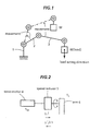
- Fig. 1 exemplifies such a movement, wherein numeral 1 indicates a first shaft, numeral 2 indicates a second shaft, numeral 3 indicates a third shaft and capital letter W indicates a load.
- the second shaft 2 moves in a direction to lift the load W and is stopped in the load lifting condition.
- no brake means is provided for maintaining the stopped condition.
- the load applied to the servo motor 4 for driving the shaft greatly differs between a case (a) in which the arm is moved in a load lifting direction and then is stopped while maintaining the load lifting condition and a case (b) in which the arm is moved while holding the load and then is stopped.
- the servo motor consumes a considerable amount of electricity and eventually increases the generation of heat which will adversely affect the accurate operation of the motor.
- the task to be achieved by this invention lies in stopping the robot under the condition (b), thus reducing the required torque of the servo motor and the generation of heat.
- This invention is enabled by the discovery that the efficiency (normal efficiency) of transmission from the servo motor to the arm (shaft) forms an inverse number relative to the efficiency (reverse efficiency) of transmission from the arm to the servo motor.
- the invention intentionally creates a condition in which the load is transmitted from the arm so as to make the load establish the equilibrium with the torque generated by the servo motor, thus reducing the consumption of electricity and the generation of heat.
- the directions of the dynamic loads which are applied to the respective shafts in a stopped condition are judged and, if the robot's stopped condition continues for a predetermined time, the shafts to which loads are applied are moved a minute distance in a direction opposite to the load acting direction and thereafter returned to the stopped position to obtain the condition (b).
- the load of the servo motor at the stopped condition can be reduced, the consumption of electricity is reduced and the generation of heat is reduced.
- the capacity of the servo motor can also be reduced.
- Fig. 1 is a schematic view of a robot having three shafts lifting a load.
- Fig. 2 is an explanatory view explaining the torque transmission from the servo motor to the arm.
- Fig. 3 is a block diagram showing by way of example a construction of a robot controlling apparatus.
- Fig. 4 is a flow chart showing one example of the method according to this invention.
- Fig. 3 is a block diagram showing the construction of a robot controlling apparatus. Motor control parameters are stored in a ROM 6 which is connected to an arithmetic CPU.
- control parameters which are transferred to the shared RAM 3 can be altered by an operator operating an I/O device 13 which is connected to a peripheral CPU 12.
- the control parameters which are stored in the shared RAM 3 are transferred to the shared RAM by the following path so that a servo CPU can have access to the control parameters.
- the program execution commands are transferred to the servo CPU by way of the bus 22, the shared RAM 4 and the bus 23 and the servo CPU 7 transfers control signals to a D/A converter 9 by way of a bus 25.
- the D/A converts digital signals to analog signals and provides speed commands to a servo amplifier 10.
- the servo amplifier 10 includes, for example, an inverter and provides torque commands to a servo motor 11 to drive a robot arm.
- Fig. 4 is a flow chart showing one embodiment of this invention which is executed by the servo CPU 7.
- step 100 whether the robot is stopped or not is judged in view of the deviation between a position feedback signal from the servo motor in Fig. 3 and a position command signal. If the robot is stopped, a timer is reset at step 110 and the load acting direction shafts are selected at step 120.
- the shafts which make the servo motor 11 generate torque to drive the robot arm in a direction opposite to gravity while the robot arm is stationary are selected as load acting direction shafts.
- a movement command of a minute distance for example, several pulses, are provided to the servo motor at step 140 to move the load acting direction shafts in a direction opposite to the load acting direction.
- the load acting direction shafts are moved.
- the movement command to return the load acting direction shafts to the original position is generated at step 160 and the load acting direction shafts are returned to the original position at step 170. If there exists a movement command in decision processing at step 180, the load acting direction shafts are moved at step 190 and are returned to the original position.
- a wait command is provided to the main CPU 1 from the servo CPU 7 and, after the completion of the processing at step 170, a reset signal for the wait command is generated so that interference to the operation of this invention by another program can be avoided.
- This invention can be utilized to control various industrial robots.
Landscapes
- Engineering & Computer Science (AREA)
- Robotics (AREA)
- Mechanical Engineering (AREA)
- Manipulator (AREA)
- Numerical Control (AREA)
- Control Of Position Or Direction (AREA)
Abstract
Description
- This invention relates to a method for controlling a robot wherein the torque of a servo motor is transmitted to a robot arm by way of a speed reducer, and more particularly, to the holding of a load while the robot is in a stopped condition. See for example H. Keinrichfreise "The control of an elastic manipulation device using DSP" Proceedings of the 1988 American Control Conference 17 June 88.
- Particularly among industrial robots, there are some which utilize hydraulics as drive means thereof. However, the robots generally employ servo motors and the torque of the servo motors is usually transmitted to a robot arm by way of a speed reducer.
- Meanwhile, in the teaching playback robot, the plurality of points on a path along which the robot arm passes are preliminarily taught and, at the time of playback, the robot is controlled by an interpolation of teaching points so that the robot arm moves along the path from one teaching point to another teaching point.
- Conventionally, when the robot moves from one teaching point to another teaching point, once the robot reaches a target point, the robot is stopped without considering the conditions of the loads applied to the respective shafts of the robot.
- Therefore, it is often the case with any one of the robots shafts that when the movement of the arm from one teaching point to another teaching point is in a direction to lift a load, the robot shaft is stopped in the load lifting condition even after the completion of the movement.
- Fig. 1 exemplifies such a movement, wherein
numeral 1 indicates a first shaft,numeral 2 indicates a second shaft,numeral 3 indicates a third shaft and capital letter W indicates a load. In Fig. 1, when the respective shafts move from positions shown with a solid line to positions shown with a hyphenated line which represents subsequent teaching points, thesecond shaft 2 moves in a direction to lift the load W and is stopped in the load lifting condition. Here, no brake means is provided for maintaining the stopped condition. - If the drive system of the above shafts comprises a
servo motor 4, aspeed reducer 5 and anarm 6 comprised of any desired shafts, the transmission of the torque from theservo motor 4 to thearm 6 is expressed as follows.
- TM0 :
- required motor torque
- η :
- normal efficiency of the speed reducer (η < 1)
- 1/i :
- speed reduction ratio
- TL :
- torque on arms by loads
- Meanwhile, the torque transmission from the load W to the
servo motor 4 is expressed as follows.
- TM1 :
- required motor torque
- η' :
- reverse efficiency of the speed reducer (η' < 1)
- As described previously, since the normal efficiency η (< 1) is the inverse of the reverse efficiency η'(< 1), the load applied to the
servo motor 4 for driving the shaft greatly differs between a case (a) in which the arm is moved in a load lifting direction and then is stopped while maintaining the load lifting condition and a case (b) in which the arm is moved while holding the load and then is stopped. - Therefore, in the case (a), the servo motor consumes a considerable amount of electricity and eventually increases the generation of heat which will adversely affect the accurate operation of the motor.
- Accordingly, the task to be achieved by this invention lies in stopping the robot under the condition (b), thus reducing the required torque of the servo motor and the generation of heat.
- The above task is solved by the features of
claim 1. - This invention is enabled by the discovery that the efficiency (normal efficiency) of transmission from the servo motor to the arm (shaft) forms an inverse number relative to the efficiency (reverse efficiency) of transmission from the arm to the servo motor. The invention intentionally creates a condition in which the load is transmitted from the arm so as to make the load establish the equilibrium with the torque generated by the servo motor, thus reducing the consumption of electricity and the generation of heat.
- To be more specific, when the robot is stopped at a point, the directions of the dynamic loads which are applied to the respective shafts in a stopped condition are judged and, if the robot's stopped condition continues for a predetermined time, the shafts to which loads are applied are moved a minute distance in a direction opposite to the load acting direction and thereafter returned to the stopped position to obtain the condition (b).
- With this invention, the load of the servo motor at the stopped condition can be reduced, the consumption of electricity is reduced and the generation of heat is reduced. In addition, the capacity of the servo motor can also be reduced.
- Fig. 1 is a schematic view of a robot having three shafts lifting a load.
- Fig. 2 is an explanatory view explaining the torque transmission from the servo motor to the arm.
- Fig. 3 is a block diagram showing by way of example a construction of a robot controlling apparatus.
- Fig. 4 is a flow chart showing one example of the method according to this invention.
- Hereinafter, this invention is by way of example physically explained in view of an embodiment.
- Fig. 3 is a block diagram showing the construction of a robot controlling apparatus. Motor control parameters are stored in a
ROM 6 which is connected to an arithmetic CPU. - When the system is initialized, the motor control parameters are transferred to a shared RAM by the a following path.
ROM 6 →bus 24 →arithmetic CPU 5 →bus 23 → sharedRAM 4 →bus 22 → sharedRAM 3 - The control parameters which are transferred to the shared
RAM 3 can be altered by an operator operating an I/O device 13 which is connected to aperipheral CPU 12. The control parameters which are stored in the sharedRAM 3 are transferred to the shared RAM by the following path so that a servo CPU can have access to the control parameters.
sharedRAM 3 →main CPU 1 →bus 22 → sharedRAM 4 - In an ordinary or routine robot control, the program execution commands are transferred to the servo CPU by way of the
bus 22, the sharedRAM 4 and thebus 23 and theservo CPU 7 transfers control signals to a D/A converter 9 by way of abus 25. The D/A converts digital signals to analog signals and provides speed commands to aservo amplifier 10. Theservo amplifier 10 includes, for example, an inverter and provides torque commands to aservo motor 11 to drive a robot arm. - Fig. 4 is a flow chart showing one embodiment of this invention which is executed by the
servo CPU 7. In the drawing, atstep 100, whether the robot is stopped or not is judged in view of the deviation between a position feedback signal from the servo motor in Fig. 3 and a position command signal. If the robot is stopped, a timer is reset atstep 110 and the load acting direction shafts are selected atstep 120. To be more specific, the shafts which make theservo motor 11 generate torque to drive the robot arm in a direction opposite to gravity while the robot arm is stationary are selected as load acting direction shafts. When the timer is up atstep 130 which executes the decision processing, a movement command of a minute distance, for example, several pulses, are provided to the servo motor atstep 140 to move the load acting direction shafts in a direction opposite to the load acting direction. Subsequently, atstep 150, the load acting direction shafts are moved. Then, the movement command to return the load acting direction shafts to the original position is generated atstep 160 and the load acting direction shafts are returned to the original position atstep 170. If there exists a movement command in decision processing atstep 180, the load acting direction shafts are moved atstep 190 and are returned to the original position. - To prevent the transfer of execution commands of an operation program from the main CPU to the
servo CPU 7 during the execution fromstep 140 tostep 170, a wait command is provided to themain CPU 1 from theservo CPU 7 and, after the completion of the processing atstep 170, a reset signal for the wait command is generated so that interference to the operation of this invention by another program can be avoided. - The torque reduction rate according to this invention is expressed as follows using the above-mentioned
equations 
- For example, assuming that the normal efficiency η from the servo motor to the arm in a robot is 0.7 and the reverse efficiency η' is 0.7, while the motor torque TM0 for lifting the load is 100%, the motor torque TM1 for lowering the load is expressed as follows.

- In effect, a remarkable torque reducing effect can be achieved.
- This invention can be utilized to control various industrial robots.
Claims (6)
- Method for controlling a robot wherein the robot comprises shafts having one degree of freedom or plural degrees of freedom and a dynamic load is applied to at least one of above shafts, said shafts being driven by a servo motor via a speed reducer, characterized in thatthe shaft to which the load is applied is moved while holding the load in a load acting direction and then is stoppedby judging the direction of dynamic load being applied to the respective shaft in a stopped condition, when the robot is stopped at a point,by moving the shaft to which load is applied a minute distance in a direction opposite to the load acting direction, if the robot's stopped condition continues for a predetermined time, and by, thereafter, returning to the stopped position.
- Method according to claim 1, characterized in that said judging whether the robot is stopped or not, is achieved by detecting the servo deviation, being the deviation between a position feedback signal from the servo motor and a position command signal.
- Method according to claim 1 or 2, characterized by resetting a timer, when the robot is stopped.
- Method according to one of the preceding claims, characterized by selecting the shaft making the servo motor generate torque to drive the robot arm in a direction opposite to gravity, while the robot arm is stationary, as load acting direction shaft to be moved in a load acting direction.
- Method according to one of the preceding claims, characterized by providing a command of minute movement to the selected shaft in a direction opposite to the load acting direction, when the timer at the above judgement processing is up, provided that the robot is stopped.
- Method according to one of the preceding claims, characterized by providing a command of movement to the selected shaft to move and return the selected shaft to the original position.
Applications Claiming Priority (3)
| Application Number | Priority Date | Filing Date | Title |
|---|---|---|---|
| JP03307651A JP3125946B2 (en) | 1991-11-22 | 1991-11-22 | Robot control method |
| JP307651/91 | 1991-11-22 | ||
| PCT/JP1992/001512 WO1993009920A1 (en) | 1991-11-22 | 1992-11-19 | Robot control method and apparatus |
Publications (3)
| Publication Number | Publication Date |
|---|---|
| EP0573655A1 EP0573655A1 (en) | 1993-12-15 |
| EP0573655A4 EP0573655A4 (en) | 1994-06-15 |
| EP0573655B1 true EP0573655B1 (en) | 1997-01-15 |
Family
ID=17971610
Family Applications (1)
| Application Number | Title | Priority Date | Filing Date |
|---|---|---|---|
| EP92923985A Expired - Lifetime EP0573655B1 (en) | 1991-11-22 | 1992-11-19 | Robot control method |
Country Status (6)
| Country | Link |
|---|---|
| US (1) | US5448144A (en) |
| EP (1) | EP0573655B1 (en) |
| JP (1) | JP3125946B2 (en) |
| KR (1) | KR100236592B1 (en) |
| DE (1) | DE69216814T2 (en) |
| WO (1) | WO1993009920A1 (en) |
Families Citing this family (10)
| Publication number | Priority date | Publication date | Assignee | Title |
|---|---|---|---|---|
| JP3616759B2 (en) * | 2001-10-19 | 2005-02-02 | ファナック株式会社 | Servo motor controller that prevents the gravity axis from falling |
| US20060287672A1 (en) * | 2005-06-15 | 2006-12-21 | Western Clinical Engineering Ltd. | Tourniquet cuff with improved pneumatic passageway |
| JP4492573B2 (en) * | 2006-03-27 | 2010-06-30 | トヨタ自動車株式会社 | Robot and robot motion control method |
| JP5443782B2 (en) * | 2009-02-24 | 2014-03-19 | 川崎重工業株式会社 | Robot, current limiting device and current limiting method |
| JP5618290B2 (en) * | 2010-07-14 | 2014-11-05 | トヨタ自動車株式会社 | Robot equipment |
| JP5617437B2 (en) * | 2010-08-27 | 2014-11-05 | 株式会社デンソーウェーブ | Industrial equipment rotary joint control device |
| CN108521777B (en) * | 2017-11-22 | 2022-06-03 | 深圳市大疆创新科技有限公司 | Control method of cradle head, cradle head and unmanned aerial vehicle |
| CN112171674B (en) * | 2020-09-25 | 2022-11-11 | 苏州微创畅行机器人有限公司 | A control method and robot system of a flexible manipulator |
| CN115175854B (en) * | 2020-11-24 | 2025-04-01 | 深圳市大疆创新科技有限公司 | Cooperative control method and system of gimbal and aircraft |
| JP7489591B1 (en) * | 2022-07-29 | 2024-05-24 | パナソニックIpマネジメント株式会社 | Robot control method and robot control device |
Family Cites Families (7)
| Publication number | Priority date | Publication date | Assignee | Title |
|---|---|---|---|---|
| JPS5556961A (en) * | 1978-10-20 | 1980-04-26 | Hitachi Ltd | Compensatory control method of hydraulic elevator position |
| JPS58154009A (en) * | 1982-03-08 | 1983-09-13 | Fanuc Ltd | Acceleration and deceleration controlling system |
| US4591944A (en) * | 1984-09-10 | 1986-05-27 | Gmf Robotics Corporation | Electronic circuit for tactile sensors |
| JPS61109691A (en) * | 1984-11-02 | 1986-05-28 | 株式会社日立製作所 | Robot force return method and device |
| US4980839A (en) * | 1989-02-03 | 1990-12-25 | Matsushita Electric Industrial Co., Ltd. | Method for detecting original position of robot arm for alignment |
| GB2241664B (en) * | 1989-11-24 | 1993-09-22 | Hilltop Sections Limited | Power press |
| JPH03178788A (en) * | 1989-12-06 | 1991-08-02 | Hitachi Ltd | Control method for manipulator |
-
1991
- 1991-11-22 JP JP03307651A patent/JP3125946B2/en not_active Expired - Fee Related
-
1992
- 1992-11-19 KR KR1019930702120A patent/KR100236592B1/en not_active Expired - Fee Related
- 1992-11-19 WO PCT/JP1992/001512 patent/WO1993009920A1/en not_active Ceased
- 1992-11-19 DE DE69216814T patent/DE69216814T2/en not_active Expired - Lifetime
- 1992-11-19 US US08/084,270 patent/US5448144A/en not_active Expired - Lifetime
- 1992-11-19 EP EP92923985A patent/EP0573655B1/en not_active Expired - Lifetime
Also Published As
| Publication number | Publication date |
|---|---|
| EP0573655A4 (en) | 1994-06-15 |
| KR100236592B1 (en) | 2000-04-01 |
| DE69216814T2 (en) | 1997-05-07 |
| DE69216814D1 (en) | 1997-02-27 |
| JP3125946B2 (en) | 2001-01-22 |
| US5448144A (en) | 1995-09-05 |
| WO1993009920A1 (en) | 1993-05-27 |
| EP0573655A1 (en) | 1993-12-15 |
| KR930703120A (en) | 1993-11-29 |
| JPH05138562A (en) | 1993-06-01 |
Similar Documents
| Publication | Publication Date | Title |
|---|---|---|
| JP2604698B2 (en) | Angular acceleration control method | |
| US5448144A (en) | Method and apparatus for controlling a robot | |
| EP1775829A2 (en) | Servo motor stop controlling method and servo motor controller | |
| US4542471A (en) | Robot control system for presetting limit values corresponding to limits of deviation | |
| EP0260326A1 (en) | Robot controller | |
| EP2230053B1 (en) | Industrial robot and control method | |
| JPH02256483A (en) | Speed control device for industrial robot | |
| US4988934A (en) | Robot control apparatus | |
| JPH0755429B2 (en) | Machine tool spindle drive | |
| JPS63245389A (en) | Method of controlling robot | |
| US5187656A (en) | Servomotor drive control system | |
| JPS61203883A (en) | Servo motor control system | |
| JPH09300260A (en) | Motor load reduction method for industrial robots | |
| JP3348423B2 (en) | How to determine the load direction of the robot arm | |
| EP0207168A1 (en) | Drive control system for servo motors | |
| JP3348425B2 (en) | Industrial robot control device | |
| JPH08263143A (en) | Control gain switching system using disturbance observer | |
| JP2624830B2 (en) | Bilateral master slave manipulator | |
| JPS61154493A (en) | Servo motor control system | |
| JPS58132813A (en) | Bilateral servo device | |
| JP7489591B1 (en) | Robot control method and robot control device | |
| JPS6368390A (en) | Controller for industrial robot | |
| US6020707A (en) | Servo-motor driving method | |
| CN117699663B (en) | Crane control method and system based on operation intention recognition | |
| JP2838428B2 (en) | Robot control method |
Legal Events
| Date | Code | Title | Description |
|---|---|---|---|
| PUAI | Public reference made under article 153(3) epc to a published international application that has entered the european phase |
Free format text: ORIGINAL CODE: 0009012 |
|
| AK | Designated contracting states |
Kind code of ref document: A1 Designated state(s): DE IT SE |
|
| 17P | Request for examination filed |
Effective date: 19931103 |
|
| A4 | Supplementary search report drawn up and despatched | ||
| AK | Designated contracting states |
Kind code of ref document: A4 Designated state(s): DE IT SE |
|
| 17Q | First examination report despatched |
Effective date: 19950621 |
|
| GRAG | Despatch of communication of intention to grant |
Free format text: ORIGINAL CODE: EPIDOS AGRA |
|
| GRAH | Despatch of communication of intention to grant a patent |
Free format text: ORIGINAL CODE: EPIDOS IGRA |
|
| GRAH | Despatch of communication of intention to grant a patent |
Free format text: ORIGINAL CODE: EPIDOS IGRA |
|
| GRAA | (expected) grant |
Free format text: ORIGINAL CODE: 0009210 |
|
| AK | Designated contracting states |
Kind code of ref document: B1 Designated state(s): DE IT SE |
|
| PG25 | Lapsed in a contracting state [announced via postgrant information from national office to epo] |
Ref country code: IT Free format text: LAPSE BECAUSE OF FAILURE TO SUBMIT A TRANSLATION OF THE DESCRIPTION OR TO PAY THE FEE WITHIN THE PRESCRIBED TIME-LIMIT;WARNING: LAPSES OF ITALIAN PATENTS WITH EFFECTIVE DATE BEFORE 2007 MAY HAVE OCCURRED AT ANY TIME BEFORE 2007. THE CORRECT EFFECTIVE DATE MAY BE DIFFERENT FROM THE ONE RECORDED. Effective date: 19970115 |
|
| REF | Corresponds to: |
Ref document number: 69216814 Country of ref document: DE Date of ref document: 19970227 |
|
| PLBE | No opposition filed within time limit |
Free format text: ORIGINAL CODE: 0009261 |
|
| STAA | Information on the status of an ep patent application or granted ep patent |
Free format text: STATUS: NO OPPOSITION FILED WITHIN TIME LIMIT |
|
| 26N | No opposition filed | ||
| PGFP | Annual fee paid to national office [announced via postgrant information from national office to epo] |
Ref country code: DE Payment date: 20101117 Year of fee payment: 19 |
|
| PGFP | Annual fee paid to national office [announced via postgrant information from national office to epo] |
Ref country code: SE Payment date: 20101111 Year of fee payment: 19 |
|
| REG | Reference to a national code |
Ref country code: SE Ref legal event code: EUG |
|
| REG | Reference to a national code |
Ref country code: DE Ref legal event code: R119 Ref document number: 69216814 Country of ref document: DE Effective date: 20120601 |
|
| PG25 | Lapsed in a contracting state [announced via postgrant information from national office to epo] |
Ref country code: SE Free format text: LAPSE BECAUSE OF NON-PAYMENT OF DUE FEES Effective date: 20111120 |
|
| PG25 | Lapsed in a contracting state [announced via postgrant information from national office to epo] |
Ref country code: DE Free format text: LAPSE BECAUSE OF NON-PAYMENT OF DUE FEES Effective date: 20120601 |