EP0573062B1 - Cooling system for a thermal printing head - Google Patents
Cooling system for a thermal printing head Download PDFInfo
- Publication number
- EP0573062B1 EP0573062B1 EP93109026A EP93109026A EP0573062B1 EP 0573062 B1 EP0573062 B1 EP 0573062B1 EP 93109026 A EP93109026 A EP 93109026A EP 93109026 A EP93109026 A EP 93109026A EP 0573062 B1 EP0573062 B1 EP 0573062B1
- Authority
- EP
- European Patent Office
- Prior art keywords
- print head
- rear surface
- bracket
- reservoir
- cooling fluid
- Prior art date
- Legal status (The legal status is an assumption and is not a legal conclusion. Google has not performed a legal analysis and makes no representation as to the accuracy of the status listed.)
- Expired - Lifetime
Links
- 238000001816 cooling Methods 0.000 title claims description 24
- 238000007651 thermal printing Methods 0.000 title description 3
- 239000012809 cooling fluid Substances 0.000 claims description 34
- 230000000694 effects Effects 0.000 claims description 8
- 230000005484 gravity Effects 0.000 claims description 5
- 238000007789 sealing Methods 0.000 claims description 5
- 238000007639 printing Methods 0.000 description 14
- 239000012530 fluid Substances 0.000 description 8
- 239000002826 coolant Substances 0.000 description 7
- 238000012546 transfer Methods 0.000 description 6
- 238000010438 heat treatment Methods 0.000 description 4
- 238000012986 modification Methods 0.000 description 3
- 230000004048 modification Effects 0.000 description 3
- XUIMIQQOPSSXEZ-UHFFFAOYSA-N Silicon Chemical compound [Si] XUIMIQQOPSSXEZ-UHFFFAOYSA-N 0.000 description 2
- 239000000463 material Substances 0.000 description 2
- 239000002184 metal Substances 0.000 description 2
- 229910052710 silicon Inorganic materials 0.000 description 2
- 239000010703 silicon Substances 0.000 description 2
- 230000003247 decreasing effect Effects 0.000 description 1
- 230000001419 dependent effect Effects 0.000 description 1
- 230000008021 deposition Effects 0.000 description 1
- 238000005530 etching Methods 0.000 description 1
- 230000013011 mating Effects 0.000 description 1
- 238000000034 method Methods 0.000 description 1
- 238000013021 overheating Methods 0.000 description 1
- 238000012552 review Methods 0.000 description 1
- 230000003068 static effect Effects 0.000 description 1
Images
Classifications
-
- B—PERFORMING OPERATIONS; TRANSPORTING
- B41—PRINTING; LINING MACHINES; TYPEWRITERS; STAMPS
- B41J—TYPEWRITERS; SELECTIVE PRINTING MECHANISMS, i.e. MECHANISMS PRINTING OTHERWISE THAN FROM A FORME; CORRECTION OF TYPOGRAPHICAL ERRORS
- B41J29/00—Details of, or accessories for, typewriters or selective printing mechanisms not otherwise provided for
- B41J29/377—Cooling or ventilating arrangements
Definitions
- the present invention relates generally to thermal printing, and, more particularly, to a cooling system for a thermal print head.
- a thermal printing head is used to supply the heat to cause the transfer of dye from a dye bearing donor web to a dye receiver medium.
- the heating elements are controlled to transfer a variable amount of dye to the receiver. It is desirable to print at the highest speed possible while maintaining control over dye deposition.
- the typical time required to print a single line has decreased from over thirty milliseconds to about five milliseconds. As the speed has increased, the effective power delivered to the head has steadily increased. The higher amounts of power delivered to the head can affect the temperature of the head which will vary the amount of dye deposited. Accordingly, it will be appreciated that it would be highly desirable to maintain the print head at a constant temperature for consistent printing results.
- U.S. Patent No. 4,797,837 which issued January 10, 1989 to R. M. Brooks, discloses a thermo-electric heater/cooler to control the temperature of the thermal head.
- U.S. Patent No. 4,968,160 which issued November 6, 1990 to Y. Ishizuka, discloses a heat pump to control the temperature of a thermal head. The temperature controlling fluid is contained in a closed loop with a layer of material between the head and the fluid. Accordingly, it will be appreciated that it would be highly desirable to have a simple apparatus to cool the print head wherein the cooling fluid directly contacts the heat producing portion of the print head.
- US Patent No. 5,017,941 discloses a thermal ink jet printer having a printhead with a passageway therein for the circulation of a cooling fluid therethrough.
- the passageway is parallel and closely adjacent the array of bubble generating heating elements.
- the passageway is formed in one embodiment by forming a groove in the heater plate surface opposite the one containing the heating elements and addressing electrodes followed by the mating of a silicon sealing plate having inlet and outlet openings etched therein. Tubes for circulating a cooling fluid, such as ink, are sealingly attached to the inlet and outlet openings.
- the groove may be formed in the sealing plate or in both the sealing plate and the printhead heater plate.
- the passageway for the cooling fluid is provided by etching a channel in a thick film layer deposited on the heater plate surface opposite the one with the heating elements. The circulated cooling fluid prevents printhead temperature fluctuations during the printing operation.
- a cooling system for a thermal printer as set forth in claim 1 is provided. Preferred embodiments of the invention are disclosed in the dependent claims.
- a cooling system for a thermal print head that has a thermal dye transfer portion and a rear surface includes a bracket defining an open reservoir, and means for attaching the bracket to the print head so that the rear surface closes the reservoir. Cooling fluid is pumped into the reservoir and brought into contact with the rear surface to effect cooling of the print head.
- the bracket is removably attached using bolts with o-rings, and a sealing gasket interposed between the bracket and print head.
- the print head is easily removed for repair or replacement with minimal loss of cooling fluid.
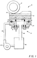
- Figure 1 is a diagrammatic view, partially in section, of a preferred embodiment of a print head with a cooling system.
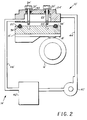
- Figure 2 is diagrammatic view similar to Figure 1, but illustrating another preferred embodiment.
- a thermal printer 10 includes a printing platen 12, and a cooling system 14 for maintaining the temperature of the thermal print head 16 within a preselected temperature range. As illustrated, the thermal print head 16 moves upward to make printing contact with the platen 12.
- the print head 16 has a thermal dye transfer portion 18 and a rear surface 20 with at least one, and preferably two or more, threaded openings 22 in the rear surface 20.
- the cooling system 14 includes a bracket 24 with an opening defining a well or open reservoir 26 for receiving a cooling fluid.
- the bracket 24 has openings 28 equal in number to the number of threaded openings 22 in the rear surface 20.
- the openings 28 open into the reservoir 26.
- Each opening 28 has an annular recess 30 to receive an O-ring 32.
- the bracket openings 28, annular openings 30 and threaded openings 22 comprise a means for attaching the bracket 24 to the print head 16 so that the rear surface 20 of the print head 16 closes the reservoir 26.
- the attaching means includes a bolt 34 insertable through a bracket opening 28 and O-ring 32 to engage the threaded opening 22 to detachably attach the bracket 24 and print head 16.
- the bracket 24 preferably has an annular groove 36 lying outside of the reservoir 26 that is fitted with a gasket, such as O-ring 38, to prevent the cooling fluid from leaking through the interface of the print head 16 and bracket 24.
- a gasket such as O-ring 38
- the means for supplying cooling fluid to the reservoir 26 and bringing the cooling fluid into contact with the rear surface 20 of the print head 16 to effect cooling thereof includes a pump 40.
- the pump 40 delivers cooling fluid, preferably from a coolant reservoir 42, to the bracket reservoir 26 through inlet tube 44.
- the pump 40 delivers cooling fluid through the inlet tube 44 at a rate sufficient to cause the cooling fluid to contact the rear surface 20.
- Spent cooling fluid is removed from the reservoir 26 through outlet tube 46. Because the outlet 46 is at the lowest elevation, the force of gravity is sufficient to cause the cooling fluid to exit the reservoir 26 through the outlet tube 46.
- FIG. 2 another preferred embodiment is illustrated wherein the thermal print head 16' moves downward to make printing contact with the platen 12'.
- the pump 40' delivers cooling fluid through the inlet tube 44', and the force of gravity is sufficient to cause the cooling fluid to contact the rear surface 20' to effect cooling.
- Spent cooling fluid is removed from the reservoir 26' through outlet tube 46'. Because the outlet 46' is at the lowest elevation, the force of gravity is sufficient to cause the cooling fluid to exit the reservoir 26' through the outlet tube 46'. It may be preferable in some instances to have the O-ring 40' in the bracket 24' instead of the rear surface 20'. In that case, a small amount of cooling fluid may remain in the cavity 26' and not gravity drain.
- the gasket disposed between the print head and bracket prevents leaks.
- the print head and bracket are attached by bolts or screws that pass through O-rings in the bracket and screw into tapped holes formed in the rear surface of the print head.
- the coolant drain is positioned below the reservoir so that the cavity is self-draining.
- a pump drives the fluid into the cooling cavity during normal operation. The restriction of the return line compared to the flow rate of the pump is sufficient to achieve this effect. When the pump is turned off, the fluid drains out of the reservoir.
- the print head is oriented with the printing side up. Replacement occurs by turning off the pump to drain the cavity. The fastening bolts are removed and the bracket and printing head are separated The printing head and reservoir may be a little damp, but the loss of fluid will be minimal. Alternatively, the printing head is inverted so that the printing surface is facing downward. The reservoir drain is located close to the interface between the bracket and printing head to drain a maximum quantity of coolant during printing head replacement cycles.
- cooling system for a thermal print head that eliminates the thin layer of metal that typically separates the coolant from the rear surface of the print head.
- the cooling fluid flows directly against the rear surface of the print head. Because the rear surface of the print head transfers heat to the moving coolant fluid instead of the static metal, heat transfer is improved and the running temperature of the print head is reduced.
- the cooling fluid itself is used to establish intimate contact with the surface to be cooled.
- the cooling system is a simple apparatus that cools the print head by having the cooling fluid directly contact the heat producing portion of the print head.
Landscapes
- Electronic Switches (AREA)
- Accessory Devices And Overall Control Thereof (AREA)
Description
- The present invention relates generally to thermal printing, and, more particularly, to a cooling system for a thermal print head.
- In a typical thermal printer, a thermal printing head is used to supply the heat to cause the transfer of dye from a dye bearing donor web to a dye receiver medium. The heating elements are controlled to transfer a variable amount of dye to the receiver. It is desirable to print at the highest speed possible while maintaining control over dye deposition. The typical time required to print a single line has decreased from over thirty milliseconds to about five milliseconds. As the speed has increased, the effective power delivered to the head has steadily increased. The higher amounts of power delivered to the head can affect the temperature of the head which will vary the amount of dye deposited. Accordingly, it will be appreciated that it would be highly desirable to maintain the print head at a constant temperature for consistent printing results.
- Several methods have been used to control the print head temperature. U.S. Patent No. 4,496,824, which issued January 29, 1985 to Kawai et el., discloses a system that uses the head itself to raise the head temperature, and a fan to prevent overheating. U.S. Patent No. 4,797,837 which issued January 10, 1989 to R. M. Brooks, discloses a thermo-electric heater/cooler to control the temperature of the thermal head. U.S. Patent No. 4,968,160, which issued November 6, 1990 to Y. Ishizuka, discloses a heat pump to control the temperature of a thermal head. The temperature controlling fluid is contained in a closed loop with a layer of material between the head and the fluid. Accordingly, it will be appreciated that it would be highly desirable to have a simple apparatus to cool the print head wherein the cooling fluid directly contacts the heat producing portion of the print head.
- US Patent No. 5,017,941 discloses a thermal ink jet printer having a printhead with a passageway therein for the circulation of a cooling fluid therethrough. The passageway is parallel and closely adjacent the array of bubble generating heating elements. When the printhead is composed of mated silicon channel and heater plates, the passageway is formed in one embodiment by forming a groove in the heater plate surface opposite the one containing the heating elements and addressing electrodes followed by the mating of a silicon sealing plate having inlet and outlet openings etched therein. Tubes for circulating a cooling fluid, such as ink, are sealingly attached to the inlet and outlet openings. In an alternative embodiment, the groove may be formed in the sealing plate or in both the sealing plate and the printhead heater plate. In another embodiment, the passageway for the cooling fluid is provided by etching a channel in a thick film layer deposited on the heater plate surface opposite the one with the heating elements. The circulated cooling fluid prevents printhead temperature fluctuations during the printing operation.
- The present invention is directed to overcoming one or more of the problems set forth above. In accordance with the present invention a cooling system for a thermal printer as set forth in claim 1 is provided. Preferred embodiments of the invention are disclosed in the dependent claims. Briefly summarized, according to one aspect of the invention, a cooling system for a thermal print head that has a thermal dye transfer portion and a rear surface includes a bracket defining an open reservoir, and means for attaching the bracket to the print head so that the rear surface closes the reservoir. Cooling fluid is pumped into the reservoir and brought into contact with the rear surface to effect cooling of the print head.
- The bracket is removably attached using bolts with o-rings, and a sealing gasket interposed between the bracket and print head. The print head is easily removed for repair or replacement with minimal loss of cooling fluid.
- These and other aspects, objects, features and advantages of the present invention will be more clearly understood and appreciated from a review of the following detailed description of the preferred embodiments and appended claims, and by reference to the accompanying drawings.
- Figure 1 is a diagrammatic view, partially in section, of a preferred embodiment of a print head with a cooling system.
- Figure 2 is diagrammatic view similar to Figure 1, but illustrating another preferred embodiment.
- Referring to Figure 1, a
thermal printer 10 includes aprinting platen 12, and acooling system 14 for maintaining the temperature of thethermal print head 16 within a preselected temperature range. As illustrated, thethermal print head 16 moves upward to make printing contact with theplaten 12. Theprint head 16 has a thermaldye transfer portion 18 and arear surface 20 with at least one, and preferably two or more, threadedopenings 22 in therear surface 20. - The
cooling system 14 includes abracket 24 with an opening defining a well oropen reservoir 26 for receiving a cooling fluid. Thebracket 24 hasopenings 28 equal in number to the number of threadedopenings 22 in therear surface 20. Theopenings 28 open into thereservoir 26. Each opening 28 has anannular recess 30 to receive an O-ring 32. The bracket openings 28,annular openings 30 and threadedopenings 22 comprise a means for attaching thebracket 24 to theprint head 16 so that therear surface 20 of theprint head 16 closes thereservoir 26. The attaching means includes abolt 34 insertable through a bracket opening 28 and O-ring 32 to engage the threadedopening 22 to detachably attach thebracket 24 and printhead 16. - The
bracket 24 preferably has anannular groove 36 lying outside of thereservoir 26 that is fitted with a gasket, such as O-ring 38, to prevent the cooling fluid from leaking through the interface of theprint head 16 andbracket 24. - The means for supplying cooling fluid to the
reservoir 26 and bringing the cooling fluid into contact with therear surface 20 of theprint head 16 to effect cooling thereof includes apump 40. Thepump 40 delivers cooling fluid, preferably from acoolant reservoir 42, to thebracket reservoir 26 throughinlet tube 44. Thepump 40 delivers cooling fluid through theinlet tube 44 at a rate sufficient to cause the cooling fluid to contact therear surface 20. - Spent cooling fluid is removed from the
reservoir 26 throughoutlet tube 46. Because theoutlet 46 is at the lowest elevation, the force of gravity is sufficient to cause the cooling fluid to exit thereservoir 26 through theoutlet tube 46. - Referring to Figure 2, another preferred embodiment is illustrated wherein the thermal print head 16' moves downward to make printing contact with the platen 12'. The pump 40' delivers cooling fluid through the inlet tube 44', and the force of gravity is sufficient to cause the cooling fluid to contact the
rear surface 20' to effect cooling. Spent cooling fluid is removed from the reservoir 26' through outlet tube 46'. Because the outlet 46' is at the lowest elevation, the force of gravity is sufficient to cause the cooling fluid to exit the reservoir 26' through the outlet tube 46'. It may be preferable in some instances to have the O-ring 40' in the bracket 24' instead of therear surface 20'. In that case, a small amount of cooling fluid may remain in the cavity 26' and not gravity drain. - Operation of the present invention is believed to be apparent from the foregoing description, but a few words will be added for emphasis. The gasket disposed between the print head and bracket prevents leaks. The print head and bracket are attached by bolts or screws that pass through O-rings in the bracket and screw into tapped holes formed in the rear surface of the print head. The coolant drain is positioned below the reservoir so that the cavity is self-draining. A pump drives the fluid into the cooling cavity during normal operation. The restriction of the return line compared to the flow rate of the pump is sufficient to achieve this effect. When the pump is turned off, the fluid drains out of the reservoir.
- Preferably, the print head is oriented with the printing side up. Replacement occurs by turning off the pump to drain the cavity. The fastening bolts are removed and the bracket and printing head are separated The printing head and reservoir may be a little damp, but the loss of fluid will be minimal. Alternatively, the printing head is inverted so that the printing surface is facing downward. The reservoir drain is located close to the interface between the bracket and printing head to drain a maximum quantity of coolant during printing head replacement cycles.
- While the invention has been described with particular reference to the preferred embodiments, it will be understood by those skilled in the art that various changes may be made and equivalents may be substituted for elements of the preferred embodiment without departing from the invention. For example, a blast of air can be directed through the reservoir after draining to remove more of the coolant, or additional electronically controlled valves and pumps can be used to effect more complete or faster draining. In addition, many modifications may be made to adapt a particular situation and material to a teaching of the invention without departing from the essential teachings of the present invention.
- It can now be appreciated that there has been described a cooling system for a thermal print head that eliminates the thin layer of metal that typically separates the coolant from the rear surface of the print head. With the present invention, the cooling fluid flows directly against the rear surface of the print head. Because the rear surface of the print head transfers heat to the moving coolant fluid instead of the static metal, heat transfer is improved and the running temperature of the print head is reduced. The cooling fluid itself is used to establish intimate contact with the surface to be cooled.
- It can also be appreciated that there has been described a cooling system for maintaining the print head at a constant temperature for consistent printing results. The cooling system is a simple apparatus that cools the print head by having the cooling fluid directly contact the heat producing portion of the print head.
- As is evident from the foregoing description, certain aspects of the invention are not limited to the particular details of the examples illustrated, and it is therefore contemplated that other modifications and applications will occur to those skilled in the art. For example, self-siphoning and serpentine passages can be added to the coolant flow route to improve control over the fluid between the states of having a head mounted and not mounted. Various sensing means can be used to determine the presence or absence of the printing head, flow states and fluid levels at different points in the flow path to improve the management of the cooling fluids. It is accordingly intended that the claims shall cover all such modifications and applications.
Claims (7)
- A cooling system (14) for a thermal printer (10), comprising:a thermal print head (16) having a rear surface (20);a bracket (24) defining a reservoir (26);pump means (40) for supplying cooling fluid to said reservoir (26) and bringing said cooling fluid into intimate contact with said rear surface (20) of said print head (16) to effect cooling thereof; anda gasket (38) interposed between said bracket (24) and said rear surface (20) of said print head (16) in sealing engagement to retain said cooling fluid.
- A cooling system, as set forth in claim 1, comprising:said bracket (24) having an opening with an annular recess and forming an entrance to said reservoir ;an o-ring (32) positioned in said annular recess;a bolt (34) insertable through said bracket opening and o-ring to engage a threaded opening in said rear surface (20) to seal said entrance and to removably attach said bracket and print head so that said rear surface covers and closes said reservoir opening;
anda gravity fed outlet for draining cooling fluid from said reservoir (26) so that said cooling fluid does not interfere with detaching said reservoir and print head to expose said reservoir. - A cooling system, as set forth in claim 1 or 2, wherein one of said bracket (24) and said rear surface (20) of said print head defines an annular groove (36) and said gasket is an o-ring positioned in said annular groove.
- A cooling system, as set forth in any of claims 1-3, wherein said bracket (24) is at a lower elevation than said rear surface of said print head and said pump means delivers cooling fluid at a rate sufficient to completely fill said reservoir (26) and contact said rear surface to effect cooling.
- A cooling system, as set forth in any of claims 1-3, wherein said bracket (24) is at a lower elevation than said rear surface of said print head and said pump means delivers cooling fluid at a rate sufficient to cause said cooling fluid to contact said rear surface of said print head to effect cooling.
- A cooling system, as set forth in any of claims 1-3, wherein said bracket (24) is at a lower elevation than said rear surface of said print head and said pump means for supplying cooling fluid to said reservoir (26) incudes an inlet positioned at a lower elevation than said rear surface of said print head.
- A cooling system as set forth in any of claims 1-3 wherein said bracket (24) is at a higher elevation than said rear surface of said print head.
Applications Claiming Priority (2)
| Application Number | Priority Date | Filing Date | Title |
|---|---|---|---|
| US894687 | 1992-06-05 | ||
| US07/894,687 US5211493A (en) | 1992-06-05 | 1992-06-05 | Cooling system for a thermal printing head |
Publications (3)
| Publication Number | Publication Date |
|---|---|
| EP0573062A2 EP0573062A2 (en) | 1993-12-08 |
| EP0573062A3 EP0573062A3 (en) | 1994-08-17 |
| EP0573062B1 true EP0573062B1 (en) | 1996-12-04 |
Family
ID=25403406
Family Applications (1)
| Application Number | Title | Priority Date | Filing Date |
|---|---|---|---|
| EP93109026A Expired - Lifetime EP0573062B1 (en) | 1992-06-05 | 1993-06-04 | Cooling system for a thermal printing head |
Country Status (4)
| Country | Link |
|---|---|
| US (1) | US5211493A (en) |
| EP (1) | EP0573062B1 (en) |
| JP (1) | JPH0632025A (en) |
| DE (1) | DE69306309T2 (en) |
Families Citing this family (21)
| Publication number | Priority date | Publication date | Assignee | Title |
|---|---|---|---|---|
| EP0629508B1 (en) * | 1993-06-18 | 1996-10-09 | Xeikon Nv | Temperature controlled LED recording head |
| US5751327A (en) * | 1993-06-18 | 1998-05-12 | Xeikon N.V. | Printer including temperature controlled LED recording heads |
| JP3323664B2 (en) * | 1994-09-09 | 2002-09-09 | キヤノン株式会社 | Printing equipment |
| US5936646A (en) * | 1996-06-28 | 1999-08-10 | Eastman Kodak Company | Image processing equipment with thermally efficient heat dissipating element |
| JP3199638B2 (en) * | 1996-07-05 | 2001-08-20 | ウシオ電機株式会社 | Sheet heating transfer device |
| DE69722318T2 (en) | 1996-07-15 | 2004-02-12 | Canon K.K. | Inkjet printing apparatus |
| AU2641799A (en) * | 1999-02-26 | 2000-09-21 | Nippon Thermostat Co., Ltd. | Cooling device of electronic device |
| US6428156B1 (en) | 1999-11-02 | 2002-08-06 | Hewlett-Packard Company | Ink delivery system and method for controlling fluid pressure therein |
| JP2006321094A (en) * | 2005-05-18 | 2006-11-30 | Alps Electric Co Ltd | Printer |
| WO2008036220A2 (en) * | 2006-09-18 | 2008-03-27 | Zink Imaging, Inc. | Thermal printer with auxiliary heat sink and methods for printing using same |
| US8339542B2 (en) * | 2009-06-26 | 2012-12-25 | 3M Innovative Properties Company | Passive and hybrid daylight-coupled N-stack and collapsible backlights for sunlight viewable displays |
| US8228463B2 (en) * | 2009-11-18 | 2012-07-24 | 3M Innovative Properties Company | Passive daylight-coupled backlight with turning film having prisms with chaos for sunlight viewable displays |
| US8384852B2 (en) | 2010-11-22 | 2013-02-26 | 3M Innovative Properties Company | Hybrid daylight-coupled backlights for sunlight viewable displays |
| EP2822771B1 (en) | 2012-03-09 | 2019-07-17 | R. R. Donnelley & Sons Company | System and method for cleaning inkjet cartridges |
| US8888208B2 (en) | 2012-04-27 | 2014-11-18 | R.R. Donnelley & Sons Company | System and method for removing air from an inkjet cartridge and an ink supply line |
| US9216581B2 (en) | 2013-02-08 | 2015-12-22 | R.R. Donnelley & Sons Company | Apparatus and method for wiping an inkjet cartridge nozzle plate |
| US20160009028A1 (en) * | 2013-02-25 | 2016-01-14 | Blueprinter Aps | Three-dimensional printer |
| WO2017151177A1 (en) | 2016-03-04 | 2017-09-08 | R.R. Donnelley & Sons Company | Printhead maintenance station and method of operating same |
| CN207291314U (en) | 2016-05-09 | 2018-05-01 | R.R.当纳利父子公司 | Ink feeding unit |
| CN109070460A (en) * | 2016-05-12 | 2018-12-21 | 惠普发展公司,有限责任合伙企业 | Ducts that carry cooling air to the printhead |
| US12151488B2 (en) | 2020-02-20 | 2024-11-26 | Control Print Limited | Thermal inkjet printer with integrated cooling |
Family Cites Families (21)
| Publication number | Priority date | Publication date | Assignee | Title |
|---|---|---|---|---|
| JPS5351743A (en) * | 1976-10-21 | 1978-05-11 | Olympus Optical Co Ltd | Heating medium for heat development |
| JPS5722070A (en) * | 1980-07-15 | 1982-02-04 | Oki Electric Ind Co Ltd | Cooling device for printer |
| JPS5780068A (en) * | 1980-11-07 | 1982-05-19 | Hitachi Ltd | Printing apparatus |
| JPS58160169A (en) * | 1982-03-18 | 1983-09-22 | Shinko Electric Co Ltd | Thermal printer |
| US4730665A (en) * | 1983-07-14 | 1988-03-15 | Technology Enterprises Company | Apparatus for cooling high-density integrated circuit packages |
| JPS60122184A (en) * | 1983-12-06 | 1985-06-29 | Citizen Watch Co Ltd | Temperature-controlling method for printing head in impact printer |
| EP0155975B1 (en) * | 1984-03-24 | 1987-10-28 | HONEYWELL BULL ITALIA S.p.A. | Cooling apparatus for dot matrix impact print head |
| JPS6158783A (en) * | 1984-08-31 | 1986-03-26 | Toshiba Corp | Printing apparatus |
| JPS61106270A (en) * | 1984-10-30 | 1986-05-24 | Fuji Xerox Co Ltd | Thermal head |
| JPH0667655B2 (en) * | 1985-10-08 | 1994-08-31 | 株式会社サト− | Thermal recording printer |
| JPS62109673A (en) * | 1985-11-08 | 1987-05-20 | Hitachi Koki Co Ltd | Cooling device for hammer coil |
| EP0234021B1 (en) * | 1986-01-16 | 1991-12-18 | Siemens Aktiengesellschaft | Liquid cooling device for an electric component, in particular semiconductor component |
| US4797837A (en) * | 1986-04-24 | 1989-01-10 | Ncr Canada Ltd. - Ncr Canada Ltee | Method and apparatus for thermal printer temperature control |
| US4841120A (en) * | 1986-09-12 | 1989-06-20 | Sony Corporation | Thermal head |
| JPH065700B2 (en) * | 1987-07-22 | 1994-01-19 | 株式会社日立製作所 | Cooling device for electronic circuit devices |
| JPH01154786A (en) * | 1987-12-11 | 1989-06-16 | Diesel Kiki Co Ltd | Cooler for printing head |
| DE58908295D1 (en) * | 1988-03-07 | 1994-10-13 | Pluss Stauffer Ag | Pigment mixture for the paper industry. |
| JPH02175261A (en) * | 1988-12-28 | 1990-07-06 | Ricoh Co Ltd | Thermal head cooling device |
| JPH02206560A (en) * | 1989-02-03 | 1990-08-16 | Ricoh Co Ltd | Thermal transfer printer device |
| US5053792A (en) * | 1989-08-03 | 1991-10-01 | Mitsubishi Denki K.K. | Device for cooling thermal head |
| US5017941A (en) * | 1989-11-06 | 1991-05-21 | Xerox Corporation | Thermal ink jet printhead with recirculating cooling system |
-
1992
- 1992-06-05 US US07/894,687 patent/US5211493A/en not_active Expired - Fee Related
-
1993
- 1993-06-03 JP JP5133032A patent/JPH0632025A/en active Pending
- 1993-06-04 DE DE69306309T patent/DE69306309T2/en not_active Expired - Fee Related
- 1993-06-04 EP EP93109026A patent/EP0573062B1/en not_active Expired - Lifetime
Also Published As
| Publication number | Publication date |
|---|---|
| DE69306309T2 (en) | 1997-06-19 |
| DE69306309D1 (en) | 1997-01-16 |
| EP0573062A3 (en) | 1994-08-17 |
| EP0573062A2 (en) | 1993-12-08 |
| JPH0632025A (en) | 1994-02-08 |
| US5211493A (en) | 1993-05-18 |
Similar Documents
| Publication | Publication Date | Title |
|---|---|---|
| US5211493A (en) | Cooling system for a thermal printing head | |
| EP0715960B1 (en) | Liquid ejection recording head | |
| US5489925A (en) | Ink jet printing system | |
| US5291215A (en) | Ink jet recording apparatus with a thermally stable ink jet recording head | |
| US8292396B2 (en) | Image forming apparatus which adjusts ink temperature | |
| US20080055378A1 (en) | Fluid Supply Method and Apparatus | |
| US20110128335A1 (en) | Circulating fluid for fluid droplet ejecting | |
| CA2103410A1 (en) | Ink-cooled thermal ink jet printhead | |
| EP0870622A1 (en) | Ink jet printer with improved printhead cooling system | |
| WO2023103488A1 (en) | Secondary ink cartridge for inkjet printer | |
| US5206978A (en) | Hydrostatic roll for use in calenders | |
| JP2010023342A (en) | Liquid discharge apparatus | |
| JP3327726B2 (en) | Ink jet recording device | |
| JP2008224176A (en) | Heat exchanger and image forming apparatus having the same | |
| WO2023098454A1 (en) | Liquid cooling structure and electronic device | |
| JP2012066470A (en) | Inkjet printer | |
| KR200261549Y1 (en) | Heat exchanger for hydraulic system | |
| JP7413332B2 (en) | Liquid ejection head and liquid ejection device | |
| JPH02206560A (en) | Thermal transfer printer device | |
| WO2004037540A2 (en) | Digital printing apparatus | |
| US11718092B2 (en) | Recording apparatus | |
| US20250353311A1 (en) | Manifold for an inkjet printer | |
| KR19980065203A (en) | Plate Cooling Line for Semiconductor High Density Plasma-Chemical Vapor Deposition (HDP-CVD) | |
| TW202536319A (en) | Water block pressure regulation structure | |
| JPH07113503B2 (en) | Expansion tank for cooling water circulation system |
Legal Events
| Date | Code | Title | Description |
|---|---|---|---|
| PUAI | Public reference made under article 153(3) epc to a published international application that has entered the european phase |
Free format text: ORIGINAL CODE: 0009012 |
|
| AK | Designated contracting states |
Kind code of ref document: A2 Designated state(s): DE FR GB |
|
| PUAL | Search report despatched |
Free format text: ORIGINAL CODE: 0009013 |
|
| AK | Designated contracting states |
Kind code of ref document: A3 Designated state(s): DE FR GB |
|
| 17P | Request for examination filed |
Effective date: 19941230 |
|
| 17Q | First examination report despatched |
Effective date: 19950425 |
|
| GRAG | Despatch of communication of intention to grant |
Free format text: ORIGINAL CODE: EPIDOS AGRA |
|
| GRAH | Despatch of communication of intention to grant a patent |
Free format text: ORIGINAL CODE: EPIDOS IGRA |
|
| GRAH | Despatch of communication of intention to grant a patent |
Free format text: ORIGINAL CODE: EPIDOS IGRA |
|
| GRAA | (expected) grant |
Free format text: ORIGINAL CODE: 0009210 |
|
| AK | Designated contracting states |
Kind code of ref document: B1 Designated state(s): DE FR GB |
|
| REF | Corresponds to: |
Ref document number: 69306309 Country of ref document: DE Date of ref document: 19970116 |
|
| ET | Fr: translation filed | ||
| ET | Fr: translation filed |
Free format text: CORRECTIONS |
|
| PLBE | No opposition filed within time limit |
Free format text: ORIGINAL CODE: 0009261 |
|
| STAA | Information on the status of an ep patent application or granted ep patent |
Free format text: STATUS: NO OPPOSITION FILED WITHIN TIME LIMIT |
|
| 26N | No opposition filed | ||
| PGFP | Annual fee paid to national office [announced via postgrant information from national office to epo] |
Ref country code: GB Payment date: 19980505 Year of fee payment: 6 |
|
| PGFP | Annual fee paid to national office [announced via postgrant information from national office to epo] |
Ref country code: FR Payment date: 19980603 Year of fee payment: 6 |
|
| PGFP | Annual fee paid to national office [announced via postgrant information from national office to epo] |
Ref country code: DE Payment date: 19980625 Year of fee payment: 6 |
|
| PG25 | Lapsed in a contracting state [announced via postgrant information from national office to epo] |
Ref country code: GB Free format text: LAPSE BECAUSE OF NON-PAYMENT OF DUE FEES Effective date: 19990604 |
|
| PG25 | Lapsed in a contracting state [announced via postgrant information from national office to epo] |
Ref country code: FR Free format text: THE PATENT HAS BEEN ANNULLED BY A DECISION OF A NATIONAL AUTHORITY Effective date: 19990630 |
|
| GBPC | Gb: european patent ceased through non-payment of renewal fee |
Effective date: 19990604 |
|
| PG25 | Lapsed in a contracting state [announced via postgrant information from national office to epo] |
Ref country code: DE Free format text: LAPSE BECAUSE OF NON-PAYMENT OF DUE FEES Effective date: 20000503 |
|
| REG | Reference to a national code |
Ref country code: FR Ref legal event code: ST |