EP0572164B1 - Method and apparatus for spatially resolved modulated differential analysis - Google Patents
Method and apparatus for spatially resolved modulated differential analysis Download PDFInfo
- Publication number
- EP0572164B1 EP0572164B1 EP93303879A EP93303879A EP0572164B1 EP 0572164 B1 EP0572164 B1 EP 0572164B1 EP 93303879 A EP93303879 A EP 93303879A EP 93303879 A EP93303879 A EP 93303879A EP 0572164 B1 EP0572164 B1 EP 0572164B1
- Authority
- EP
- European Patent Office
- Prior art keywords
- sample
- temperature
- probe
- modulation
- physical parameter
- Prior art date
- Legal status (The legal status is an assumption and is not a legal conclusion. Google has not performed a legal analysis and makes no representation as to the accuracy of the status listed.)
- Expired - Lifetime
Links
- 238000000034 method Methods 0.000 title claims description 48
- 238000004458 analytical method Methods 0.000 title claims description 21
- 239000000523 sample Substances 0.000 claims description 210
- 230000007704 transition Effects 0.000 claims description 38
- 230000010355 oscillation Effects 0.000 claims description 22
- 239000000463 material Substances 0.000 claims description 21
- 230000008859 change Effects 0.000 claims description 14
- 238000010438 heat treatment Methods 0.000 claims description 14
- 230000005291 magnetic effect Effects 0.000 claims description 5
- 238000012545 processing Methods 0.000 claims description 4
- 230000001747 exhibiting effect Effects 0.000 claims description 2
- 230000002441 reversible effect Effects 0.000 description 25
- 238000004455 differential thermal analysis Methods 0.000 description 12
- 230000008569 process Effects 0.000 description 9
- 238000000113 differential scanning calorimetry Methods 0.000 description 4
- 229920001971 elastomer Polymers 0.000 description 4
- 238000000386 microscopy Methods 0.000 description 4
- 239000000203 mixture Substances 0.000 description 4
- 229920000642 polymer Polymers 0.000 description 4
- 239000005060 rubber Substances 0.000 description 4
- 239000004593 Epoxy Substances 0.000 description 3
- 238000002844 melting Methods 0.000 description 3
- 230000008018 melting Effects 0.000 description 3
- 238000001565 modulated differential scanning calorimetry Methods 0.000 description 3
- 230000004044 response Effects 0.000 description 3
- 230000035945 sensitivity Effects 0.000 description 3
- 230000009466 transformation Effects 0.000 description 3
- IJGRMHOSHXDMSA-UHFFFAOYSA-N Atomic nitrogen Chemical compound N#N IJGRMHOSHXDMSA-UHFFFAOYSA-N 0.000 description 2
- 238000012512 characterization method Methods 0.000 description 2
- 238000006243 chemical reaction Methods 0.000 description 2
- 238000010586 diagram Methods 0.000 description 2
- 230000009477 glass transition Effects 0.000 description 2
- 238000012615 high-resolution technique Methods 0.000 description 2
- 238000003384 imaging method Methods 0.000 description 2
- 230000002427 irreversible effect Effects 0.000 description 2
- 238000005259 measurement Methods 0.000 description 2
- 238000012544 monitoring process Methods 0.000 description 2
- 230000003287 optical effect Effects 0.000 description 2
- 238000001228 spectrum Methods 0.000 description 2
- 239000000126 substance Substances 0.000 description 2
- 238000002076 thermal analysis method Methods 0.000 description 2
- 239000005062 Polybutadiene Substances 0.000 description 1
- 238000013459 approach Methods 0.000 description 1
- 238000004630 atomic force microscopy Methods 0.000 description 1
- 238000004891 communication Methods 0.000 description 1
- 239000002131 composite material Substances 0.000 description 1
- 238000001816 cooling Methods 0.000 description 1
- 239000002178 crystalline material Substances 0.000 description 1
- 238000013500 data storage Methods 0.000 description 1
- 230000001419 dependent effect Effects 0.000 description 1
- 230000000694 effects Effects 0.000 description 1
- 230000005294 ferromagnetic effect Effects 0.000 description 1
- 239000012530 fluid Substances 0.000 description 1
- 239000008241 heterogeneous mixture Substances 0.000 description 1
- 239000007788 liquid Substances 0.000 description 1
- 239000004973 liquid crystal related substance Substances 0.000 description 1
- 238000012986 modification Methods 0.000 description 1
- 230000004048 modification Effects 0.000 description 1
- 229910052757 nitrogen Inorganic materials 0.000 description 1
- 238000000399 optical microscopy Methods 0.000 description 1
- 230000000737 periodic effect Effects 0.000 description 1
- 230000010287 polarization Effects 0.000 description 1
- 229920002857 polybutadiene Polymers 0.000 description 1
- 238000002360 preparation method Methods 0.000 description 1
- 230000005855 radiation Effects 0.000 description 1
- 238000001953 recrystallisation Methods 0.000 description 1
- 239000012925 reference material Substances 0.000 description 1
- 239000011347 resin Substances 0.000 description 1
- 229920005989 resin Polymers 0.000 description 1
- 238000004621 scanning probe microscopy Methods 0.000 description 1
- 238000004574 scanning tunneling microscopy Methods 0.000 description 1
- 239000004065 semiconductor Substances 0.000 description 1
- 238000004611 spectroscopical analysis Methods 0.000 description 1
- 238000000844 transformation Methods 0.000 description 1
- 238000002834 transmittance Methods 0.000 description 1
- 230000005641 tunneling Effects 0.000 description 1
Images


Classifications
-
- G—PHYSICS
- G01—MEASURING; TESTING
- G01N—INVESTIGATING OR ANALYSING MATERIALS BY DETERMINING THEIR CHEMICAL OR PHYSICAL PROPERTIES
- G01N25/00—Investigating or analyzing materials by the use of thermal means
- G01N25/20—Investigating or analyzing materials by the use of thermal means by investigating the development of heat, i.e. calorimetry, e.g. by measuring specific heat, by measuring thermal conductivity
- G01N25/48—Investigating or analyzing materials by the use of thermal means by investigating the development of heat, i.e. calorimetry, e.g. by measuring specific heat, by measuring thermal conductivity on solution, sorption, or a chemical reaction not involving combustion or catalytic oxidation
- G01N25/4806—Details not adapted to a particular type of sample
- G01N25/4826—Details not adapted to a particular type of sample concerning the heating or cooling arrangements
- G01N25/4833—Details not adapted to a particular type of sample concerning the heating or cooling arrangements specially adapted for temperature scanning
-
- G—PHYSICS
- G01—MEASURING; TESTING
- G01N—INVESTIGATING OR ANALYSING MATERIALS BY DETERMINING THEIR CHEMICAL OR PHYSICAL PROPERTIES
- G01N25/00—Investigating or analyzing materials by the use of thermal means
- G01N25/20—Investigating or analyzing materials by the use of thermal means by investigating the development of heat, i.e. calorimetry, e.g. by measuring specific heat, by measuring thermal conductivity
- G01N25/48—Investigating or analyzing materials by the use of thermal means by investigating the development of heat, i.e. calorimetry, e.g. by measuring specific heat, by measuring thermal conductivity on solution, sorption, or a chemical reaction not involving combustion or catalytic oxidation
- G01N25/4846—Investigating or analyzing materials by the use of thermal means by investigating the development of heat, i.e. calorimetry, e.g. by measuring specific heat, by measuring thermal conductivity on solution, sorption, or a chemical reaction not involving combustion or catalytic oxidation for a motionless, e.g. solid sample
- G01N25/4866—Investigating or analyzing materials by the use of thermal means by investigating the development of heat, i.e. calorimetry, e.g. by measuring specific heat, by measuring thermal conductivity on solution, sorption, or a chemical reaction not involving combustion or catalytic oxidation for a motionless, e.g. solid sample by using a differential method
-
- B—PERFORMING OPERATIONS; TRANSPORTING
- B82—NANOTECHNOLOGY
- B82Y—SPECIFIC USES OR APPLICATIONS OF NANOSTRUCTURES; MEASUREMENT OR ANALYSIS OF NANOSTRUCTURES; MANUFACTURE OR TREATMENT OF NANOSTRUCTURES
- B82Y35/00—Methods or apparatus for measurement or analysis of nanostructures
Definitions
- the present invention relates to spatially resolved analytical techniques for determining the composition, phase, structure, or other properties of a sample of material.
- Thermal analysis techniques generally comprise measuring a physical parameter as a function of the temperature of the sample.
- the sample temperature is strictly controlled throughout the analysis. Whenever the sample undergoes a chemical transformation, a physical transformation, a phase change, or another transition which affects the physical parameter being measured, the changes in that physical parameter may be interpreted to analyze the composition, structure or thermal stability of the sample.
- differential thermal analysis techniques the physical parameter of the sample being measured is compared to that of a reference, as a function of the temperature of the sample. The difference in the physical parameter measured for the sample and that measured for the reference is then recorded.
- the differential thermal analysis technique compensates for the effects of heating rate and ambient conditions that could cause changes in the measured physical parameter of the sample and reference.
- the differential thermal analysis technique can increase the sensitivity of the measurement of the physical parameter by removing large offsets in the value of the physical parameter whenever the precision of the measuring apparatus is limited.
- Proximal-probe techniques such as Scanning Tunneling Microscopy and Atomic Force Microscopy obtain spatially-resolved characterization data by bringing a very small probe very close to the sample surface.
- These techniques are described, for example, in M. Hietschold, P. K. Hansma and A. L. Wiesenhorn, "Scanning-Probe-Microscopy and Spectroscopy in Materials Science,” Microscopy and Analysis , September, 1991, pp. 25-27; and N. F. van Hulst and F. B. Segerink, "Optical Microscopy Beyond the Diffraction Limit," Microscopy and Analysis , January, 1992, pp. 21-23. Companies producing Scanning Tunneling Microscopes include Digital Instruments, Santa Barbara, California; Burleigh Instruments, Fishers, N.Y.; and Struers, Westlake, Ohio.
- High resolution analytical techniques are described in European Patent Application Serial No. 91 309 821.6 (EP-A- 0494492). Those techniques seek to improve the resolution of changes in a characterizing physical parameter by controlling the rate of sample heating during transitions as a function of the rate of change of the physical parameter.
- the high resolution techniques are effective in improving resolution for many transitions.
- they usually reduce the sensitivity of transitions when applied to differential thermal analysis techniques. This is because, for most differential thermal analysis techniques, the magnitude of the differential physical parameter is a direct function of the heating rate. Reducing the heating rate during transitions causes the differential signal to change, which may alter or obscure the true differential signal resulting from the transition event. This obscuring of the physical parameter can reduce the utility of the high resolution techniques when applied to conventional differential thermal analysis techniques.
- EP-A-0448985 describes a method of and apparatus for analysing a material sample by applying a voltage to a probe tip which is moved in close proximity to a surface of the material and detecting a change in capacitance of the material.
- a first object of the present invention is to provide an apparatus and a method for obtaining spatially-resolved characterized images of samples.
- a second object of the present invention is to provide a differential thermal analysis technique which can be used to identify different regions in a sample.
- a third object of the present invention is to provide an imaging method that does not require extensive sample preparation.
- Transition or “Transformation”, as used herein, mean any type of physical or chemical transformation, phase change or structural change in a material.
- “Analyzing”, as used herein with respect to materials, means determining the composition, phase, structure and/or identification of the material.
- Charge differential physical parameter means the dependent differential physical parameter characterizing the sample, such as its heat flow, weight change, or change in dielectric or mechanical properties.
- Charged image as used herein with respect to a sample, means an image of a sample wherein the contrast in the image is caused by changes in the characterizing physical parameter as a function of position on the sample.
- Modulation temperature means the average value of the temperature of the sample during one modulation cycle.
- Modulation value means the average value of the driving variable during one modulation cycle.
- Driving variable means temperature acting as the independent physical parameter, that is capable of being used to drive a material through a transition.
- Rapidly reversible means any portion of a signal, transition, or event which is a direct function of the rate of change of the driving variable.
- the contribution to the heat flow signal in DSC attributable to the rate of change of temperature of the sample material is a rapidly reversible transition.
- one of the contributions to the rapidly reversible portion of the heat flow signal is the heat capacity of the sample material. Rapidly reversible processes include those processes which are thermodynamically reversible and can occur rapidly relative to the rate of change of the driving variable.
- Non-rapidly reversible means any portion of a signal, transition or event which is a direct function of the value of the driving variable.
- the contribution to the heat flow signal in DSC attributable to the absolute temperature of the sample material is a non-rapidly reversible transition. This might be caused by a chemical or physical change taking place such as recrystallization.
- Non-rapidly reversible processes include those processes which are thermodynamically irreversible, as well as processes which are thermodynamically reversible, but which reverse very slowly relative to the rate of change of the driving variable due to the kinetic limitations of the process.
- Deconvolution means the process of separating the dependence of a characterizing physical parameter on a driving variable into two or more component parts so that the component parts can be utilized or analyzed separately, or compared with each other.
- the dependence of a characterizing physical parameter can be deconvoluted into rapidly reversible and non-rapidly reversible components.
- Signal baseline means that portion of a signal representing the value of a characterizing physical parameter obtained in a range in which there are no transitions or transformations.
- “Sensitivity” of an analytical technique means the degree to which signals associated with transitions can be physically distinguished from the signal baseline in the analytical data produced by the technique. This quality of the analytical technique is most critical when the value of the driving variable is changing very slowly.
- Resolution of an analytical technique means the degree to which signals associated with different transitions can be physically separated in the analytical data produced by the technique. This quality of the analytical technique is most critical when multiple transitions occur at closely spaced values of the driving variable.
- the present invention provides a spatially-resolved modulated differential analysis apparatus comprising:
- the present invention provides a method of analyzing a sample comprising:
- differential scanning calorimetry As the prototypical differential analytical technique.
- the present invention may be used with any appropriate differential analytical technique, including Pressure Differential Scanning Calorimetry (PDSC), Differential Thermal Analysis (DTA), Pressure Differential Thermal Analysis (PDTA), Differential Photocalorimetry (DPC), and Pressure Differential Photocalorimetry (PDPC).
- PDSC Pressure Differential Scanning Calorimetry
- DTA Differential Thermal Analysis
- PDTA Pressure Differential Thermal Analysis
- DPC Differential Photocalorimetry
- PDPC Pressure Differential Photocalorimetry
- the present invention as applied to spatially-resolved modulated differential scanning calorimetry, comprises a modulated differential scanning calorimeter, as described in EP-A-0494492, wherein a thermocouple probe is scanned over the surface of the sample in close proximity to the sample, as the temperature of the sample is modulated. As the thermocouple probe is scanned, it detects differences in the temperature of the sample corresponding to the thermal properties of the material.
- the present invention could be practiced with other differential analytical techniques, using temperature sensing, capacitance, magnetic, piezoelectric, optical or acoustic probes, as discussed below.
- the sample includes crystalline regions and amorphous regions
- maximal contrast could be obtained by modulating the temperature of the sample above and below a transitions temperature such as the melting point of the crystalline material.
- a plot of the thermocouples probe's response as a function of sample position would then provide an image delineating the crystalline regions from the amorphous regions.
- the contrast in the image would derive from the different responses of the crystalline and amorphous phases, respectively, to the oscillating temperature.
- the sample temperature is varied at two frequencies, a modulation frequency and an oscillation frequency.
- the oscillation frequency would be selected to be different from the modulation frequency by at least a factor of 3, and preferably by at least a factor of 5.
- the modulation frequency if ⁇ m , the oscillation frequency should be 0.2 ⁇ m or lower, or 5 ⁇ m or higher.
- the oscillation frequency would be lower than the modulation frequency.
- the sample contained regions of a polymer phase having a glass transition temperature T g , the polymer regions would be delineated by oscillating the temperature of the sample above and below T g . The region of the sample changing its response in phase with the oscillation frequency would be identified as the polymer phase having that specific T g .
- the scanning of the probe may involve moving the probe incrementally from one position to another in accordance with a predetermined pattern of such positions or by moving the probe continuously.
- the probe may be held in one position, above a previously delineated domain.
- the domain may be representative of many other domains exhibiting similar contrast in the characterized image.
- the temperature of the sample is then scanned to measure the transition temperature of that domain. The value of the transition temperature could then be used to identify the composition of that domain, and of all similar domains.
- the reference thermocouple in differential scanning calorimetry is generally placed in thermal contact with a separate reference material. However, in spatially-resolved differential scanning calorimetry, the reference thermocouple may be placed in contact with the sample itself, either on the same surface as the scanning thermocouple, or on another surface of the sample.
- FIG. 1a shows a sample 11 and a reference 12, with a thermocouple probe 13 and a reference thermocouple 14 in a furnace 15.
- the position of the thermocouple probe 13 on sample 11 is controlled by positioning means 16.
- Positioning means 16 may be partially outside the furnace, as shown in Figure 1a, or it may be wholly within the furnace.
- the data from thermocouple probe 13 and reference thermocouple 14 is recorded by recording means 17, and stored in storing means 18.
- Storing means 18 could comprise a semiconductor memory, and/or magnetic data storage means such as a floppy disk, a hard drive, or magnetic tape.
- the data could flow from recording means 17 directly to storing means 18, or it could first flow to computer 19, and then to storing means 18.
- storing means 18 could be the hard disk of computer 19.
- Computer 19 is used to enter instructions for temperature controller 21 and positioning means 16.
- Computer 19 is also used to deconvolute and analyze the data.
- the temperature of both sample 11 and reference 12 is modulated at a modulation frequency f m by temperature controller 21.
- the differential temperature measured by thermocouple probe 13 and reference thermocouple 14 is a measure of the difference in the heat flow in the sample to the point below the thermocouple probe, and the heat flow in the reference to the point below the reference thermocouple.
- Thermocouple probe 13 is scanned over the surface of sample 11 by scanning means 16 to provide a spatially-resolved characterized image of the sample.
- Figure 1b shows the present invention implemented using a hot stage 31 instead of a furnace.
- a hot stage is the preferred apparatus for controlling the temperature of the sample and reference.
- the temperature of the hot stage is controlled by temperature controller 21, which is in communication with computer 19.
- Sample 11 and reference 12 could be placed adjacent to each other in a controlled thermal environment, such as in a furnace or on a hot stage.
- the temperature of the sample and reference could be modulated by modulating the temperature of the furnace or oven, or by modulating the flow or the temperature of a fluid passing over the sample and the reference.
- Any periodic modulation waveform could be used, including sinusoidal, square, triangular or sawtooth waveforms.
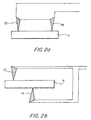
- the reference thermocouple may be placed on the sample itself, i.e. , one position on the sample could be used as the reference for the other positions on the sample, as shown in Figure 2a.
- the reference thermocouple could also be placed in contact with the sample on the opposite side of the probe thermocouple, as shown in Figure 2b.
- Radiant heating means for implementing the second embodiment of the present invention are shown in Figure 1a and Figure 1b.
- the second embodiment comprises two means for periodically varying the temperature of the sample and the reference: furnace 15 or hot stage 31, and radiant heating source 22.
- the temperature of the furnace or hot stage would be controlled by temperature controller 21.
- the radiant heating source would be controlled by radiant source controller 23.
- source controller 23 could impose a sinusoidal modulation onto the power to radiant heating source 22.
- Computer 19 supplies the appropriate input for furnace controller 21 and radiant source controller 23.
- the temperature of the sample would be modulated at, e.g. , ⁇ 1, 2 or 3 °C at a relatively high modulation rate, e.g. , 1-100 Hz by the radiant heating source.
- the sample would also be subjected to a temperature oscillation of, e.g. , ⁇ 5, 10 or 20 °C at a much slower rate, e.g. , at 0.01-1 Hz, by varying the temperature of furnace 15 or hot stage 31.
- a temperature oscillation e.g. , ⁇ 5, 10 or 20 °C at a much slower rate, e.g. , at 0.01-1 Hz, by varying the temperature of furnace 15 or hot stage 31.
- a preferred method for implementing the present invention comprises the following steps:
- STEP 13 may be repeated for each transition temperature, such as at the glass transition for polymer phases, and at the melting point for crystalline phases.
- the transition temperatures may be determined in a preliminary step, in which the characteristics of the entire sample are obtained according to the modulated differential scanning calorimetry technique described in the parent application.
- the sample could be a composite X-Y, consisting of a heterogeneous mixture of a crystalline domain X and an amorphous domain Y.
- the modulation temperature could be set to 500 °C, with a sinusoidal modulation having a modulation amplitude ⁇ 2 °C, and a modulation frequency of 0.05 Hz.
- the thermocouple probe could be moved over a rectangular grid in increments of 200-500 nm. Because the signal from crystalline phase X would be very different from the signal from amorphous phase Y, contrast between the X and Y phases could easily be achieved.
- thermocouple probe may be scanned continuously over the sample in a predetermined pattern, instead of being positioned over predetermined positions as in STEP 5.
- the scanning rate must be selected such that STEPS 1-13 can be performed within a time interval determined by the required spatial resolution.
- the modulation of the sample and reference temperature achieves two goals in a single step: increasing the signal-to-noise ratio of the differential thermal technique, as described in EP-A-0494492, and delineating the different regions of the sample by modulating the temperature of the sample and reference above and below a transition temperature for one phase of the sample material.
- these two goals are achieved using two separate steps at two separate frequencies.
- the two frequencies are designated as the modulation frequency f m and an oscillation frequency f o .
- the temperature of the sample could be modulated at a frequency ranging from 1 to 100 Hz, at an amplitude of ⁇ 1-3 °C, using radiant heating source 22, by controlling the power input to radiant heating source 22 with controller 23.
- the temperature oscillations could be produced by controlling the temperature of hot stage 31, using a sinusoidal waveform with an amplitude of ⁇ 5-10 °C, at a frequency ranging from 0.01 to 0.1 Hz.
- the rubber phase regions could be identified by, for example, selecting the modulation temperature at - 50 °C, the modulation frequency at 2 Hz, and the modulation amplitude at ⁇ 1 °C.
- the oscillation amplitude could be selected at ⁇ 5 °C at a frequency of 0.1 Hz.
- These temperature variations could be achieved by using (1) a cryogenic source such as liquid nitrogen to cool the apparatus down to, e.g.
- the rubber phase will be identifiable because its thermal properties will be changing in phase with the temperature oscillations, whereas the epoxy phase will be comparatively unaffected by the temperature oscillations.
- the epoxy phase could be identified by choosing, for example, a sinusoidal waveform, a modulation temperature of 100 °C, a modulation amplitude of ⁇ 1 °C, a modulation frequency of 5 Hz, an oscillation amplitude of ⁇ 10 °C and an oscillation frequency of 0.2 Hz.
- the DSC spectrum of the entire sample is obtained using modulated differential scanning calorimetry.
- the oscillating modulated DSC technique described as the second preferred embodiment of the present invention is then scanned over the sample successively at each of the transition temperatures identified in the modulated DSC measurement.
- the oscillation amplitude is chosen to cross over one of the transition temperatures in each of the successive scans over the sample.
- a probe is positioned over a region of one phase of the material, as the modulated differential scanning calorimetric technique described in the parent application is applied to obtain a modulated DSC spectrum of that phase.
- a plurality of probes could be used, with one probe positioned over one region of each phase in the sample, or possibly over each region.
- a fourth embodiment of the present invention comprises using an array of probes to obtain differential analysis data simultaneously at a plurality of positions on the sample.
- a linear array of N probes spaced 500 nm apart along the x-axis could be stepped in 500 nm steps to M positions along the y-axis to obtain an array of N ⁇ M data points.
- This array would require the use of N data channels.
- an N ⁇ M area array using N ⁇ M data channels could be used to obtain all the data simultaneously.
- the sample temperature could be scanned over a relatively wide range, e.g. , from cryogenic temperatures to over 1,000 °C. This approach would be most useful when the sample is completely unknown, i.e. , the operator does not know before the analysis which temperature range or transition temperatures to use.
- the fourth embodiment could also be used when the transitions are irreversible.
- frequencies in the megahertz range can be used to probe only material very near the surface.
- the present invention could also be applied using other analytical techniques.
- the present invention could be applied to measure the dielectric properties of a heterogeneous sample having at least two phases using a capacitance probe.
- the temperature of the sample could be modulated above and below a transition in the dielectric properties of one phase of the sample as the capacitance probe is scanned over the surface of the sample.
- the present invention could also be used with an atomic force probe.
- An atomic force probe is scanned over the surface of a heterogeneous sample, containing at least two phases, as the temperature of the sample is modulated. If the two phases have different coefficients of thermal expansion, the atomic force probe will delineate the regions of each phase.
- the present invention could be used with a magnetic sensor, by modulating the temperature of the sample above and below, e.g. , the Curie temperature of a ferromagnetic phase in the material.
- Optical properties of a material such as reflectance, transmittance or polarization state (e.g. , for liquid crystals), could be monitored with a probe such as a laser beam as the sample temperature is modulated above and below a reversible transition in the material.
- thermoacoustic characterization techniques The article "Photoacoustic Microscopy,” by A. Rosencwaig, published in International Laboratory , pages 37-43 (September/October 1979), discusses the use of photoacoustic techniques for microscopy.
- a laser modulated at a high frequency e.g. , at 20 MHz, modulates the temperature of a sample locally ⁇ 1-3 °C about a transition temperature for one phase of the sample.
- the laser beam is scanned over the surface of the sample, as a fixed piezoelectric sensor in direct contact with the surface detects acoustic signals.
- an acoustic microphone may be used to detect the signals.
Landscapes
- Chemical & Material Sciences (AREA)
- Engineering & Computer Science (AREA)
- Chemical Kinetics & Catalysis (AREA)
- Combustion & Propulsion (AREA)
- Physics & Mathematics (AREA)
- Health & Medical Sciences (AREA)
- Life Sciences & Earth Sciences (AREA)
- Analytical Chemistry (AREA)
- Biochemistry (AREA)
- General Health & Medical Sciences (AREA)
- General Physics & Mathematics (AREA)
- Immunology (AREA)
- Pathology (AREA)
- Investigating Or Analyzing Materials Using Thermal Means (AREA)
Description
- The present invention relates to spatially resolved analytical techniques for determining the composition, phase, structure, or other properties of a sample of material.
- Thermal analysis techniques generally comprise measuring a physical parameter as a function of the temperature of the sample. The sample temperature is strictly controlled throughout the analysis. Whenever the sample undergoes a chemical transformation, a physical transformation, a phase change, or another transition which affects the physical parameter being measured, the changes in that physical parameter may be interpreted to analyze the composition, structure or thermal stability of the sample.
- In differential thermal analysis techniques, the physical parameter of the sample being measured is compared to that of a reference, as a function of the temperature of the sample. The difference in the physical parameter measured for the sample and that measured for the reference is then recorded. The differential thermal analysis technique compensates for the effects of heating rate and ambient conditions that could cause changes in the measured physical parameter of the sample and reference. The differential thermal analysis technique can increase the sensitivity of the measurement of the physical parameter by removing large offsets in the value of the physical parameter whenever the precision of the measuring apparatus is limited.
- Proximal-probe techniques such as Scanning Tunneling Microscopy and Atomic Force Microscopy obtain spatially-resolved characterization data by bringing a very small probe very close to the sample surface. These techniques are described, for example, in M. Hietschold, P. K. Hansma and A. L. Wiesenhorn, "Scanning-Probe-Microscopy and Spectroscopy in Materials Science," Microscopy and Analysis, September, 1991, pp. 25-27; and N. F. van Hulst and F. B. Segerink, "Optical Microscopy Beyond the Diffraction Limit," Microscopy and Analysis, January, 1992, pp. 21-23. Companies producing Scanning Tunneling Microscopes include Digital Instruments, Santa Barbara, California; Burleigh Instruments, Fishers, N.Y.; and Struers, Westlake, Ohio.
- C.C. Williams and H.K. Wickramasinghe, "Photothermal Imaging with Sub-100-nm Spatial Resolution," published in Photoacoustic and Photothermal Phenomena, Proceedings, P. Hess and J. Pelzl, eds., Springer Ser. Opt. Sci. v. 58, pp. 364-369 (1988) describes a high resolution thermal microscope using a thermocouple probe.
- High resolution analytical techniques are described in European Patent Application Serial No. 91 309 821.6 (EP-A- 0494492). Those techniques seek to improve the resolution of changes in a characterizing physical parameter by controlling the rate of sample heating during transitions as a function of the rate of change of the physical parameter. When non-differential thermal analysis techniques are used, the high resolution techniques are effective in improving resolution for many transitions. However, they usually reduce the sensitivity of transitions when applied to differential thermal analysis techniques. This is because, for most differential thermal analysis techniques, the magnitude of the differential physical parameter is a direct function of the heating rate. Reducing the heating rate during transitions causes the differential signal to change, which may alter or obscure the true differential signal resulting from the transition event. This obscuring of the physical parameter can reduce the utility of the high resolution techniques when applied to conventional differential thermal analysis techniques.
- Conventional differential thermal analysis techniques are limited in their ability to separate non-reversible events caused by enthalpic processes (chemical or physical) from reversible events such as changes in the heat capacity of the sample. This is because the reversible and non-reversible processes often occur simultaneously, or occur severely overlapped in time and/or temperature.
- In addition, conventional and high resolution thermal analysis techniques cannot distinguish between rapidly reversible and non-rapidly reversible transitions within a single heating or cooling scan of the sample.
- EP-A-0448985 describes a method of and apparatus for analysing a material sample by applying a voltage to a probe tip which is moved in close proximity to a surface of the material and detecting a change in capacitance of the material.
- A first object of the present invention is to provide an apparatus and a method for obtaining spatially-resolved characterized images of samples.
- A second object of the present invention is to provide a differential thermal analysis technique which can be used to identify different regions in a sample.
- A third object of the present invention is to provide an imaging method that does not require extensive sample preparation.
- "Transition" or "Transformation", as used herein, mean any type of physical or chemical transformation, phase change or structural change in a material.
- "Analyzing", as used herein with respect to materials, means determining the composition, phase, structure and/or identification of the material.
- "Characterizing differential physical parameter", as used herein, means the dependent differential physical parameter characterizing the sample, such as its heat flow, weight change, or change in dielectric or mechanical properties.
- "Characterized image", as used herein with respect to a sample, means an image of a sample wherein the contrast in the image is caused by changes in the characterizing physical parameter as a function of position on the sample.
- "Modulation temperature", as used herein, means the average value of the temperature of the sample during one modulation cycle.
- "Modulation value", as used herein, means the average value of the driving variable during one modulation cycle.
- "Driving variable", as used herein, means temperature acting as the independent physical parameter, that is capable of being used to drive a material through a transition.
- "Rapidly reversible", as used herein, means any portion of a signal, transition, or event which is a direct function of the rate of change of the driving variable. For example, the contribution to the heat flow signal in DSC attributable to the rate of change of temperature of the sample material is a rapidly reversible transition. In DSC, for example, one of the contributions to the rapidly reversible portion of the heat flow signal is the heat capacity of the sample material. Rapidly reversible processes include those processes which are thermodynamically reversible and can occur rapidly relative to the rate of change of the driving variable.
- "Non-rapidly reversible", as used herein, means any portion of a signal, transition or event which is a direct function of the value of the driving variable. For example, the contribution to the heat flow signal in DSC attributable to the absolute temperature of the sample material is a non-rapidly reversible transition. This might be caused by a chemical or physical change taking place such as recrystallization. Non-rapidly reversible processes include those processes which are thermodynamically irreversible, as well as processes which are thermodynamically reversible, but which reverse very slowly relative to the rate of change of the driving variable due to the kinetic limitations of the process.
- "Deconvolution", as used herein, means the process of separating the dependence of a characterizing physical parameter on a driving variable into two or more component parts so that the component parts can be utilized or analyzed separately, or compared with each other. For example, the dependence of a characterizing physical parameter can be deconvoluted into rapidly reversible and non-rapidly reversible components.
- "Signal baseline", as used herein, means that portion of a signal representing the value of a characterizing physical parameter obtained in a range in which there are no transitions or transformations.
- "Sensitivity" of an analytical technique, as used herein, means the degree to which signals associated with transitions can be physically distinguished from the signal baseline in the analytical data produced by the technique. This quality of the analytical technique is most critical when the value of the driving variable is changing very slowly.
- "Resolution" of an analytical technique, as used herein, means the degree to which signals associated with different transitions can be physically separated in the analytical data produced by the technique. This quality of the analytical technique is most critical when multiple transitions occur at closely spaced values of the driving variable.
- In one aspect the present invention provides a spatially-resolved modulated differential analysis apparatus comprising:
- (a) means for controlling temperature acting as a driving variable of a sample material and capable of driving the material through a transition
- (b) means for selecting a modulation function, a modulation frequency, a modulation amplitude and a modulation value for modulating the temperature;
- (c) means for modulating the temperature according to the selected modulation function, modulation frequency and modulation amplitude and the modulation value;
- (d) probe means for detecting spatially-resolved differential changes in a characterizing physical parameter caused by the modulated temperature in a localized area of the sample material with respect to a reference;
- (e) means for scanning the probe means across the sample;
- (f) means for recording a signal representative of differential changes in the characterizing physical parameter as a function of the position of the probe on the sample;
- (g) means for storing the signal as data; and
- (h) means for processing the stored data to separate the dependence of the characterizing physical parameter on temperature into at least two component parts such that the component parts can be utilized or analyzed separately to obtain an image of the sample that is characterized according to the differential changes in the characterizing physical parameter as a function of the position of the probe on the sample.
-
- In another aspect the present invention provides a method of analyzing a sample comprising:
- (a) placing a sample in an apparatus comprising means for controlling temperature acting as a driving variable and capable of driving a sample through a transition, a differential probe means, and means for scanning the differential probe means over the sample;
- (b) selecting a modulation function, a modulation frequency, a modulation amplitude and a modulation value for modulating the temperature;
- (c) modulating the temperature according to the selected modulation function, modulation frequency and modulation amplitude and the modulation value
- (d) detecting differential changes in a characterizing physical parameter caused by the modulated temperature in a localized area of the sample material with respect to a reference;
- (e) scanning the probe means across the sample;
- (f) recording a signal representative of differential changes in the characterizing physical parameter as a function of the position of the probe on the sample;
- (g) storing the signal as data; and
- (h) processing the stored data to separate the dependence of the characterizing physical parameter on temperature into at least two component parts such that said parts can be utilized or analyzed separately to obtain an image of the sample that is characterized according to the differential changes in the characterizing physical parameter as a function of the position of the probe on the sample.
-
- The present invention will be described herein using differential scanning calorimetry as the prototypical differential analytical technique. However, the present invention may be used with any appropriate differential analytical technique, including Pressure Differential Scanning Calorimetry (PDSC), Differential Thermal Analysis (DTA), Pressure Differential Thermal Analysis (PDTA), Differential Photocalorimetry (DPC), and Pressure Differential Photocalorimetry (PDPC).
- The present invention, as applied to spatially-resolved modulated differential scanning calorimetry, comprises a modulated differential scanning calorimeter, as described in EP-A-0494492, wherein a thermocouple probe is scanned over the surface of the sample in close proximity to the sample, as the temperature of the sample is modulated. As the thermocouple probe is scanned, it detects differences in the temperature of the sample corresponding to the thermal properties of the material. The present invention could be practiced with other differential analytical techniques, using temperature sensing, capacitance, magnetic, piezoelectric, optical or acoustic probes, as discussed below. If the sample includes crystalline regions and amorphous regions, maximal contrast could be obtained by modulating the temperature of the sample above and below a transitions temperature such as the melting point of the crystalline material. A plot of the thermocouples probe's response as a function of sample position would then provide an image delineating the crystalline regions from the amorphous regions. The contrast in the image would derive from the different responses of the crystalline and amorphous phases, respectively, to the oscillating temperature.
- In another embodiment, the sample temperature is varied at two frequencies, a modulation frequency and an oscillation frequency. The oscillation frequency would be selected to be different from the modulation frequency by at least a factor of 3, and preferably by at least a factor of 5. For example, if the modulation frequency if ƒm , the oscillation frequency should be 0.2ƒm or lower, or 5ƒm or higher. As a general rule, the oscillation frequency would be lower than the modulation frequency. If the sample contained regions of a polymer phase having a glass transition temperature T g , the polymer regions would be delineated by oscillating the temperature of the sample above and below T g . The region of the sample changing its response in phase with the oscillation frequency would be identified as the polymer phase having that specific T g .
- The scanning of the probe may involve moving the probe incrementally from one position to another in accordance with a predetermined pattern of such positions or by moving the probe continuously. The probe may be held in one position, above a previously delineated domain. The domain may be representative of many other domains exhibiting similar contrast in the characterized image. The temperature of the sample is then scanned to measure the transition temperature of that domain. The value of the transition temperature could then be used to identify the composition of that domain, and of all similar domains.
- The reference thermocouple in differential scanning calorimetry is generally placed in thermal contact with a separate reference material. However, in spatially-resolved differential scanning calorimetry, the reference thermocouple may be placed in contact with the sample itself, either on the same surface as the scanning thermocouple, or on another surface of the sample.
- Preferred features of the present invention are described in greater detail in the detailed description of the invention, the appended drawings and the attached claims.
-
- Figure 1a is a schematic diagram of a spatially resolved modulated differential analysis apparatus using a furnace.
- Figure 1b is a schematic diagram of a spatially resolved differential analysis apparatus using a hot stage.
- Figures 2a and 2b are schematic representations showing how the reference thermocouple can be placed on the sample.
-
- The present invention is shown schematically in Figure 1a. Figure 1a shows a
sample 11 and areference 12, with athermocouple probe 13 and areference thermocouple 14 in afurnace 15. The position of thethermocouple probe 13 onsample 11 is controlled by positioning means 16. Positioning means 16 may be partially outside the furnace, as shown in Figure 1a, or it may be wholly within the furnace. The data fromthermocouple probe 13 andreference thermocouple 14 is recorded by recording means 17, and stored in storing means 18. Storing means 18 could comprise a semiconductor memory, and/or magnetic data storage means such as a floppy disk, a hard drive, or magnetic tape. The data could flow from recording means 17 directly to storing means 18, or it could first flow tocomputer 19, and then to storingmeans 18. For example, storing means 18 could be the hard disk ofcomputer 19.Computer 19 is used to enter instructions fortemperature controller 21 and positioning means 16.Computer 19 is also used to deconvolute and analyze the data. Display means 20, e.g., a CRT, a printer or an x-y plotter, is used to display the results of the analysis. The temperature of bothsample 11 andreference 12 is modulated at a modulation frequency fm bytemperature controller 21. The differential temperature measured bythermocouple probe 13 andreference thermocouple 14 is a measure of the difference in the heat flow in the sample to the point below the thermocouple probe, and the heat flow in the reference to the point below the reference thermocouple.Thermocouple probe 13 is scanned over the surface ofsample 11 by scanning means 16 to provide a spatially-resolved characterized image of the sample. - Figure 1b shows the present invention implemented using a
hot stage 31 instead of a furnace. A hot stage is the preferred apparatus for controlling the temperature of the sample and reference. The temperature of the hot stage is controlled bytemperature controller 21, which is in communication withcomputer 19. -
Sample 11 andreference 12 could be placed adjacent to each other in a controlled thermal environment, such as in a furnace or on a hot stage. The temperature of the sample and reference could be modulated by modulating the temperature of the furnace or oven, or by modulating the flow or the temperature of a fluid passing over the sample and the reference. Any periodic modulation waveform could be used, including sinusoidal, square, triangular or sawtooth waveforms. - Alternatively, the reference thermocouple may be placed on the sample itself, i.e., one position on the sample could be used as the reference for the other positions on the sample, as shown in Figure 2a. The reference thermocouple could also be placed in contact with the sample on the opposite side of the probe thermocouple, as shown in Figure 2b.
- Radiant heating means for implementing the second embodiment of the present invention are shown in Figure 1a and Figure 1b. The second embodiment comprises two means for periodically varying the temperature of the sample and the reference:
furnace 15 orhot stage 31, andradiant heating source 22. The temperature of the furnace or hot stage would be controlled bytemperature controller 21. The radiant heating source would be controlled byradiant source controller 23. For example,source controller 23 could impose a sinusoidal modulation onto the power toradiant heating source 22.Computer 19 supplies the appropriate input forfurnace controller 21 andradiant source controller 23. In a typical application, the temperature of the sample would be modulated at, e.g., ± 1, 2 or 3 °C at a relatively high modulation rate, e.g., 1-100 Hz by the radiant heating source. The sample would also be subjected to a temperature oscillation of, e.g., ± 5, 10 or 20 °C at a much slower rate, e.g., at 0.01-1 Hz, by varying the temperature offurnace 15 orhot stage 31. - A preferred method for implementing the present invention comprises the following steps:
- STEP 1.
- Selecting a modulation temperature.
- STEP 2.
- Selecting a modulation frequency.
- STEP 3.
- Selecting a modulation amplitude.
- STEP 4.
- Selecting a pattern of predetermined positions over the sample.
- STEP 5.
- Positioning a thermocouple probe over the sample at an initial predetermined position.
- STEP 6.
- Applying a sinusoidal modulation to the temperature selected in step 1, at the frequency selected in step 2 and at the amplitude selected in Step 3.
- STEP 7.
- Monitoring the signal of the thermocouple probe.
- STEP 8.
- Monitoring the differential heat flow.
- STEP 9.
- Deconvoluting the sample temperature and differential heat flow into rapidly reversible and non-rapidly reversible components of heat flow.
- STEP 10.
- Combining the rapidly reversible and non-rapidly reversible components of heat flow to construct the total heat flow at the underlying heating rate. However, this step is not required for all applications.
-
STEP 11. - Repeating STEPS 6-10 at each of the predetermined positions over the sample.
-
STEP 12. - Calculating one or more two-dimensional images based upon one or more of the heat flows obtained in STEPS 9 and 10. The images may be based upon the rapidly reversible or the non-rapidly reversible components of the heat flow, or upon the total heat flow.
-
STEP 13. - Selecting a new temperature and repeating steps 2-12.
-
STEP 13 may be repeated for each transition temperature, such as at the glass transition for polymer phases, and at the melting point for crystalline phases. The transition temperatures may be determined in a preliminary step, in which the characteristics of the entire sample are obtained according to the modulated differential scanning calorimetry technique described in the parent application. - For example, the sample could be a composite X-Y, consisting of a heterogeneous mixture of a crystalline domain X and an amorphous domain Y. If crystalline domain X had a melting temperature T m at 500 °C, then the modulation temperature could be set to 500 °C, with a sinusoidal modulation having a modulation amplitude ± 2 °C, and a modulation frequency of 0.05 Hz. The thermocouple probe could be moved over a rectangular grid in increments of 200-500 nm. Because the signal from crystalline phase X would be very different from the signal from amorphous phase Y, contrast between the X and Y phases could easily be achieved.
- The procedure of STEPS 1-13 may be modified in several ways. For example, the thermocouple probe may be scanned continuously over the sample in a predetermined pattern, instead of being positioned over predetermined positions as in STEP 5. In that case, the scanning rate must be selected such that STEPS 1-13 can be performed within a time interval determined by the required spatial resolution.
- In the first embodiment of the present invention, the modulation of the sample and reference temperature achieves two goals in a single step: increasing the signal-to-noise ratio of the differential thermal technique, as described in EP-A-0494492, and delineating the different regions of the sample by modulating the temperature of the sample and reference above and below a transition temperature for one phase of the sample material. In the second embodiment of the present invention, these two goals are achieved using two separate steps at two separate frequencies.
- The two frequencies are designated as the modulation frequency fm and an oscillation frequency fo . As an example, the temperature of the sample could be modulated at a frequency ranging from 1 to 100 Hz, at an amplitude of ± 1-3 °C, using
radiant heating source 22, by controlling the power input toradiant heating source 22 withcontroller 23. The temperature oscillations could be produced by controlling the temperature ofhot stage 31, using a sinusoidal waveform with an amplitude of ± 5-10 °C, at a frequency ranging from 0.01 to 0.1 Hz. - For example, a sample of butadiene rubber in a cross-linked expoxy resin could have a transition temperature T g-rubber = - 50 °C for the rubber phase, and a transition temperature T g-epoxy = + 100 °C. The rubber phase regions could be identified by, for example, selecting the modulation temperature at - 50 °C, the modulation frequency at 2 Hz, and the modulation amplitude at ± 1 °C. The oscillation amplitude could be selected at ± 5 °C at a frequency of 0.1 Hz. These temperature variations could be achieved by using (1) a cryogenic source such as liquid nitrogen to cool the apparatus down to, e.g., 78 °K; (2) a hot stage to control the temperature of the sample and reference at temperatures above 78 °K and to provide the temperature oscillation; and (3) a radiation source to provide temperature modulations. The rubber phase will be identifiable because its thermal properties will be changing in phase with the temperature oscillations, whereas the epoxy phase will be comparatively unaffected by the temperature oscillations.
- The epoxy phase could be identified by choosing, for example, a sinusoidal waveform, a modulation temperature of 100 °C, a modulation amplitude of ± 1 °C, a modulation frequency of 5 Hz, an oscillation amplitude of ± 10 °C and an oscillation frequency of 0.2 Hz.
- In an alternative method for applying the second embodiment, the DSC spectrum of the entire sample is obtained using modulated differential scanning calorimetry. The oscillating modulated DSC technique described as the second preferred embodiment of the present invention is then scanned over the sample successively at each of the transition temperatures identified in the modulated DSC measurement. The oscillation amplitude is chosen to cross over one of the transition temperatures in each of the successive scans over the sample.
- In the third preferred embodiment of the present invention, a probe is positioned over a region of one phase of the material, as the modulated differential scanning calorimetric technique described in the parent application is applied to obtain a modulated DSC spectrum of that phase. Alternatively, a plurality of probes could be used, with one probe positioned over one region of each phase in the sample, or possibly over each region.
- A fourth embodiment of the present invention comprises using an array of probes to obtain differential analysis data simultaneously at a plurality of positions on the sample. For example, a linear array of N probes spaced 500 nm apart along the x-axis could be stepped in 500 nm steps to M positions along the y-axis to obtain an array of N × M data points. This array would require the use of N data channels. Alternatively, an N × M area array using N × M data channels could be used to obtain all the data simultaneously. In either the linear or area alternatives of the fourth embodiment, the sample temperature could be scanned over a relatively wide range, e.g., from cryogenic temperatures to over 1,000 °C. This approach would be most useful when the sample is completely unknown, i.e., the operator does not know before the analysis which temperature range or transition temperatures to use. The fourth embodiment could also be used when the transitions are irreversible.
- Higher frequencies allow higher spatial resolution, e.g., resolutions of tens of nanometers. For example, frequencies in the megahertz range can be used to probe only material very near the surface.
- The present invention could also be applied using other analytical techniques. For example, the present invention could be applied to measure the dielectric properties of a heterogeneous sample having at least two phases using a capacitance probe. The temperature of the sample could be modulated above and below a transition in the dielectric properties of one phase of the sample as the capacitance probe is scanned over the surface of the sample.
- The present invention could also be used with an atomic force probe. An atomic force probe is scanned over the surface of a heterogeneous sample, containing at least two phases, as the temperature of the sample is modulated. If the two phases have different coefficients of thermal expansion, the atomic force probe will delineate the regions of each phase. Similarly, the present invention could be used with a magnetic sensor, by modulating the temperature of the sample above and below, e.g., the Curie temperature of a ferromagnetic phase in the material. Optical properties of a material such as reflectance, transmittance or polarization state (e.g., for liquid crystals), could be monitored with a probe such as a laser beam as the sample temperature is modulated above and below a reversible transition in the material.
- The present invention could also be implemented using thermoacoustic characterization techniques. The article "Photoacoustic Microscopy," by A. Rosencwaig, published in International Laboratory, pages 37-43 (September/October 1979), discusses the use of photoacoustic techniques for microscopy. A laser modulated at a high frequency, e.g., at 20 MHz, modulates the temperature of a sample locally ± 1-3 °C about a transition temperature for one phase of the sample. The laser beam is scanned over the surface of the sample, as a fixed piezoelectric sensor in direct contact with the surface detects acoustic signals. Alternatively, an acoustic microphone may be used to detect the signals.
- The foregoing disclosure of embodiments of the present invention has been presented for purposes of illustration and description. It is not intended to be exhaustive or to limit the invention to the precise forms disclosed. Many variations and modifications of the embodiments described herein will be obvious to one of ordinary skill in the art in light of the above disclosure. The scope of the invention is to be defined only by the claims appended hereto.
Claims (21)
- A spatially-resolved modulated differential analysis apparatus comprising:(a) means (21) for controlling temperature acting as a driving variable of a sample material and capable of driving the material through a transition;(b) means (19) for selecting a modulation function, a modulation frequency, a modulation amplitude and a modulation value for modulating the temperature;(c) means (19, 23) for modulating the temperature according to the selected modulation function, modulation frequency and modulation amplitude and the modulation value(d) probe means (13, 14) for detecting spatially-resolved differential changes in a characterizing physical parameter caused by the modulated temperature in a localized area of the sample material with respect to a reference;(e) means (16) for scanning the probe means across the sample;(f) means (17) for recording a signal representative of differential changes in the characterizing physical parameter as a function of the position of the probe on the sample;(g) means (18) for storing the signal as data; and(h) means (19) for processing the stored data to separate the dependence of the characterizing physical parameter on temperature into at least two component parts such that the component parts can be utilized or analyzed separately to obtain an image of the sample that is characterized according to the differential changes in the characterizing physical parameter as a function of the position of the probe on the sample.
- Apparatus according to claim 1, wherein the characterizing physical parameter is heat flow to and from the sample.
- Apparatus according to claim 1 or 2, wherein the means for modulating or varying the temperature comprises radiant heating means or an electric heater element.
- Apparatus according to claim 1, 2 or 3, wherein the reference is a fixed thermal sensor in thermal contact with the sample.
- Apparatus according to claim 4, wherein the probe means is adapted to be scanned across a front surface of the sample and the reference is adapted for making thermal contact with a back surface of the sample.
- Apparatus according to any one of claims 1 to 5, wherein there are a plurality of probe means at a plurality of positions for detecting spatially-resolved differential changes in the temperature of the sample material with respect to the reference and the recording means records calorimetric data from each probe means.
- Apparatus according to claim 6, wherein the plurality of probe means forms a linear array of probe means and further comprising means for scanning the linear array along the sample to a plurality of positions.
- Apparatus according to any one of claims 1 to 5, further comprising means for selecting a pattern of sequential positions on the sample for recording data, wherein the scanning means serves to scan the probe means in steps from one position to the next position so the signal representing the characterizing physical parameter is recorded at each position.
- Apparatus according to any one of claims 1 to 5, wherein scanning means serves to scan the probe means continuously across the sample so the signal representing the characterizing physical parameter is recorded continuously.
- Apparatus according to any one of claims 1 to 9, wherein the or each probe means is a magnetic sensor, a capacitance probe, an atomic force probe, a piezoelectric sensor or an acoustic microphone.
- Apparatus according to any one of claims 1 to 10 and further comprising means for selecting an oscillation cycle with an amplitude and a frequency and means for varying the temperature of the sample in accordance with the oscillation cycle wherein the oscillation frequency and the modulation frequency differ from one another.
- A method of analyzing a sample comprising:(a) placing a sample in an apparatus comprising means (21) for controlling temperature acting as a driving variable and capable of driving a sample through a transition, a differential probe means (13, 14), and means (16) for scanning the differential probe means over the sample;(b) selecting a modulation function, a modulation frequency, a modulation amplitude and a modulation value for modulating the temperature;(c) modulating the temperature according to the selected modulation function, modulation frequency and modulation amplitude and the modulation value;(d) detecting differential changes in a characterizing physical parameter caused by the modulated temperature in a localized area of the sample material with respect to a reference;(e) scanning the probe means across the sample;(f) recording a signal representative of differential changes in the characterizing physical parameter as a function of the position of the probe on the sample;(g) storing the signal as data; and(h) processing the stored data to separate the dependence of the characterizing physical parameter on temperature into at least two component parts such that said component parts can be utilized or analyzed separately to obtain an image of the sample that is characterized according to the differential changes in the characterizing physical parameter as a function of the position of the probe on the sample.
- A method according to claim 12 and further comprising the steps of:(i) selecting a pattern of positions on a sample;(j) placing the probe means over a sample at a first position and detecting and recording the signal at the first position;(k) moving the probe means over the sample to a next position and detecting and recording the signal at the next position;(1) repeating steps (j) and (k) at each of the positions in the pattern of positions selected in step (i), and repeating step (k) at each of the positions in the pattern of positions except for the last position in the pattern.
- A method according to claim 12 and further comprising the steps of(i) selecting a sequence of linear patterns of positions on a sample;(j) placing the probe means over a sample at each of the positions at a first linear pattern and detecting and recording the signal at each position;(k) moving the probe means over the sample to the next linear pattern of positions on the sample and detecting and recording the signal at each position;(1) repeating steps (j) and (k) at each of the linear patterns of positions selected in step (i) and repeating steps (j) and (k) at each of the linear pattern of positions except for the last of the linear pattern of positions.
- A method according to claim 12 and further comprising the steps of selecting a pattern of sequential positions on the sample for recording data and scanning the probe means in incremental steps from one position to the next position, and recording the signal representing the characterizing physical parameter at each position.
- A method according to claim 12 and further comprising the steps of scanning the probe means continuously across the sample, and continuously recording the signal representing the characterizing physical parameter.
- A method according to any one of claims 12 to 15, wherein the data is differential scanning calorimetric data.
- A method according to any one of claims 12 to 16, wherein the sample comprises a first material phase and a second material phase, wherein the first material phase is characterized by a transition temperature, and wherein the modulation amplitude is selected such that the temperature of the sample crosses the transition temperature during the modulation.
- A method according to claim 17 and further comprising the step of identifying regions in the characterized image of the sample that change their appearance in the characterized image at the modulation frequency, as regions of the first material phase.
- A method according to claim 17 and further comprising the step of identifying regions of the sample exhibiting the greatest contest in the characterized image as being regions of the first phase.
- A method according to claims 13 or 14 or any one of claims 15 to 20 when appended to claims 13 or 14 and further comprising m) selecting an oscillation cycle with an oscillation amplitude, the oscillation frequency being different from the modulation frequency and n) also varying the temperature of the sample in accordance with the oscillation cycle wherein step m) is performed before step i) and step n) is performed concurrently with step k) and b).
Applications Claiming Priority (2)
| Application Number | Priority Date | Filing Date | Title |
|---|---|---|---|
| US07/888,933 US5248199A (en) | 1992-03-02 | 1992-05-26 | Method and apparatus for spatially resolved modulated differential analysis |
| US888933 | 1992-05-26 |
Publications (3)
| Publication Number | Publication Date |
|---|---|
| EP0572164A2 EP0572164A2 (en) | 1993-12-01 |
| EP0572164A3 EP0572164A3 (en) | 1996-08-28 |
| EP0572164B1 true EP0572164B1 (en) | 2003-07-23 |
Family
ID=25394195
Family Applications (1)
| Application Number | Title | Priority Date | Filing Date |
|---|---|---|---|
| EP93303879A Expired - Lifetime EP0572164B1 (en) | 1992-05-26 | 1993-05-19 | Method and apparatus for spatially resolved modulated differential analysis |
Country Status (4)
| Country | Link |
|---|---|
| US (1) | US5248199A (en) |
| EP (1) | EP0572164B1 (en) |
| JP (1) | JP2966691B2 (en) |
| DE (1) | DE69333104T2 (en) |
Families Citing this family (32)
| Publication number | Priority date | Publication date | Assignee | Title |
|---|---|---|---|---|
| US5474385A (en) * | 1992-03-02 | 1995-12-12 | Ta Instruments, Inc. | Method and apparatus for parsed dynamic differential analysis |
| US5335993A (en) * | 1992-03-02 | 1994-08-09 | Ta Instruments, Inc. | Method and apparatus for thermal conductivity measurements |
| US5624187A (en) * | 1992-03-02 | 1997-04-29 | Ta Instruments, Inc. | Method and apparatus for gas flow modulated differential scanning calorimetry |
| US5439291C1 (en) * | 1992-03-02 | 2002-04-16 | Ta Instr Inc | Method and apparatus for ac differential thermal analysis |
| US5549387A (en) * | 1994-06-01 | 1996-08-27 | The Perkin-Elmer Corporation | Apparatus and method for differential analysis using real and imaginary signal components |
| AU1279495A (en) * | 1994-12-13 | 1996-07-03 | Consiglio Nazionale Delle Ricerche | Multiharmonic calorimetric spectroscopy |
| JPH08254542A (en) * | 1995-01-09 | 1996-10-01 | Texas Instr Inc <Ti> | Method and equipment to identify sample at nanometer scale and to decide property |
| US6095679A (en) * | 1996-04-22 | 2000-08-01 | Ta Instruments | Method and apparatus for performing localized thermal analysis and sub-surface imaging by scanning thermal microscopy |
| US5813763A (en) * | 1996-10-11 | 1998-09-29 | Microcal Incorporated | Ultrasensitive differential microcalorimeter |
| DE69734153T2 (en) * | 1996-12-31 | 2006-06-22 | Reading, Michael, Ealing | METHOD AND APPARATUS FOR CHEMICAL ANALYSIS FIGURE THROUGH THERMAL GRID MICROSCOPY |
| US6405137B1 (en) | 1996-12-31 | 2002-06-11 | Ta Instruments, Inc. | Method and apparatus for performing chemical analysis using imaging by scanning thermal microscopy |
| US6200022B1 (en) | 1997-04-21 | 2001-03-13 | Ta Instruments, Inc. | Method and apparatus for localized dynamic mechano-thermal analysis with scanning probe microscopy |
| US6099162A (en) * | 1997-10-24 | 2000-08-08 | Hydril Company | Resin cure monitor |
| US6260997B1 (en) * | 1997-10-28 | 2001-07-17 | Michael Claybourn | Method and apparatus for high spatial resolution spectroscopic microscopy |
| US6007240A (en) * | 1998-04-14 | 1999-12-28 | Ta Instruments, Inc. | Method and apparatus for modulated-temperature thermomechanical analysis |
| JP3137605B2 (en) * | 1998-07-14 | 2001-02-26 | セイコーインスツルメンツ株式会社 | Heat flux type differential scanning calorimeter |
| EP1091208B1 (en) * | 1999-09-27 | 2002-10-30 | Mettler-Toledo GmbH | Method and apparatus for thermally analyzing a material |
| WO2001034290A2 (en) | 1999-11-09 | 2001-05-17 | Sri International | Array for generating combinatorial libraries |
| US7033840B1 (en) | 1999-11-09 | 2006-04-25 | Sri International | Reaction calorimeter and differential scanning calorimeter for the high-throughput synthesis, screening and characterization of combinatorial libraries |
| EP1162021B1 (en) * | 2000-06-06 | 2005-02-02 | Matsushita Electric Industrial Co., Ltd. | Method for estimating quality of lead-free solder material and process for flow soldering |
| WO2002040944A1 (en) * | 2000-11-16 | 2002-05-23 | International Business Machines Corporation | Method and apparatus for reading an array of thermal resistance sensors |
| FR2820873A1 (en) * | 2001-07-10 | 2002-08-16 | Commissariat Energie Atomique | Reading of digital data stored by use of a phase change in a recording material using a method based on thermal flux exchange between a sensor and the recording medium so that a single device can be used for reading and writing |
| US20040141541A1 (en) * | 2002-12-02 | 2004-07-22 | John Williams | MEMS-based thermogravimetric analyzer |
| WO2006072261A1 (en) * | 2005-01-04 | 2006-07-13 | Mettler-Toledo Ag | Method and device for analyzing substances |
| US7677088B2 (en) * | 2007-08-28 | 2010-03-16 | Intellectual Properties Partners LLC | Cantilever probe and applications of the same |
| DE102011077005B4 (en) * | 2011-06-06 | 2017-11-16 | Rehm Thermal Systems Gmbh | Plant for heat treatment of substrates and method for acquiring measurement data therein |
| CN103792257B (en) * | 2014-02-12 | 2017-08-22 | 中国纺织科学研究院 | A kind of quantitative analysis method of high temperature resistance filtration material |
| US9702837B2 (en) * | 2014-12-02 | 2017-07-11 | Kuwait Institute For Scientific Research | System for measuring glass transition temperature of a polymer |
| WO2017010884A1 (en) * | 2015-07-16 | 2017-01-19 | Nederlandse Organisatie Voor Toegepast-Natuurwetenschappelijk Onderzoek Tno | Thermal probe for a near-field thermal microscope and method for generating a thermal map |
| CN105572164B (en) * | 2016-02-04 | 2019-07-09 | 华侨大学 | Permanent magnet experimental rig and measurement method for the cooling comparison of mangneto |
| CN105572165B (en) * | 2016-02-04 | 2019-03-12 | 华侨大学 | Test device and measurement method of energized coil for magnetocooling comparison |
| EP4695590A1 (en) | 2023-04-13 | 2026-02-18 | ThermoCap Laboratories Inc. | Concurrent thermal measurements of a plurality of samples |
Family Cites Families (22)
| Publication number | Priority date | Publication date | Assignee | Title |
|---|---|---|---|---|
| US2975629A (en) * | 1958-06-06 | 1961-03-21 | Patent & Licensing Corp | Test equipment for determining temperature change characteristics of materials |
| US3263484A (en) * | 1962-04-04 | 1966-08-02 | Perkin Elmer Corp | Differential microcalorimeter |
| US3271996A (en) * | 1965-11-24 | 1966-09-13 | Paulik Ferenc | Apparatus for thermal analysis |
| US3339398A (en) * | 1964-03-30 | 1967-09-05 | Chevron Res | High sensitivity differential thermal analysis apparatus and method |
| US3360993A (en) * | 1965-08-27 | 1968-01-02 | Air Force Usa | Single thermocouple differentiating method and system |
| US3789662A (en) * | 1971-10-26 | 1974-02-05 | Instrumentation Labor Inc | Calorimetry |
| US4255961A (en) * | 1978-10-17 | 1981-03-17 | University Of Va. Alumni Patents Foundation | Differential calorimeter based on the heat leak principle |
| US4350446A (en) * | 1980-11-03 | 1982-09-21 | E. I. Du Pont De Nemours And Company | Method and apparatus for calorimetric differential thermal analysis |
| DE3529489A1 (en) * | 1985-08-16 | 1987-02-26 | Max Planck Gesellschaft | METHOD AND DEVICE FOR DETERMINING THE HEAT CAPACITY OF A SAMPLE |
| US4838706A (en) * | 1986-03-24 | 1989-06-13 | The Provost, Fellows And Scholars Of The College Of The Holy And Undivided Trinity Of Queen Elizabeth Near Dublin | Thermal analysis |
| US4747698A (en) * | 1986-04-30 | 1988-05-31 | International Business Machines Corp. | Scanning thermal profiler |
| US4690569A (en) * | 1986-05-22 | 1987-09-01 | Qualtronics Corporation | Thermal profile system |
| US4840496A (en) * | 1988-02-23 | 1989-06-20 | The United States Of America As Represented By The Administrator Of The National Aeronautics And Space Administration | Noncontact temperature pattern measuring device |
| JP2896794B2 (en) * | 1988-09-30 | 1999-05-31 | キヤノン株式会社 | Scanning tunnel current detector, scanning tunnel microscope, and recording / reproducing device |
| US4941753A (en) * | 1989-04-07 | 1990-07-17 | International Business Machines Corp. | Absorption microscopy and/or spectroscopy with scanning tunneling microscopy control |
| GB8910566D0 (en) * | 1989-05-08 | 1989-06-21 | Amersham Int Plc | Imaging apparatus and method |
| JP2686653B2 (en) * | 1989-06-05 | 1997-12-08 | キヤノン株式会社 | Relative displacement amount detector |
| GB2233457A (en) * | 1989-06-21 | 1991-01-09 | Schlumberger Technologies Ltd | Temperature reference junction for a multichannel temperature sensing system. |
| US5065103A (en) * | 1990-03-27 | 1991-11-12 | International Business Machines Corporation | Scanning capacitance - voltage microscopy |
| US5060248A (en) * | 1990-06-29 | 1991-10-22 | General Electric Company | Scanning analysis and imaging system with modulated electro-magnetic energy source |
| CA2089392A1 (en) * | 1991-05-29 | 1992-11-30 | Chi Li | Method and apparatus for simultaneous differential scanning calorimetry and microdielectrometry |
| US5224775C2 (en) * | 1992-03-02 | 2002-04-23 | Ta Instr Inc | Method and apparatus for modulated differential analysis |
-
1992
- 1992-05-26 US US07/888,933 patent/US5248199A/en not_active Expired - Lifetime
-
1993
- 1993-05-19 DE DE69333104T patent/DE69333104T2/en not_active Expired - Lifetime
- 1993-05-19 EP EP93303879A patent/EP0572164B1/en not_active Expired - Lifetime
- 1993-05-26 JP JP5124269A patent/JP2966691B2/en not_active Expired - Lifetime
Also Published As
| Publication number | Publication date |
|---|---|
| EP0572164A3 (en) | 1996-08-28 |
| EP0572164A2 (en) | 1993-12-01 |
| DE69333104T2 (en) | 2004-04-22 |
| JPH07286981A (en) | 1995-10-31 |
| JP2966691B2 (en) | 1999-10-25 |
| US5248199A (en) | 1993-09-28 |
| DE69333104D1 (en) | 2003-08-28 |
Similar Documents
| Publication | Publication Date | Title |
|---|---|---|
| US5248199A (en) | Method and apparatus for spatially resolved modulated differential analysis | |
| US6200022B1 (en) | Method and apparatus for localized dynamic mechano-thermal analysis with scanning probe microscopy | |
| CA1318980C (en) | Scanning tunnel-current-detecting device and method for detecting tunnel current and scanning tunnelling microscope and recording/reproducing device using thereof | |
| US5439291A (en) | Method and apparatus for AC Differential thermal analysis | |
| US5196701A (en) | High-resolution detection of material property variations | |
| US7615738B2 (en) | Scanning probe microscope assembly and method for making spectrophotometric, near-field, and scanning probe measurements | |
| KR100961571B1 (en) | Scanning probe microscope | |
| Jaschke et al. | Height calibration of optical lever atomic force microscopes by simple laser interferometry | |
| US4941753A (en) | Absorption microscopy and/or spectroscopy with scanning tunneling microscopy control | |
| EP0834069B1 (en) | Method and apparatus for performing localized thermal analysis and sub-surface imaging by scanning thermal microscopy | |
| EP0587165B1 (en) | Information processing apparatus having multiprobe control circuit | |
| US8177422B2 (en) | Transition temperature microscopy | |
| Tanaka et al. | Scanning nonlinear dielectric microscopy nano-science and technology for next generation high density ferroelectric data storage | |
| US10556793B2 (en) | Thermal measurements using multiple frequency atomic force microscopy | |
| EP0948741B1 (en) | Method and apparatus for high spatial resolution spectroscopic microscopy | |
| EP0383323A1 (en) | Tunneling acoustic microscope | |
| JPH02187944A (en) | Reproducing device | |
| US5466935A (en) | Programmable, scanned-probe microscope system and method | |
| US7401503B2 (en) | Method for analysis through layer-by-layer sample removal using a cantilever probe | |
| Cretin | Scanning near-field thermal and thermoacoustic microscopy: performances and limitations | |
| JPH063397A (en) | Potential distribution measuring device | |
| JPH08315434A (en) | Information processing device | |
| GB2332949A (en) | Method and apparatus for localized mechanothermal analysis combined with scanning probe microscopy | |
| Bhattacharyya et al. | An automated nondestructive characterization system for pyroelectric materials | |
| Pelzl et al. | New developments in thermal wave microscopy |
Legal Events
| Date | Code | Title | Description |
|---|---|---|---|
| PUAI | Public reference made under article 153(3) epc to a published international application that has entered the european phase |
Free format text: ORIGINAL CODE: 0009012 |
|
| AK | Designated contracting states |
Kind code of ref document: A2 Designated state(s): DE GB |
|
| PUAL | Search report despatched |
Free format text: ORIGINAL CODE: 0009013 |
|
| RHK1 | Main classification (correction) |
Ipc: G01N 25/20 |
|
| AK | Designated contracting states |
Kind code of ref document: A3 Designated state(s): DE GB |
|
| 17P | Request for examination filed |
Effective date: 19970211 |
|
| 17Q | First examination report despatched |
Effective date: 20000529 |
|
| GRAH | Despatch of communication of intention to grant a patent |
Free format text: ORIGINAL CODE: EPIDOS IGRA |
|
| GRAH | Despatch of communication of intention to grant a patent |
Free format text: ORIGINAL CODE: EPIDOS IGRA |
|
| GRAA | (expected) grant |
Free format text: ORIGINAL CODE: 0009210 |
|
| AK | Designated contracting states |
Designated state(s): DE GB |
|
| REG | Reference to a national code |
Ref country code: GB Ref legal event code: FG4D |
|
| REF | Corresponds to: |
Ref document number: 69333104 Country of ref document: DE Date of ref document: 20030828 Kind code of ref document: P |
|
| PLBE | No opposition filed within time limit |
Free format text: ORIGINAL CODE: 0009261 |
|
| STAA | Information on the status of an ep patent application or granted ep patent |
Free format text: STATUS: NO OPPOSITION FILED WITHIN TIME LIMIT |
|
| 26N | No opposition filed |
Effective date: 20040426 |
|
| PGFP | Annual fee paid to national office [announced via postgrant information from national office to epo] |
Ref country code: DE Payment date: 20120529 Year of fee payment: 20 |
|
| PGFP | Annual fee paid to national office [announced via postgrant information from national office to epo] |
Ref country code: GB Payment date: 20120525 Year of fee payment: 20 |
|
| REG | Reference to a national code |
Ref country code: DE Ref legal event code: R071 Ref document number: 69333104 Country of ref document: DE |
|
| REG | Reference to a national code |
Ref country code: GB Ref legal event code: PE20 Expiry date: 20130518 |
|
| PG25 | Lapsed in a contracting state [announced via postgrant information from national office to epo] |
Ref country code: DE Free format text: LAPSE BECAUSE OF EXPIRATION OF PROTECTION Effective date: 20130522 Ref country code: GB Free format text: LAPSE BECAUSE OF EXPIRATION OF PROTECTION Effective date: 20130518 |