EP0570450B1 - Centroiding method for photon counting detectors - Google Patents
Centroiding method for photon counting detectors Download PDFInfo
- Publication number
- EP0570450B1 EP0570450B1 EP92904359A EP92904359A EP0570450B1 EP 0570450 B1 EP0570450 B1 EP 0570450B1 EP 92904359 A EP92904359 A EP 92904359A EP 92904359 A EP92904359 A EP 92904359A EP 0570450 B1 EP0570450 B1 EP 0570450B1
- Authority
- EP
- European Patent Office
- Prior art keywords
- channels
- channel
- events
- allocated
- photon
- Prior art date
- Legal status (The legal status is an assumption and is not a legal conclusion. Google has not performed a legal analysis and makes no representation as to the accuracy of the status listed.)
- Expired - Lifetime
Links
Images


Classifications
-
- G—PHYSICS
- G01—MEASURING; TESTING
- G01J—MEASUREMENT OF INTENSITY, VELOCITY, SPECTRAL CONTENT, POLARISATION, PHASE OR PULSE CHARACTERISTICS OF INFRARED, VISIBLE OR ULTRAVIOLET LIGHT; COLORIMETRY; RADIATION PYROMETRY
- G01J1/00—Photometry, e.g. photographic exposure meter
- G01J1/42—Photometry, e.g. photographic exposure meter using electric radiation detectors
-
- H—ELECTRICITY
- H04—ELECTRIC COMMUNICATION TECHNIQUE
- H04N—PICTORIAL COMMUNICATION, e.g. TELEVISION
- H04N25/00—Circuitry of solid-state image sensors [SSIS]; Control thereof
- H04N25/70—SSIS architectures; Circuits associated therewith
- H04N25/76—Addressed sensors, e.g. MOS or CMOS sensors
- H04N25/77—Pixel circuitry, e.g. memories, A/D converters, pixel amplifiers, shared circuits or shared components
- H04N25/772—Pixel circuitry, e.g. memories, A/D converters, pixel amplifiers, shared circuits or shared components comprising A/D, V/T, V/F, I/T or I/F converters
- H04N25/773—Pixel circuitry, e.g. memories, A/D converters, pixel amplifiers, shared circuits or shared components comprising A/D, V/T, V/F, I/T or I/F converters comprising photon counting circuits, e.g. single photon detection [SPD] or single photon avalanche diodes [SPAD]
-
- G—PHYSICS
- G01—MEASURING; TESTING
- G01J—MEASUREMENT OF INTENSITY, VELOCITY, SPECTRAL CONTENT, POLARISATION, PHASE OR PULSE CHARACTERISTICS OF INFRARED, VISIBLE OR ULTRAVIOLET LIGHT; COLORIMETRY; RADIATION PYROMETRY
- G01J1/00—Photometry, e.g. photographic exposure meter
- G01J1/42—Photometry, e.g. photographic exposure meter using electric radiation detectors
- G01J1/44—Electric circuits
- G01J2001/4413—Type
- G01J2001/442—Single-photon detection or photon counting
-
- G—PHYSICS
- G01—MEASURING; TESTING
- G01J—MEASUREMENT OF INTENSITY, VELOCITY, SPECTRAL CONTENT, POLARISATION, PHASE OR PULSE CHARACTERISTICS OF INFRARED, VISIBLE OR ULTRAVIOLET LIGHT; COLORIMETRY; RADIATION PYROMETRY
- G01J1/00—Photometry, e.g. photographic exposure meter
- G01J1/42—Photometry, e.g. photographic exposure meter using electric radiation detectors
- G01J1/44—Electric circuits
- G01J2001/4446—Type of detector
- G01J2001/448—Array [CCD]
Definitions
- This invention relates to a centroiding method for use with photon counting detectors.
- each pixel may be divided into as many as 8 channels along each axis. It should be understood that although the invention is described below in relation to dividing each pixel into 8 channels along each axis, it is equally applicable if the number of channels is more or less than 8.
- Photon counting detectors employing CCD's can be split into two categories, namely where there is lens coupling between the intensifier and the CCD; and where there is fibre optic coupling between the intensifier and CCD.
- the event is noticeably asymmetrical, the direction of the asymmetry being dependent upon the orientation of the CCD with respect to the channel plate. Fitting an error free algorithm to this profile such that each event is accurately centred to 1/8th of a CCD pixel or better would be very complex in hardware and in software would be very time consuming, limiting the dynamic range by introducing a maximum count rate that can be processed. It is an object of the present invention to provide a centroiding technique that overcomes such problems and provides accurate centroiding with low fixed pattern noise.
- centroiding algorithm conventionally used to allocate an event to a channel.
- This algorithm is depicted in Fig. 2.
- the algorithm can be implemented using discrete integrated circuits and this is what is conventionally done. It can in theory be implemented directly as a look-up table. However, there is a physical constraint against this as a 40-bit address word would be required to allow for all combinations of A through to E - in other words 1012 memory locations, as in Fig.3a.
- the present invention employs a look-up table, and it is a novel feature of the preferred embodiment thereof that the problem just described is reduced by calculating M and N in equation 1 discretely in hardware and then feeding these values as the address to the look-up table, the data contained in that address being the result of the division M/N, as in Fig. 3b.
- a method of setting up a photon counting detector to enable it to carry out a centroiding procedure in which a photon event occurring in a given range is allocated to one of a plurality of channels into which the range is divided, the said method comprising the steps of:
- Figure 1a shows a typical photon event which is to be detected
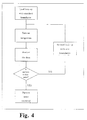
- FIG. 4 is a flow diagram showing a preferred embodiment of the method defined above.
- the Look Up Table (LUT) is initially loaded by the computer with equal boundary positions for all values of M/N as shown in Table 1. An integration is then carried out. The derived M and N for each photon event are used as the address to the LUT.
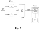
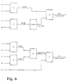
- Figure 6 shows a block diagram of the electronics used to derive the values for M and N. Typically, 74LS238 integrated circuits are used for the adders and a 74LS540 integrated circuit is used for the invert function.) The 3 bit output of the LUT gives the centroid position. This is combined with the Row/Column CCD pixel address to define the Data Acquisition Memory address that is associated with that centroid position.
- the value held at this Memory address is then incremented by 1 to show that a photon event has occurred at that position.
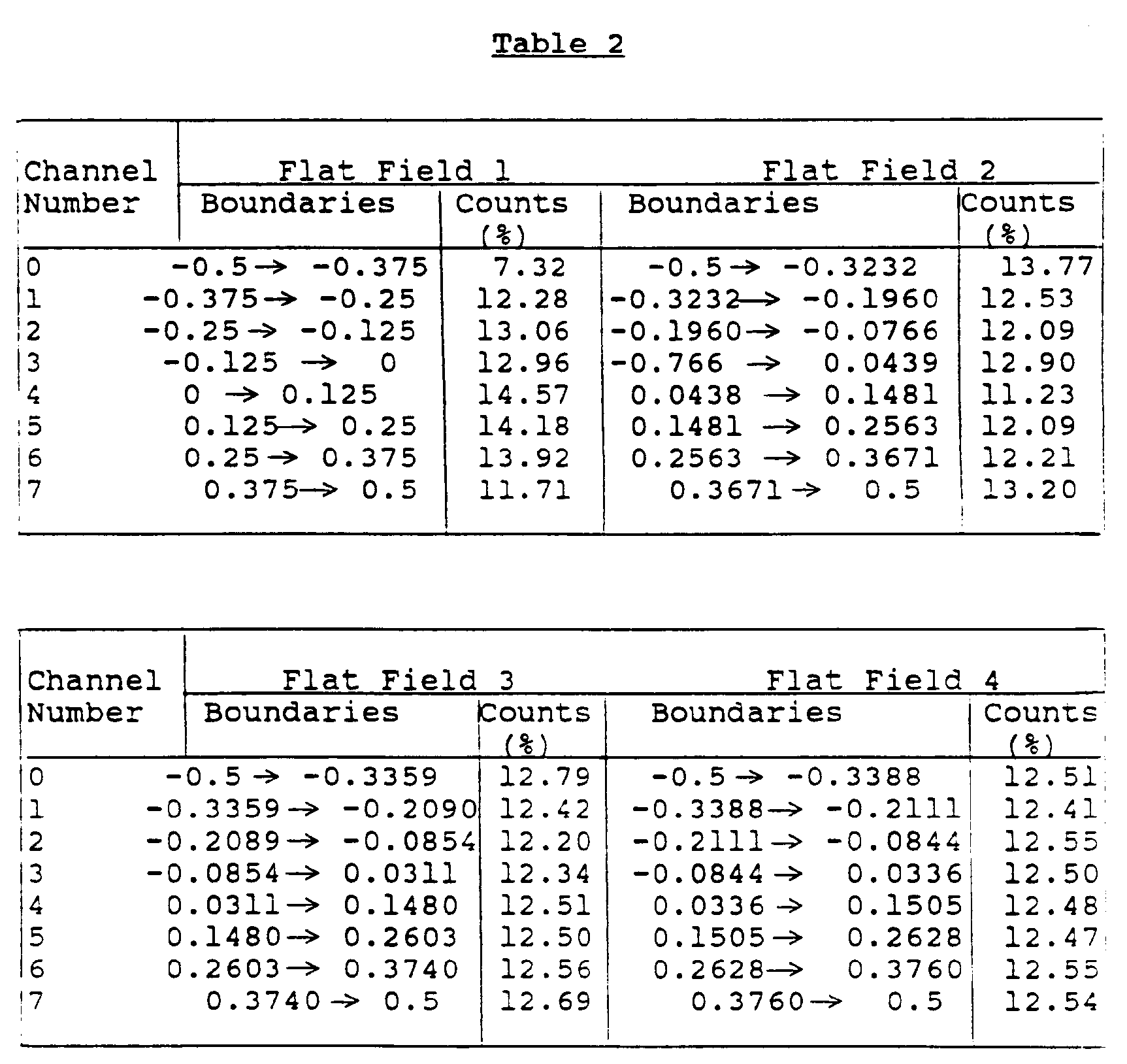
- the computer software analyses the data in the Data Acquisition Memory to find the level of fixed pattern noise, a typical result being shown in Flat Field 1 of Table 2.
- the LUT is then reloaded with new boundary positions, as is typically shown in Flat Field 2 of Table 2, and another integration carried out. This procedure is then repeated until the fixed pattern noise is minimized.
- Fig. 7 shows the result of the initial integration and three iterations of the procedure. Each flat field shows less pattern noise than the previous one, the last having a negligible amount.
- Table 2 below shows boundary values and the percentage of the total counts obtained in each channel for each flat field of Fig. 7.
- the third column shows the percentage of total counts in each channel obtained from having a look-up table loaded with the standard boundary values (column 2). The computer uses these percentage values to work out the new channel boundary values of column 4 which, when loaded into the look-up table, produce the percentages of column 5 on a subsequent flat field, and so on. The range of count values is gradually reduced until it is within that expected from random system noise.
- Fig. 8 shows the power spectra of the first and last flat fields of Fig. 7 and confirms that the pattern noise has been removed.
- the alteration of the boundary positions is done according to a linear distribution of events within a pixel. Although the distribution is known be nonlinear, this does not matter since the algorithm converges quickly, typically requiring only three or four iterations.
- New width Old width + 1/8 (1-(Count in bin)/(Mean count))
- New width W/ ⁇ W, ⁇ W being the summation over all eight channels.
- An important feature of the method is that it can cope with asymmetrical profiles by ensuring that, when the result of the algorithm lies outside the range defined in the look-up, the event is placed in the nearest channel of the adjacent pixel. It does this in hardware using an asymmetry flag. Where the result of M/N is outside of the range -0.5 to +0.5 then this means that the centre of gravity of the event is not in the same pixel as that containing the peak data. If the result is ⁇ -0.5 then the centre of gravity is in the previous pixel, and if >+0.5 then the centre of gravity is in the next pixel, B and D respectively in Figure 2.
- the asymmetry profile flat is a two bit flat that is output by the Look Up Table when the result of M/N is either ⁇ -0.5 (first bit set) or >+0.5 (second bit set) and tells the hardware to take the previous value output by the Look Up Table as the centroid position, if the result of M/N is ⁇ -0.5, or take the following value output by the Look Up Table, if the value of M/N is >+0.5.
- the centroiding is then carried out, not with the peak data pixel at the centre as is normal, but with B or D respectively.
- the method can also be used with 3-pixel algorithms but, so long as an event covers more than three pixels, a 5-pixel algorithm should give more accurate event positions since otherwise information is being lost about the wings of the event. However, it is desirable that the events are as compact as possible since wide events decrease centroiding accuracy and increase coincidence effects.
Landscapes
- Physics & Mathematics (AREA)
- General Physics & Mathematics (AREA)
- Spectroscopy & Molecular Physics (AREA)
- Engineering & Computer Science (AREA)
- Multimedia (AREA)
- Signal Processing (AREA)
- Photometry And Measurement Of Optical Pulse Characteristics (AREA)
- Transforming Light Signals Into Electric Signals (AREA)
- Measurement Of Radiation (AREA)
Abstract
Description
- This invention relates to a centroiding method for use with photon counting detectors.
- Over the past few years a number of photon counting detectors that employ charge-coupled devices (CCDs) for event capture have been developed. These detectors all use interpolative centroiding, at some level, to enhance the resolution of the system, event centres being found with an accuracy as high as 1/8th of a CCD pixel in each of the x and y axes, i.e. to 1/64th of a pixel. This process is referred to as the allocation of an event to a channel. Thus, each pixel may be divided into as many as 8 channels along each axis. It should be understood that although the invention is described below in relation to dividing each pixel into 8 channels along each axis, it is equally applicable if the number of channels is more or less than 8.
- Recent publications (Fordham, J.L.A. and Hook, R.N. 1988, Robinson, L.B., ed., "Instrumentation for Ground-Based Optical Astronomy, Present and Future (Springer-Verlag, New York), p.582; and Dick, J., Jenkins, C. and Ziabicki, J. 1989, PASP, 101, 684) discuss errors associated with the centroiding algorithms and the effect on system fixed pattern noise. In these papers it is assumed that the event profile is a Gaussian, showing the effect of variations in, for example, pulse width, noise, and DC bias on centroiding accuracy. However, when analyzed it is found that events do not have a Gaussian profile and so the approach adopted in those papers is less effective than it would otherwise be.
- Photon counting detectors employing CCD's can be split into two categories, namely where there is lens coupling between the intensifier and the CCD; and where there is fibre optic coupling between the intensifier and CCD.
- For the lens coupled system, distortions are introduced onto the event profile by the lens, where the distortion is dependent upon the radial position of the event with respect to the optical centre. These distortions are due to aberrations within the lens. For this type of detector, where there is no defined pulse shape, a single accurate centroiding algorithm, whether hardware or software generated, cannot be employed. This means that, from the algorithm, there always will be centroiding errors which cause fixed pattern noise similar to that discussed in the above referenced papers. The only way to overcome this is to include a smoothing function within the centroiding circuit.
- For the fibre optically coupled systems, if very localized shears in the coupler are discounted, then the CCD will produce an accurate image of each event generated on the intensifier output phosphor. However, fibre optic coupling is only normally employed on micro-channel plate (MCP) intensifiers, and these give rise to an additional form of distortion due to the bias angle of the channel plates with respect to the output phosphor. This bias angle, typically of 8 degrees, introduces an asymmetrical profile to each event which is constant over the whole active area and can thus be fitted, in principle, by a single algorithm. A typical event is shown in Fig. 1a of the accompanying drawings and a profile of a slice through the centre of this event is shown in Fig.1b.
- The event is noticeably asymmetrical, the direction of the asymmetry being dependent upon the orientation of the CCD with respect to the channel plate. Fitting an error free algorithm to this profile such that each event is accurately centred to 1/8th of a CCD pixel or better would be very complex in hardware and in software would be very time consuming, limiting the dynamic range by introducing a maximum count rate that can be processed. It is an object of the present invention to provide a centroiding technique that overcomes such problems and provides accurate centroiding with low fixed pattern noise.
- Before describing the present invention a description will be given of the centroiding algorithm conventionally used to allocate an event to a channel.
- A typical five pixel centre of gravity-fitting algorithm is of the form:

where M = 2A+B-D-2E, N = A+B+C+D+E, and
A,B,C,D and E are the 8-bit data values in 5 contiguous pixels, C having the highest amplitude. This algorithm is depicted in Fig. 2. - The algorithm can be implemented using discrete integrated circuits and this is what is conventionally done. It can in theory be implemented directly as a look-up table. However, there is a physical constraint against this as a 40-bit address word would be required to allow for all combinations of A through to E - in other words 10¹² memory locations, as in Fig.3a. As is described below, the present invention employs a look-up table, and it is a novel feature of the preferred embodiment thereof that the problem just described is reduced by calculating M and N in equation 1 discretely in hardware and then feeding these values as the address to the look-up table, the data contained in that address being the result of the division M/N, as in Fig. 3b.
- Assuming pixel C had the highest value data, that is, an event was central in the 5 pixels, and assuming events were symmetrical then the result of M/N would always be in the range -0.5 to +0.5, that is ± 1/2 a pixel from the centre of C. The requirement is to split each pixel into 8 separate channels and place the centroid in one of them. Thus eight M/N result ranges can be defined as shown in Table 1 below.

- Allowing for every combination of M and N the lookup table can be programmed as above. If an integration is then started with the system, and data is accumulated on a flat field, the resulting image would look something like the graph (a) in Figure 7, where there could be a large amount of fixed pattern noise with a period of 8 channels or one CCD pixel. This noise is due to errors in fitting the algorithm to the data due to mismatches associated with asymmetrical event profiles and parameters such as pulse width.
- It has now been appreciated that the fundamental reason for the fixed pattern noise is that the channel sizes as defined in Table 1, although equal in width, are unequal in that some channels have more events placed in them than other channels.
- According to the present invention there is provided a method of setting up a photon counting detector, to enable it to carry out a centroiding procedure in which a photon event occurring in a given range is allocated to one of a plurality of channels into which the range is divided, the said method comprising the steps of:
- (a) sub-dividing the range into a plurality of channels of preferably equal width and loading the channel boundaries into a look-up table;
- (b) performing an integration on a flat field and allocating, via the look-up table, photon events to the channels defined in step (a);
- (c) counting the number of events allocated to each channel;
- (d) altering the channel boundaries in directions tending to equalise the number of events allocated to each channel; and, optionally,
- (e) repeating steps (b), (c) and (d) until the variation between the numbers of events held by the channels is at an acceptable level.
- The channel boundaries thus established are then employed in subsequent use of the system.
- In the accompanying drawings:
- Figure 1a shows a typical photon event which is to be detected;
- Figure 1b is a profile of a slice through the event of Figure 1a;
- Figure 2 depicts the algorithm used to determine the centre of gravity of a photon event;
- Figures 3a and 3b show two ways of implementing the algorithm of Figure 2;
- The aforementioned Figures are all described above.
- Figure 4 is a flow diagram of a preferred embodiment of the method of the invention;
- Figure 5 is a block diagram of the electronics used to carry out what is shown in Figure 4;
- Figure 6 shows in more detail part of Figure 5;
- Figure 7 consists of graphs which show the result of integrating on a flat field at four successive stages of the method of Figure 4;
- Figure 8 consists of two graphs showing the power spectre of the first and last flat fields of Figure 7.
- As just mentioned Fig. 4 is a flow diagram showing a preferred embodiment of the method defined above.
- As shown in Figure 5, during setup of the detector system the Look Up Table (LUT) is initially loaded by the computer with equal boundary positions for all values of M/N as shown in Table 1. An integration is then carried out. The derived M and N for each photon event are used as the address to the LUT. (Figure 6 shows a block diagram of the electronics used to derive the values for M and N. Typically, 74LS238 integrated circuits are used for the adders and a 74LS540 integrated circuit is used for the invert function.) The 3 bit output of the LUT gives the centroid position. This is combined with the Row/Column CCD pixel address to define the Data Acquisition Memory address that is associated with that centroid position. The value held at this Memory address is then incremented by 1 to show that a photon event has occurred at that position. At the end of the integration the computer software analyses the data in the Data Acquisition Memory to find the level of fixed pattern noise, a typical result being shown in Flat Field 1 of Table 2. The LUT is then reloaded with new boundary positions, as is typically shown in Flat Field 2 of Table 2, and another integration carried out. This procedure is then repeated until the fixed pattern noise is minimized.
- Fig. 7 shows the result of the initial integration and three iterations of the procedure. Each flat field shows less pattern noise than the previous one, the last having a negligible amount. Table 2 below shows boundary values and the percentage of the total counts obtained in each channel for each flat field of Fig. 7. The third column shows the percentage of total counts in each channel obtained from having a look-up table loaded with the standard boundary values (column 2). The computer uses these percentage values to work out the new channel boundary values of column 4 which, when loaded into the look-up table, produce the percentages of column 5 on a subsequent flat field, and so on. The range of count values is gradually reduced until it is within that expected from random system noise.
- Anything periodic which is hidden in the system noise can be seen by taking the Fourier transform of a flat field. Fig. 8 shows the power spectra of the first and last flat fields of Fig. 7 and confirms that the pattern noise has been removed.
- An important point about this tecnnique is that it is very fast, each integration typically requiring 200 seconds in order that an accurate result is achieved with a 5-pixel-algorithm. This is because the event profile and, consequently, the fixed pattern, are constant over a large area which allows the summation of a large number of counts in modulo-8. Thus, at the end of an integration the system holds just eight numbers, one in each of eight bins, with each bin holding the total number of all counts allocated to a given numbered channel. This is unlike the normal flat field where every pixel has to be treated separately and integration takes much longer.
- The alteration of the boundary positions is done according to a linear distribution of events within a pixel. Although the distribution is known be nonlinear, this does not matter since the algorithm converges quickly, typically requiring only three or four iterations.
- Various algorithms may be used to alter the channel boundaries, and two will now be described. In the first algorithm, the eight numbers held in the eight bins are summed and then divided by 8 to give the mean count/channel. The width of each channel is then modified according to the formula:

- This algorithm works best if there are large negative excursions in the fixed pattern noise.
- In the second algorithm, a weighting W is calculated for each channel according to the formula:

- The new width of the channel is then calculated as:

Σ W being the summation over all eight channels. - This algorithm works best if there are large positive excursions in the fixed pattern noise.
- Although the method described above gives an accurate result there will be small errors when the result of M/N is close to the boundary of two channels. These errors depend upon the precision of M and N. However, these boundary errors are random and are thus smoothed on integration.
- An important feature of the method is that it can cope with asymmetrical profiles by ensuring that, when the result of the algorithm lies outside the range defined in the look-up, the event is placed in the nearest channel of the adjacent pixel. It does this in hardware using an asymmetry flag. Where the result of M/N is outside of the range -0.5 to +0.5 then this means that the centre of gravity of the event is not in the same pixel as that containing the peak data. If the result is <-0.5 then the centre of gravity is in the previous pixel, and if >+0.5 then the centre of gravity is in the next pixel, B and D respectively in Figure 2.
- The asymmetry profile flat is a two bit flat that is output by the Look Up Table when the result of M/N is either < -0.5 (first bit set) or >+0.5 (second bit set) and tells the hardware to take the previous value output by the Look Up Table as the centroid position, if the result of M/N is <-0.5, or take the following value output by the Look Up Table, if the value of M/N is >+0.5. In either of these cases the centroiding is then carried out, not with the peak data pixel at the centre as is normal, but with B or D respectively. As an example, if the centre of gravity is in B, then the centroid values for M and N are taken as:


where Z = data in the pixel prior to A. - The method can also be used with 3-pixel algorithms but, so long as an event covers more than three pixels, a 5-pixel algorithm should give more accurate event positions since otherwise information is being lost about the wings of the event. However, it is desirable that the events are as compact as possible since wide events decrease centroiding accuracy and increase coincidence effects.
Claims (10)
- A method of setting up a photon counting detector, to enable it to carry out a centroiding procedure in which a photon event occurring in a given range is allocated to one of a plurality of channels into which the range is divided, the said method comprising the step of:(a) sub-dividing the range into a plurality of channels and loading the channel boundaries into a look-up table;
and characterised in that it comprises the further steps of:(b) performing an integration on a flat field and allocating, via the look-up table, photon events to the channels defined in step (a);(c) counting the number of events allocated to each channel; and(d) altering the channel boundaries in directions tending to equalise the number of events allocated to each channel. - A method according to claim 1, comprising repeating steps (b) , (c) and (d) until the variation between the numbers of events held by the channels is at an acceptable level.
- A method according to claim 1 or 2, wherein in step (d) the width of each channel is modified according to the formula:

- A method according to claim 1 or 2, wherein in step (d) the width of each channel is modified according to the formula:


- A method according to any preceding claim, wherein in step (a) the channels are of equal width to one another.
- A method according to any preceding claim, wherein in step (c) the amplitude of each said photon event is detected in a plurality of pixels along a given axis, the centre of gravity of the photon event along the said axis is ascertained according to a predetermined formula, and the said photon event allocated to a respective one of the channels on the basis of its centre of gravity.
- A method according to claim 6, wherein the said predetermined formula is :

and N = A+B+C+D+E
and A, B, C, D and E are values of the amplitude event in five adjacent pixels along the said axis. - A method according to claim 7, wherein if a value for M/N is found such that | M/N | > 0.5 the values of M and N are recalculated according to the formula:


- A method according to claim 7 or 8, wherein M and N are calculated separately and used as the address of a data store which holds a look-up table containing the values of M/N.
- A method of carrying out a centroiding procedure in a photon counting detector, wherein the detector is set up by a method according to any preceding claim, a photon event is detected by the detector to give a respective amplitude in each of a plurality of adjacent pixels along a given axis, the centre of gravity of the photon event along the said given axis is ascertained according to a predetermined formula, and the event allocated to the appropriate one of the channels according to its centre of gravity.
Applications Claiming Priority (3)
| Application Number | Priority Date | Filing Date | Title |
|---|---|---|---|
| GB919102713A GB9102713D0 (en) | 1991-02-08 | 1991-02-08 | Centroiding method for photon counting detectors |
| GB9102713 | 1991-02-08 | ||
| PCT/GB1992/000224 WO1992014127A1 (en) | 1991-02-08 | 1992-02-06 | Centroiding method for photon counting detectors |
Publications (2)
| Publication Number | Publication Date |
|---|---|
| EP0570450A1 EP0570450A1 (en) | 1993-11-24 |
| EP0570450B1 true EP0570450B1 (en) | 1995-05-03 |
Family
ID=10689738
Family Applications (1)
| Application Number | Title | Priority Date | Filing Date |
|---|---|---|---|
| EP92904359A Expired - Lifetime EP0570450B1 (en) | 1991-02-08 | 1992-02-06 | Centroiding method for photon counting detectors |
Country Status (7)
| Country | Link |
|---|---|
| US (1) | US5812690A (en) |
| EP (1) | EP0570450B1 (en) |
| JP (1) | JPH06507238A (en) |
| AT (1) | ATE122143T1 (en) |
| DE (1) | DE69202334T2 (en) |
| GB (1) | GB9102713D0 (en) |
| WO (1) | WO1992014127A1 (en) |
Families Citing this family (3)
| Publication number | Priority date | Publication date | Assignee | Title |
|---|---|---|---|---|
| US5985214A (en) | 1997-05-16 | 1999-11-16 | Aurora Biosciences Corporation | Systems and methods for rapidly identifying useful chemicals in liquid samples |
| US6884982B2 (en) * | 2002-02-19 | 2005-04-26 | Massachusetts Institute Of Technology | Methods and apparatus for improving resolution and reducing the effects of signal coupling in an electronic imager |
| US11860319B2 (en) | 2022-03-10 | 2024-01-02 | GE Precision Healthcare LLC | High-resolution detector having a reduced number of pixels |
Family Cites Families (5)
| Publication number | Priority date | Publication date | Assignee | Title |
|---|---|---|---|---|
| US4499597A (en) * | 1982-03-29 | 1985-02-12 | Hughes Aircraft Company | Small-object location utilizing centroid accumulation |
| US4637052A (en) * | 1983-10-24 | 1987-01-13 | The United States Of America As Represented By The Department Of Energy | Method and apparatus for enhancing microchannel plate data |
| US4853968A (en) * | 1987-09-21 | 1989-08-01 | Kulicke & Soffa Industries, Inc. | Pattern recognition apparatus and method |
| FR2625396B1 (en) * | 1987-12-23 | 1990-06-01 | Europ Agence Spatiale | METHOD AND DEVICE FOR DETERMINING THE POSITION OF THE CENTER OF A LIGHT SIGNAL RECEIVED IN A CHARGE-COUPLED MOSAIC DETECTOR |
| US5086478A (en) * | 1990-12-27 | 1992-02-04 | International Business Machines Corporation | Finding fiducials on printed circuit boards to sub pixel accuracy |
-
1991
- 1991-02-08 GB GB919102713A patent/GB9102713D0/en active Pending
-
1992
- 1992-02-06 JP JP4504042A patent/JPH06507238A/en active Pending
- 1992-02-06 WO PCT/GB1992/000224 patent/WO1992014127A1/en not_active Ceased
- 1992-02-06 EP EP92904359A patent/EP0570450B1/en not_active Expired - Lifetime
- 1992-02-06 DE DE69202334T patent/DE69202334T2/en not_active Expired - Fee Related
- 1992-02-06 AT AT92904359T patent/ATE122143T1/en not_active IP Right Cessation
- 1992-02-06 US US08/104,057 patent/US5812690A/en not_active Expired - Fee Related
Also Published As
| Publication number | Publication date |
|---|---|
| US5812690A (en) | 1998-09-22 |
| EP0570450A1 (en) | 1993-11-24 |
| JPH06507238A (en) | 1994-08-11 |
| DE69202334D1 (en) | 1995-06-08 |
| ATE122143T1 (en) | 1995-05-15 |
| GB9102713D0 (en) | 1991-03-27 |
| DE69202334T2 (en) | 1995-08-31 |
| WO1992014127A1 (en) | 1992-08-20 |
Similar Documents
| Publication | Publication Date | Title |
|---|---|---|
| US6590957B1 (en) | Method and apparatus for producing spectra corrected for deadtime losses in spectroscopy systems operating under variable input rate conditions | |
| EP0366099B1 (en) | Computationally efficient technique of image contrast enhancement | |
| US6362767B1 (en) | Methods for simultaneous analog-to-digital conversion and multiplication | |
| EP0360231B1 (en) | Method for determining desired image signal ranges, and method for determining desired image regions | |
| US4661909A (en) | Scintillation camera with pulse height analyzer | |
| US5812690A (en) | Set up procedure to enable accurate centroiding in photon counting detectors | |
| US4546255A (en) | Energy window selection for a radiation signal processing system | |
| US10222491B2 (en) | X-ray data processing apparatus and method and program for the same | |
| Bellis et al. | A new real-time centroiding technique for photon-counting detectors | |
| Larson et al. | Luminous galaxies near gamma-ray burst positions | |
| US4878186A (en) | Method and circuit for processing narrow band signals located in a wide band having disturbance | |
| Billingsley | Noise considerations in digital image processing hardware | |
| Agarwal et al. | Continuous-time modeling and analysis of particle beam metrology | |
| US7368721B2 (en) | Imaging devices and methods employing masks with a non-uniform grid of pinhole apertures | |
| JPS60213805A (en) | Dimension measurement method | |
| US5354991A (en) | Apparatus and method for detecting full-capture radiation events | |
| US4904870A (en) | Device and method for correcting sensitivity of a gamma camera | |
| US4637052A (en) | Method and apparatus for enhancing microchannel plate data | |
| Shopbell et al. | Surface brightness fluctuations in NGC 5128 from wide-field photographic plates | |
| Bergamini et al. | Performance evaluation of a photon-counting intensified CCD | |
| US20020196331A1 (en) | Method for reading out a detection chip of an electronic camera | |
| Carter et al. | Transputer-based image photon-counting detector | |
| Germain et al. | Systematic Effects in ICCD-based Speckle Interferometry of Double Stars | |
| Broos et al. | Discarding piled-up events in ACIS | |
| JPS60122382A (en) | radiation imaging device |
Legal Events
| Date | Code | Title | Description |
|---|---|---|---|
| PUAI | Public reference made under article 153(3) epc to a published international application that has entered the european phase |
Free format text: ORIGINAL CODE: 0009012 |
|
| 17P | Request for examination filed |
Effective date: 19930907 |
|
| AK | Designated contracting states |
Kind code of ref document: A1 Designated state(s): AT BE CH DE DK ES FR GB GR IT LI LU MC NL SE |
|
| 17Q | First examination report despatched |
Effective date: 19940412 |
|
| GRAA | (expected) grant |
Free format text: ORIGINAL CODE: 0009210 |
|
| AK | Designated contracting states |
Kind code of ref document: B1 Designated state(s): AT BE CH DE DK ES FR GB GR IT LI LU MC NL SE |
|
| PG25 | Lapsed in a contracting state [announced via postgrant information from national office to epo] |
Ref country code: MC Free format text: LAPSE BECAUSE OF NON-PAYMENT OF DUE FEES Effective date: 19950503 Ref country code: GR Free format text: LAPSE BECAUSE OF FAILURE TO SUBMIT A TRANSLATION OF THE DESCRIPTION OR TO PAY THE FEE WITHIN THE PRESCRIBED TIME-LIMIT Effective date: 19950503 Ref country code: ES Free format text: THE PATENT HAS BEEN ANNULLED BY A DECISION OF A NATIONAL AUTHORITY Effective date: 19950503 Ref country code: DK Effective date: 19950503 Ref country code: AT Effective date: 19950503 |
|
| REF | Corresponds to: |
Ref document number: 122143 Country of ref document: AT Date of ref document: 19950515 Kind code of ref document: T |
|
| REF | Corresponds to: |
Ref document number: 69202334 Country of ref document: DE Date of ref document: 19950608 |
|
| ITF | It: translation for a ep patent filed | ||
| ET | Fr: translation filed | ||
| PG25 | Lapsed in a contracting state [announced via postgrant information from national office to epo] |
Ref country code: LU Free format text: LAPSE BECAUSE OF NON-PAYMENT OF DUE FEES Effective date: 19960229 |
|
| PLBE | No opposition filed within time limit |
Free format text: ORIGINAL CODE: 0009261 |
|
| STAA | Information on the status of an ep patent application or granted ep patent |
Free format text: STATUS: NO OPPOSITION FILED WITHIN TIME LIMIT |
|
| 26N | No opposition filed | ||
| PGFP | Annual fee paid to national office [announced via postgrant information from national office to epo] |
Ref country code: DE Payment date: 19991231 Year of fee payment: 9 |
|
| PGFP | Annual fee paid to national office [announced via postgrant information from national office to epo] |
Ref country code: GB Payment date: 20000202 Year of fee payment: 9 |
|
| PGFP | Annual fee paid to national office [announced via postgrant information from national office to epo] |
Ref country code: SE Payment date: 20000207 Year of fee payment: 9 |
|
| PGFP | Annual fee paid to national office [announced via postgrant information from national office to epo] |
Ref country code: FR Payment date: 20000210 Year of fee payment: 9 |
|
| PGFP | Annual fee paid to national office [announced via postgrant information from national office to epo] |
Ref country code: CH Payment date: 20000214 Year of fee payment: 9 |
|
| PGFP | Annual fee paid to national office [announced via postgrant information from national office to epo] |
Ref country code: NL Payment date: 20000228 Year of fee payment: 9 |
|
| PGFP | Annual fee paid to national office [announced via postgrant information from national office to epo] |
Ref country code: BE Payment date: 20000412 Year of fee payment: 9 |
|
| PG25 | Lapsed in a contracting state [announced via postgrant information from national office to epo] |
Ref country code: GB Free format text: LAPSE BECAUSE OF NON-PAYMENT OF DUE FEES Effective date: 20010206 |
|
| PG25 | Lapsed in a contracting state [announced via postgrant information from national office to epo] |
Ref country code: SE Free format text: LAPSE BECAUSE OF NON-PAYMENT OF DUE FEES Effective date: 20010207 |
|
| PG25 | Lapsed in a contracting state [announced via postgrant information from national office to epo] |
Ref country code: LI Free format text: LAPSE BECAUSE OF NON-PAYMENT OF DUE FEES Effective date: 20010228 Ref country code: CH Free format text: LAPSE BECAUSE OF NON-PAYMENT OF DUE FEES Effective date: 20010228 Ref country code: BE Free format text: LAPSE BECAUSE OF NON-PAYMENT OF DUE FEES Effective date: 20010228 |
|
| BERE | Be: lapsed |
Owner name: UNIVERSITY COLLEGE LONDON Effective date: 20010228 |
|
| PG25 | Lapsed in a contracting state [announced via postgrant information from national office to epo] |
Ref country code: NL Free format text: LAPSE BECAUSE OF NON-PAYMENT OF DUE FEES Effective date: 20010901 |
|
| GBPC | Gb: european patent ceased through non-payment of renewal fee |
Effective date: 20010206 |
|
| REG | Reference to a national code |
Ref country code: CH Ref legal event code: PL |
|
| EUG | Se: european patent has lapsed |
Ref document number: 92904359.4 |
|
| PG25 | Lapsed in a contracting state [announced via postgrant information from national office to epo] |
Ref country code: FR Free format text: LAPSE BECAUSE OF NON-PAYMENT OF DUE FEES Effective date: 20011031 |
|
| NLV4 | Nl: lapsed or anulled due to non-payment of the annual fee |
Effective date: 20010901 |
|
| REG | Reference to a national code |
Ref country code: FR Ref legal event code: ST |
|
| PG25 | Lapsed in a contracting state [announced via postgrant information from national office to epo] |
Ref country code: DE Free format text: LAPSE BECAUSE OF NON-PAYMENT OF DUE FEES Effective date: 20011201 |
|
| PG25 | Lapsed in a contracting state [announced via postgrant information from national office to epo] |
Ref country code: IT Free format text: LAPSE BECAUSE OF NON-PAYMENT OF DUE FEES;WARNING: LAPSES OF ITALIAN PATENTS WITH EFFECTIVE DATE BEFORE 2007 MAY HAVE OCCURRED AT ANY TIME BEFORE 2007. THE CORRECT EFFECTIVE DATE MAY BE DIFFERENT FROM THE ONE RECORDED. Effective date: 20050206 |