EP0570350B1 - A valve arrangement for a pressurized water purifier - Google Patents
A valve arrangement for a pressurized water purifier Download PDFInfo
- Publication number
- EP0570350B1 EP0570350B1 EP93850100A EP93850100A EP0570350B1 EP 0570350 B1 EP0570350 B1 EP 0570350B1 EP 93850100 A EP93850100 A EP 93850100A EP 93850100 A EP93850100 A EP 93850100A EP 0570350 B1 EP0570350 B1 EP 0570350B1
- Authority
- EP
- European Patent Office
- Prior art keywords
- pressure
- conduit
- valve
- water purifier
- water
- Prior art date
- Legal status (The legal status is an assumption and is not a legal conclusion. Google has not performed a legal analysis and makes no representation as to the accuracy of the status listed.)
- Expired - Lifetime
Links
- XLYOFNOQVPJJNP-UHFFFAOYSA-N water Substances O XLYOFNOQVPJJNP-UHFFFAOYSA-N 0.000 title claims description 60
- 239000008213 purified water Substances 0.000 claims description 14
- 239000012528 membrane Substances 0.000 claims description 8
- 238000006073 displacement reaction Methods 0.000 claims description 2
- 230000000063 preceeding effect Effects 0.000 claims 1
- 238000001914 filtration Methods 0.000 description 3
- 238000007789 sealing Methods 0.000 description 3
- 230000007423 decrease Effects 0.000 description 2
- 239000012535 impurity Substances 0.000 description 2
- 230000006698 induction Effects 0.000 description 2
- 230000003204 osmotic effect Effects 0.000 description 2
- 238000001223 reverse osmosis Methods 0.000 description 2
- 238000010079 rubber tapping Methods 0.000 description 2
- 238000011144 upstream manufacturing Methods 0.000 description 2
- 239000002699 waste material Substances 0.000 description 2
- OKTJSMMVPCPJKN-UHFFFAOYSA-N Carbon Chemical compound [C] OKTJSMMVPCPJKN-UHFFFAOYSA-N 0.000 description 1
- 241000446313 Lamella Species 0.000 description 1
- 238000013459 approach Methods 0.000 description 1
- 239000011324 bead Substances 0.000 description 1
- 230000009286 beneficial effect Effects 0.000 description 1
- 229910052799 carbon Inorganic materials 0.000 description 1
- 238000004140 cleaning Methods 0.000 description 1
- 238000010276 construction Methods 0.000 description 1
- 239000000356 contaminant Substances 0.000 description 1
- 238000010168 coupling process Methods 0.000 description 1
- 238000005859 coupling reaction Methods 0.000 description 1
- 239000012530 fluid Substances 0.000 description 1
- 239000002245 particle Substances 0.000 description 1
- 230000002093 peripheral effect Effects 0.000 description 1
- 230000010349 pulsation Effects 0.000 description 1
- 230000001105 regulatory effect Effects 0.000 description 1
Images

Classifications
-
- B—PERFORMING OPERATIONS; TRANSPORTING
- B01—PHYSICAL OR CHEMICAL PROCESSES OR APPARATUS IN GENERAL
- B01D—SEPARATION
- B01D61/00—Processes of separation using semi-permeable membranes, e.g. dialysis, osmosis or ultrafiltration; Apparatus, accessories or auxiliary operations specially adapted therefor
- B01D61/02—Reverse osmosis; Hyperfiltration ; Nanofiltration
- B01D61/025—Reverse osmosis; Hyperfiltration
-
- B—PERFORMING OPERATIONS; TRANSPORTING
- B01—PHYSICAL OR CHEMICAL PROCESSES OR APPARATUS IN GENERAL
- B01D—SEPARATION
- B01D61/00—Processes of separation using semi-permeable membranes, e.g. dialysis, osmosis or ultrafiltration; Apparatus, accessories or auxiliary operations specially adapted therefor
- B01D61/02—Reverse osmosis; Hyperfiltration ; Nanofiltration
- B01D61/027—Nanofiltration
-
- B—PERFORMING OPERATIONS; TRANSPORTING
- B01—PHYSICAL OR CHEMICAL PROCESSES OR APPARATUS IN GENERAL
- B01D—SEPARATION
- B01D61/00—Processes of separation using semi-permeable membranes, e.g. dialysis, osmosis or ultrafiltration; Apparatus, accessories or auxiliary operations specially adapted therefor
- B01D61/02—Reverse osmosis; Hyperfiltration ; Nanofiltration
- B01D61/10—Accessories; Auxiliary operations
-
- B—PERFORMING OPERATIONS; TRANSPORTING
- B01—PHYSICAL OR CHEMICAL PROCESSES OR APPARATUS IN GENERAL
- B01D—SEPARATION
- B01D61/00—Processes of separation using semi-permeable membranes, e.g. dialysis, osmosis or ultrafiltration; Apparatus, accessories or auxiliary operations specially adapted therefor
- B01D61/02—Reverse osmosis; Hyperfiltration ; Nanofiltration
- B01D61/12—Controlling or regulating
-
- B—PERFORMING OPERATIONS; TRANSPORTING
- B01—PHYSICAL OR CHEMICAL PROCESSES OR APPARATUS IN GENERAL
- B01D—SEPARATION
- B01D61/00—Processes of separation using semi-permeable membranes, e.g. dialysis, osmosis or ultrafiltration; Apparatus, accessories or auxiliary operations specially adapted therefor
- B01D61/14—Ultrafiltration; Microfiltration
- B01D61/145—Ultrafiltration
-
- B—PERFORMING OPERATIONS; TRANSPORTING
- B01—PHYSICAL OR CHEMICAL PROCESSES OR APPARATUS IN GENERAL
- B01D—SEPARATION
- B01D61/00—Processes of separation using semi-permeable membranes, e.g. dialysis, osmosis or ultrafiltration; Apparatus, accessories or auxiliary operations specially adapted therefor
- B01D61/14—Ultrafiltration; Microfiltration
- B01D61/22—Controlling or regulating
-
- C—CHEMISTRY; METALLURGY
- C02—TREATMENT OF WATER, WASTE WATER, SEWAGE, OR SLUDGE
- C02F—TREATMENT OF WATER, WASTE WATER, SEWAGE, OR SLUDGE
- C02F1/00—Treatment of water, waste water, or sewage
- C02F1/44—Treatment of water, waste water, or sewage by dialysis, osmosis or reverse osmosis
-
- C—CHEMISTRY; METALLURGY
- C02—TREATMENT OF WATER, WASTE WATER, SEWAGE, OR SLUDGE
- C02F—TREATMENT OF WATER, WASTE WATER, SEWAGE, OR SLUDGE
- C02F2209/00—Controlling or monitoring parameters in water treatment
- C02F2209/03—Pressure
Definitions
- the present invention relates to a pressurized water purifier of the kind which comprises an inlet conduit, a pressure-elevating pump incorporated in the inlet conduit, a filter or membrane type purifying unit, a purified-water outlet conduit, and a reject conduit for concentrated non-purified or contaminated water.
- a problem with known pressurized water purifiers resides in the difficulty of achieving a uniform or non-pulsating output flow of purified water independently of the size of the flow. This problem is associated with the fact that in order to overcome the filter or membrane counterpressure, it is necessary for water purifiers of this type to operate at an internal pressure greater than 1 MPa, this pressure of 1 MPa being the maximum pressure for which a domestic water system in which the water purifier is installed is normally constructed.
- An object of the present invention is to provide a valve arrangement of the aforesaid kind which will enable, with the aid of simple control/technical means, the water purifier to deliver a purified water flow which even in a part-load region will never exceed 1 MPa, while ensuring, at the same time, that the flow exiting from the water purifier will be as smooth as possible, with minimum pulsation.
- a pressure-limiting valve which is controlled by the pressure occurrent in the outlet conduit.
- the system is controlled positively, so that the flow of purified water is able to follow the changes in the extent to which a tap valve in the outlet conduit is opened. Because the pressure of the water purifier is controlled through the agency of the reject flow pressure, it is not necessary to control the flow generated by the high-pressure pump, and this flow can be driven by an inexpensive, constant speed electric motor, such as an induction motor.
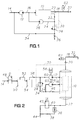
- FIGURE 1 is a simplified block schematic which illustrates a water purifier provided with an inventive valve arrangement
- FIGURE 2 illustrates schematically and in more detail a modified embodiment of a water purifier provided with an inventive valve arrangement
- FIGURES 3 and 4 are respectively cross-sectional views of two pressure-limiting valves, in accordance with the invention.
- water to be purified is passed to a purifying or filtering unit 10 through an inlet pipe 14, a high-pressure pump 12 and a pressure line 16. Extending from the filtering unit 10 is an outlet conduit 18 for purified water and an reject conduit 22 for the rejected or contaminated water which has passed through the filtering unit.
- the high-pressure pump 12 is conveniently a displacement pump, a lamella pump, which is able to handle a water flow that is substantially proportional to the speed of the pump.
- the filter unit 10 is of a known kind and may include either a semi-permeable membrane which functions in accordance with the reverse osmosis principle, or a manofilter or an ultrafilter type, as desired.
- a filter unit 10 will normally include an essentially tubular separator unit (not shown) having a membrane or filter supporting structure. Water to be purified is streamed or flushed past the outer surface of the unit under overpressure, so that some of the water will be pressed through the unit and into its tubular interior and transported therefrom as purified water.
- One such rinsing circuit is included in the FIGURE 1 embodiment and comprises a return line 24 which branches from the reject conduit 22 and which incorporates a centrifugal-type circulation pump 26, for instance a side-channel pump, having a large flow which may be at least five times greater, and preferably more than ten times greater than the flow delivered by the high-pressure pump 12.
- the water circulating in the return line 24 is intended to be held at a high pressure generated by the high-pressure pump 12, this pressure being determined by a pressure-limiting valve 28 incorporated in the return line downstream of the reject conduit 22, in accordance with the invention.
- the pressure-limiting valve 28 is controlled through the agency of a control line 30 in response to the pressure occurrent in the purified water outlet conduit 18. In turn, this pressure is determined by the pressure drop across the purified-water tapping valve, or tap, 32, so that when the tap valve 32 is opened to a small extent, the pressure-limiting valve 28 will allow more reject to pass to the return line 34, so that the high pressure prevailing in the return line 24 will not rise above a predetermined level.
- the pressure-limiting valve 28 is suitably of the kind with which the inlet pressure is limited by a spring force in combination with the pressure in the control conduit 30.
- the pressure-limiting valve 28 is preferably also dimensioned so as to constantly allow a minimum flow to pass through the valve when the water purifier is in operation, i.e. when the high-pressure pump 12 is running. this will completely avoid the occurrence of valve knocks (hammering) and pressure surges when manipulating the tap valve 32.
- FIGURES 3 and 4 illustrate respectively two constructive exemplifying embodiments of the inventive pressure-limiting valve 28, here reference generally 28A and 28B.
- the valve 28A illustrated in FIGURE 3 includes a generally cylindrical valve housing 70 which includes an inlet channel 72 for connection to the conduit 22 of the FIGURE 1 illustration or the conduit 34 of the FIGURE 2 illustration. Extending from the opposite side of the valve housing 70 is a bore 74 which accommodates a valve body 90 which is biassed by a helical spring 110 against a seating 78 in the valve housing 70, said spring being mounted in the valve housing 70 by means of a setting screw 112.
- the seating-side of the valve body 90 is provided with a rubber sealing plate 96 having a circular sealing bead 98 extending around the outer periphery thereof.
- the valve housing 70 also includes a diameter-reducing shoulder 76 which coacts with a corresponding shoulder 94 on the valve body 90.
- valve housing 70 Also provided in the valve housing 70 are two radial bores 80 and 82, of which one bore, 80, forms the valve outlet opening, whereas the other bore, 82, is intended for connection with the water-purifier control conduit 30.
- the bore opening, 82 is intended to introduce the control pressure between the shoulders 76 and 94 so as to exert an opening force on the valve body and therewith amplify the opening force exerted by the pressure in the valve inlet channel 72.
- the bores openings 80 and 82 are intended for connection with associated conduits by means of banjo-couplings, not shown.
- peripheral grooves 86, 86 are provided on the outer surface of the valve housing 70 in the vicinity of respective bore openings 80, 82.
- the valve body is sealed in the housing by means of O-rings 100.
- a drainage channel 84 which communicates with a ring groove in the valve body between two O-ring seals 100 is formed in the valve housing 70 between the bore openings 80 and 82.
- the drainage channel 84 is intended to ensure satisfactory sealing of the O-rings by one-sided pressure application, and to prevent the reject flow passing through the valve from mixing with the purified control-pressure fluid.
- the pressure-limiting valve 28B of FIGURE 4 differs from the valve 28A of FIGURE 3 in that the valve body 90 includes pressure equalizing channels 104, 106 which are active in compensating or hydraulically force-balancing the valve body 90 against the pressure in the outlet opening 80, since this pressure can be delivered to a space 114 within the setting screw 112 and there act on the rear side of the valve body 90 so as to pressure-balance the valve body.
- the control pressure required in the control conduit 30 is therewith independent of the pressure in the outlet bore 80.
- the embodiment illustrated in FIGURE 4 is particularly beneficial when the pressure-limiting valve is coupled in a pressurized return conduit 34, as in the case of the embodiment illustrated in FIGURE 2, which will be described below.
- the purified-water outlet conduit 18 may also include a check valve 20 which, when the tap valve 32 is closed, maintains the control pressure in the conduit leading to the pressure-limiting valve 28 when the high-pressure pump 12 is shut down.
- a second return line 34 branches from the reject conduit 22 at a location downstream of the pressure-limiting valve 28. This second return line returns to the inlet conduit 14 part of the flow that passes through the pressure-limiting valve, i.e. to a point upstream of the high-pressure pump 12. That part of the contaminated water which constantly leaves the system to a waste outlet therewith passes through a constriction or a constant flow valve 36.
- the pressure of the water purifier can be caused to follow the variations in the outtake of purified water in a technically simple controlled fashion.
- a circulation flow of high pressure and of large, essentially constant flow, and a circulation flow of low pressure which can be permitted to vary in response to the purified water outtake.
- This enables not only the circulation pump 26 to be operated at a constant speed but also the high-pressure pump 12, so that the pumps can be driven by inexpensive alternating current motors, for instance induction motors.
- a pressure switch 62 which is intended to start-up the water purifier through the agency of an electronic control circuit (not shown), i.e. to start-up the pump 12 when the conduit pressure in the vicinity of the tap has fallen beneath a predetermined value, e.g. a value of 0.3 MPa, and to shut-down the water purifier when the pressure has reached another, preset value, e.g. a value of 0.7 MPa.
- the pressure-limiting valve 28 maintains the system pressure at a level which is preferably higher than 1 MPa, e.g. 1.5 MPa.
- the pressure-limiting valve 28 is preferably constructed so that the system pressure will be maximum, for instance 1.5 MPa, at maximum flow through the water purifier, i.e. when the pressure in the outlet conduit 18 approaches zero, and so as to lie slightly above the pressure in the outlet conduit 18 when the flow is low, i.e. when the pressure in the outlet conduit 18 is equal to the shut-off pressure, e.g. 0.7 MPa.
- the system pressure is thus caused to follow the variations in the water outtake through the conduit 18.
- the various pressure levels in the pressure-limiting valve can be defused with drainage holes (not shown).
- the inventive valve arrangement is particularly suitable for use in water purifiers which operate in accordance with the reverse osmosis principle.
- a water purifier of this kind can require an overpressure of about 1.5 MPa to overcome the osmotic counterpressure in the semi-permeable membrane.
- the pressure which reaches the water conduit system can be restricted to about 0.7 MPa by the pressure-limiting valve mounted in the reject conduit, so as not to exceed the normal water conduit pressure.
- the exemplifying embodiment illustrated in FIGURE 2 differs from the FIGURE 1 embodiment mainly in that the pressure-limiting valve 28 is placed in the return line 34 for the returned variable rejected flow, instead of in the reject conduit between the two return lines of the FIGURE 1 embodiment.
- the reject conduit for contaminated water is divided within the filter unit 10 into a reject conduit 46 and a reject conduit 22, this division being shown only schematically.
- the reject conduit 22 extends to an outlet 44 through the constriction or constant flow valve 36 and is also provided with a shunt 40 which incorporates a magnetically controlled rinsing valve 42.
- the rinsing valve 42 is normally closed, but can be opened by means of a control unit (not shown) when the filter unit requires additional cleaning.
- the other branch reject conduit 46 which is under high pressure in this case, is branched to the return line 24 with the pump 26 and also to a first high-pressure part of the second return line 34, which is terminated in the pressure-limiting valve 28, downstream of which the pressure-limited return flow is returned to an inlet conduit 56 where it is mixed with newly arriving water and then passed to the high-pressure pump 12.
- the inventive valve arrangement enables the pumps to work at a constant speed and, when suitably dimensioned, also to be driven by a common motor 58 via a common shaft 60, 60, as illustrated in FIGURE 2. This will enable a simple construction to be obtained at low costs.
- the inlet conduit 14 for water to be purified also incorporates an inlet valve 48 and two filter houses 50 and 54 which are mutually connected in series by means of a conduit 52.
- a first filter house, 50 may contain a particle filter, and the other filter house, 54, an active carbon filter for preparatory cleansing of the incoming water.
Landscapes
- Engineering & Computer Science (AREA)
- Water Supply & Treatment (AREA)
- Chemical & Material Sciences (AREA)
- Chemical Kinetics & Catalysis (AREA)
- Nanotechnology (AREA)
- Separation Using Semi-Permeable Membranes (AREA)
- Details Of Valves (AREA)
- Filtration Of Liquid (AREA)
- Water Treatment By Sorption (AREA)
Description
- The present invention relates to a pressurized water purifier of the kind which comprises an inlet conduit, a pressure-elevating pump incorporated in the inlet conduit, a filter or membrane type purifying unit, a purified-water outlet conduit, and a reject conduit for concentrated non-purified or contaminated water.
- A problem with known pressurized water purifiers resides in the difficulty of achieving a uniform or non-pulsating output flow of purified water independently of the size of the flow. This problem is associated with the fact that in order to overcome the filter or membrane counterpressure, it is necessary for water purifiers of this type to operate at an internal pressure greater than 1 MPa, this pressure of 1 MPa being the maximum pressure for which a domestic water system in which the water purifier is installed is normally constructed.
- An object of the present invention is to provide a valve arrangement of the aforesaid kind which will enable, with the aid of simple control/technical means, the water purifier to deliver a purified water flow which even in a part-load region will never exceed 1 MPa, while ensuring, at the same time, that the flow exiting from the water purifier will be as smooth as possible, with minimum pulsation.
- This object is achieved with an inventive valve arrangement that has the characterizing features set forth in the characterizing clause of Claim 1.
- According to one aspect of the invention, there is incorporated in the reject conduit a pressure-limiting valve which is controlled by the pressure occurrent in the outlet conduit. By causing the pressure in the purifying system to vary in this way in accordance with the pressure in the outlet conduit, as the pressure in the outlet conduit is raised when a small quantity of water is taken from the system, the pressure of the water which passes through the purifying unit will decrease. In the opposite case, i.e. when the pressure in the outlet conduit decreases as large quantities of purified water are taken from the system, the system pressure upstream of the pressure-limiting valve is increased so that the pressure drop across the purifying unit and therewith the outflow of the purified water will increase as a result thereof.
- In other words, the system is controlled positively, so that the flow of purified water is able to follow the changes in the extent to which a tap valve in the outlet conduit is opened. Because the pressure of the water purifier is controlled through the agency of the reject flow pressure, it is not necessary to control the flow generated by the high-pressure pump, and this flow can be driven by an inexpensive, constant speed electric motor, such as an induction motor.
- Other features of the invention and advantages afforded thereby will be evident from the remaining Claims and also from the following detailed description of the invention.
- The invention will now be described in more detail with reference to exemplifying embodiments thereof and also with reference to the accompanying drawings, in which FIGURE 1 is a simplified block schematic which illustrates a water purifier provided with an inventive valve arrangement; FIGURE 2 illustrates schematically and in more detail a modified embodiment of a water purifier provided with an inventive valve arrangement; and FIGURES 3 and 4 are respectively cross-sectional views of two pressure-limiting valves, in accordance with the invention.
- In the FIGURE 1 embodiment, water to be purified is passed to a purifying or filtering
unit 10 through aninlet pipe 14, a high-pressure pump 12 and apressure line 16. Extending from thefiltering unit 10 is anoutlet conduit 18 for purified water and an rejectconduit 22 for the rejected or contaminated water which has passed through the filtering unit. The high-pressure pump 12 is conveniently a displacement pump, a lamella pump, which is able to handle a water flow that is substantially proportional to the speed of the pump. - The
filter unit 10 is of a known kind and may include either a semi-permeable membrane which functions in accordance with the reverse osmosis principle, or a manofilter or an ultrafilter type, as desired. Such afilter unit 10 will normally include an essentially tubular separator unit (not shown) having a membrane or filter supporting structure. Water to be purified is streamed or flushed past the outer surface of the unit under overpressure, so that some of the water will be pressed through the unit and into its tubular interior and transported therefrom as purified water. In order to maintain the lowest possible pressure drop across the filter unit, with the intention of reducing the energy cost of the requisite pump work, it is endeavoured to maintain a low concentration of the loose or particulate contaminants on the outer surface of the membrane or the filters, these impurities otherwise tending to collect on said surfaces and therewith increase the pressure drop across the filter, by virtue of increased osmotic counterpressure or clogging of the filters. As previously mentioned, it is known to return a part of the pressurized non-filtered water, or reject, to the filter unit so as to continuously rinse the unit clean of impurities. - One such rinsing circuit is included in the FIGURE 1 embodiment and comprises a
return line 24 which branches from thereject conduit 22 and which incorporates a centrifugal-type circulation pump 26, for instance a side-channel pump, having a large flow which may be at least five times greater, and preferably more than ten times greater than the flow delivered by the high-pressure pump 12. The water circulating in thereturn line 24 is intended to be held at a high pressure generated by the high-pressure pump 12, this pressure being determined by a pressure-limitingvalve 28 incorporated in the return line downstream of the rejectconduit 22, in accordance with the invention. - The pressure-limiting
valve 28 is controlled through the agency of acontrol line 30 in response to the pressure occurrent in the purifiedwater outlet conduit 18. In turn, this pressure is determined by the pressure drop across the purified-water tapping valve, or tap, 32, so that when thetap valve 32 is opened to a small extent, the pressure-limitingvalve 28 will allow more reject to pass to thereturn line 34, so that the high pressure prevailing in thereturn line 24 will not rise above a predetermined level. The pressure-limitingvalve 28 is suitably of the kind with which the inlet pressure is limited by a spring force in combination with the pressure in thecontrol conduit 30. The pressure-limitingvalve 28 is preferably also dimensioned so as to constantly allow a minimum flow to pass through the valve when the water purifier is in operation, i.e. when the high-pressure pump 12 is running. this will completely avoid the occurrence of valve knocks (hammering) and pressure surges when manipulating thetap valve 32. - FIGURES 3 and 4 illustrate respectively two constructive exemplifying embodiments of the inventive pressure-limiting
valve 28, here reference generally 28A and 28B. - The
valve 28A illustrated in FIGURE 3 includes a generallycylindrical valve housing 70 which includes aninlet channel 72 for connection to theconduit 22 of the FIGURE 1 illustration or theconduit 34 of the FIGURE 2 illustration. Extending from the opposite side of thevalve housing 70 is a bore 74 which accommodates avalve body 90 which is biassed by ahelical spring 110 against aseating 78 in thevalve housing 70, said spring being mounted in thevalve housing 70 by means of asetting screw 112. The seating-side of thevalve body 90 is provided with arubber sealing plate 96 having acircular sealing bead 98 extending around the outer periphery thereof. Thevalve housing 70 also includes a diameter-reducing shoulder 76 which coacts with acorresponding shoulder 94 on thevalve body 90. Also provided in thevalve housing 70 are tworadial bores purifier control conduit 30. The bore opening, 82, is intended to introduce the control pressure between theshoulders 76 and 94 so as to exert an opening force on the valve body and therewith amplify the opening force exerted by the pressure in thevalve inlet channel 72. Thebores openings peripheral grooves valve housing 70 in the vicinity ofrespective bore openings drainage channel 84 which communicates with a ring groove in the valve body between two O-ring seals 100 is formed in thevalve housing 70 between thebore openings drainage channel 84 is intended to ensure satisfactory sealing of the O-rings by one-sided pressure application, and to prevent the reject flow passing through the valve from mixing with the purified control-pressure fluid.
The pressure-limitingvalve 28B of FIGURE 4 differs from thevalve 28A of FIGURE 3 in that thevalve body 90 includespressure equalizing channels valve body 90 against the pressure in the outlet opening 80, since this pressure can be delivered to aspace 114 within thesetting screw 112 and there act on the rear side of thevalve body 90 so as to pressure-balance the valve body. The control pressure required in thecontrol conduit 30 is therewith independent of the pressure in theoutlet bore 80. The embodiment illustrated in FIGURE 4 is particularly beneficial when the pressure-limiting valve is coupled in a pressurizedreturn conduit 34, as in the case of the embodiment illustrated in FIGURE 2, which will be described below. - The purified-
water outlet conduit 18 may also include acheck valve 20 which, when thetap valve 32 is closed, maintains the control pressure in the conduit leading to the pressure-limitingvalve 28 when the high-pressure pump 12 is shut down.
In the case of the illustrated embodiment of Figure 1, asecond return line 34 branches from the rejectconduit 22 at a location downstream of the pressure-limitingvalve 28. This second return line returns to the inlet conduit 14 part of the flow that passes through the pressure-limiting valve, i.e. to a point upstream of the high-pressure pump 12. That part of the contaminated water which constantly leaves the system to a waste outlet therewith passes through a constriction or aconstant flow valve 36. However, it lies within the concept of the invention to allow all reject flow to pass to a waste outlet without branching the flow to areturn line 24 and 34 (although not shown). - Thus, by sensing the pressure of the water purifier at the system tapping point and regulating the pressure at the reject flow, the pressure of the water purifier can be caused to follow the variations in the outtake of purified water in a technically simple controlled fashion.
- Furthermore, there is achieved with the aforedescribed arrangement of the
double return lines 24, 34 a circulation flow of high pressure and of large, essentially constant flow, and a circulation flow of low pressure which can be permitted to vary in response to the purified water outtake. This enables not only thecirculation pump 26 to be operated at a constant speed but also the high-pressure pump 12, so that the pumps can be driven by inexpensive alternating current motors, for instance induction motors.
Also arranged in theoutlet conduit 18 is apressure switch 62 which is intended to start-up the water purifier through the agency of an electronic control circuit (not shown), i.e. to start-up thepump 12 when the conduit pressure in the vicinity of the tap has fallen beneath a predetermined value, e.g. a value of 0.3 MPa, and to shut-down the water purifier when the pressure has reached another, preset value, e.g. a value of 0.7 MPa. - The pressure-limiting
valve 28 maintains the system pressure at a level which is preferably higher than 1 MPa, e.g. 1.5 MPa. The pressure-limitingvalve 28 is preferably constructed so that the system pressure will be maximum, for instance 1.5 MPa, at maximum flow through the water purifier, i.e. when the pressure in the outlet conduit 18 approaches zero, and so as to lie slightly above the pressure in the outlet conduit 18 when the flow is low, i.e. when the pressure in theoutlet conduit 18 is equal to the shut-off pressure, e.g. 0.7 MPa. The system pressure is thus caused to follow the variations in the water outtake through theconduit 18. - As an extra safety measure against high pressure, the various pressure levels in the pressure-limiting valve can be defused with drainage holes (not shown).
- The inventive valve arrangement is particularly suitable for use in water purifiers which operate in accordance with the reverse osmosis principle. A water purifier of this kind can require an overpressure of about 1.5 MPa to overcome the osmotic counterpressure in the semi-permeable membrane. However, the pressure which reaches the water conduit system can be restricted to about 0.7 MPa by the pressure-limiting valve mounted in the reject conduit, so as not to exceed the normal water conduit pressure.
- In principle, the exemplifying embodiment illustrated in FIGURE 2 differs from the FIGURE 1 embodiment mainly in that the pressure-limiting
valve 28 is placed in thereturn line 34 for the returned variable rejected flow, instead of in the reject conduit between the two return lines of the FIGURE 1 embodiment. In this case, the reject conduit for contaminated water is divided within thefilter unit 10 into areject conduit 46 and areject conduit 22, this division being shown only schematically. Thereject conduit 22 extends to anoutlet 44 through the constriction orconstant flow valve 36 and is also provided with ashunt 40 which incorporates a magnetically controlledrinsing valve 42. Therinsing valve 42 is normally closed, but can be opened by means of a control unit (not shown) when the filter unit requires additional cleaning. - The other branch reject
conduit 46 which is under high pressure in this case, is branched to thereturn line 24 with thepump 26 and also to a first high-pressure part of thesecond return line 34, which is terminated in the pressure-limitingvalve 28, downstream of which the pressure-limited return flow is returned to aninlet conduit 56 where it is mixed with newly arriving water and then passed to the high-pressure pump 12. - The inventive valve arrangement enables the pumps to work at a constant speed and, when suitably dimensioned, also to be driven by a
common motor 58 via acommon shaft - In the FIGURE 2 embodiment, the
inlet conduit 14 for water to be purified also incorporates aninlet valve 48 and twofilter houses conduit 52. A first filter house, 50, may contain a particle filter, and the other filter house, 54, an active carbon filter for preparatory cleansing of the incoming water.
Claims (8)
- A pressurized water purifier comprising an inlet conduit (14, 16) which includes a pressure-elevating pump (12), a filter or membrane type purifying unit (10), a purified water outlet conduit (18) and at least a reject conduit (22, 46) for concentrated contaminated water, characterized in that the reject conduit (22; 46) includes a pressure-limiting valve (28) which is controlled by the pressure in the outlet conduit (18).
- A water purifier according to Claim 1, characterized in that the pressure-limiting valve (28A; 28B) comprises a valve housing (70) which includes a valve body (90) which can be moved in a valve opening direction by the pressures that prevails in the reject conduit (22; 46) and the outlet conduit (18), against the action of a spring (110).
- A water purifier according to Claim 2, characterized in that the valve body (90) is constructed so as to be hydraulically force-balanced against its displacement in response to pressure acting on the outlet of the valve (28B).
- A water purifier according to any one of the preceding Claims, characterized by a check valve (20) which functions to maintain the pressure in the outlet conduit (18) when a motor (58) which drives the pressure-elevating pump (12) is shut-down.
- A water purifier according to any one of the preceding Claims, characterized by a pressure switch (62) in the outlet conduit (18), said switch functioning to control the starting and stopping of a motor (58) which drives the pressure-elevating pump (12).
- A water purifier according to any one of the preceeding claims, characterized in that the reject conduit (22, 46) branches to two return lines (24, 34) leading to the inlet part of the membrane type purifying unit (10).
- A water purifier according to claim 6 characterized in that the pressure-limiting valve (28) is coupled in the reject conduit (22) between the two return lines (24, 34).
- A water purifier according to claim 6 characterized in that the pressure-limiting valve (28) is coupled in the return line (34) common to the reject conduit (46) downstream of the other return line (24).
Applications Claiming Priority (2)
| Application Number | Priority Date | Filing Date | Title |
|---|---|---|---|
| SE9201513A SE509755C2 (en) | 1992-05-13 | 1992-05-13 | Valve arrangement for a pressurized water purifier |
| SE9201513 | 1992-05-13 |
Publications (2)
| Publication Number | Publication Date |
|---|---|
| EP0570350A1 EP0570350A1 (en) | 1993-11-18 |
| EP0570350B1 true EP0570350B1 (en) | 1996-11-06 |
Family
ID=20386239
Family Applications (1)
| Application Number | Title | Priority Date | Filing Date |
|---|---|---|---|
| EP93850100A Expired - Lifetime EP0570350B1 (en) | 1992-05-13 | 1993-05-05 | A valve arrangement for a pressurized water purifier |
Country Status (7)
| Country | Link |
|---|---|
| US (1) | US5401395A (en) |
| EP (1) | EP0570350B1 (en) |
| JP (1) | JP3274738B2 (en) |
| DE (1) | DE69305786T2 (en) |
| DK (1) | DK0570350T3 (en) |
| ES (1) | ES2095031T3 (en) |
| SE (1) | SE509755C2 (en) |
Families Citing this family (16)
| Publication number | Priority date | Publication date | Assignee | Title |
|---|---|---|---|---|
| ZA9711050B (en) * | 1996-09-09 | 1999-05-07 | Quentin John Seaton Hartley | Management of a body of water |
| SE510360C2 (en) * | 1996-10-01 | 1999-05-17 | Electrolux Ab | Water purifier and pressure equalizer |
| US6074551A (en) * | 1998-04-30 | 2000-06-13 | Culligan Water Conditioning Of Fairfield County | Automatic cleaning system for a reverse osmosis unit in a high purity water treatment system |
| KR100397874B1 (en) * | 2001-01-03 | 2003-09-13 | 김명철 | a device of intake valve for clean water |
| DE10327401A1 (en) * | 2003-06-18 | 2005-01-05 | Ksb Aktiengesellschaft | Pump with additional fluid supply |
| US8128821B2 (en) * | 2006-06-14 | 2012-03-06 | Fluid Equipment Development Company, Llc | Reverse osmosis system with control based on flow rates in the permeate and brine streams |
| US20080105617A1 (en) * | 2006-06-14 | 2008-05-08 | Eli Oklejas | Two pass reverse osmosis system |
| DE102006044497B4 (en) * | 2006-09-21 | 2014-03-27 | Manfred Völker | Apparatus for water treatment according to the principle of reverse osmosis |
| US8529761B2 (en) | 2007-02-13 | 2013-09-10 | Fluid Equipment Development Company, Llc | Central pumping and energy recovery in a reverse osmosis system |
| US8147692B2 (en) * | 2008-01-04 | 2012-04-03 | Fluid Equipment Development Company, Llc | Batch-operated reverse osmosis system with multiple membranes in a pressure vessel |
| US7892429B2 (en) | 2008-01-28 | 2011-02-22 | Fluid Equipment Development Company, Llc | Batch-operated reverse osmosis system with manual energization |
| US8710406B2 (en) * | 2008-09-19 | 2014-04-29 | Conair Corporation | Safety device and method for electric heating appliances |
| EP2799127A4 (en) * | 2011-12-26 | 2015-10-07 | Hbio Reto Xxi S L | System for flow control in filters |
| KR101853281B1 (en) | 2012-04-20 | 2018-04-30 | 플루이드 이큅먼트 디벨롭먼트 컴패니, 엘엘씨 | Reverse osmosis system with energy recovery devices |
| BE1021456B1 (en) * | 2012-09-11 | 2015-11-26 | Ar Services Bvba | DEVICE FOR TREATING LIQUIDS USING A CONTROLLED PISTON BULK WITH FLOW |
| US9975089B2 (en) | 2016-10-17 | 2018-05-22 | Fluid Equipment Development Company, Llc | Method and system for performing a batch reverse osmosis process using a tank with a movable partition |
Family Cites Families (10)
| Publication number | Priority date | Publication date | Assignee | Title |
|---|---|---|---|---|
| GB757721A (en) * | 1953-07-29 | 1956-09-26 | Havilland Engine Co Ltd | Fuel supply systems for liquid fuel engines |
| US3389796A (en) * | 1966-01-13 | 1968-06-25 | Int Harvester Co | Balanced pressure relief valve |
| BE758365A (en) * | 1969-11-03 | 1971-04-16 | Pressed Steel Fisher Ltd | METHOD AND APPARATUS FOR TREATMENT OF AQUEOUS EFFLUENTS CONTAINING COATING COMPOSITIONS |
| US4026800A (en) * | 1974-04-19 | 1977-05-31 | National Medical Care, Inc. | Dialysis apparatus |
| DK434974A (en) * | 1974-08-14 | 1976-02-15 | Danske Mejeriers Maskinfabrik | MEMBRANE FILTERING SYSTEMS |
| JPS5626503A (en) * | 1979-08-10 | 1981-03-14 | Hitachi Ltd | Removing solid material from liquid |
| US4773991A (en) * | 1987-03-13 | 1988-09-27 | Baxter Travenol Laboratories, Inc. | Water purification system fluid path |
| US4971689A (en) * | 1988-09-26 | 1990-11-20 | Burrows Bruce D | Reverse osmosis water purification system with improved pressure relief value |
| US4963253A (en) * | 1989-01-03 | 1990-10-16 | Yen Richard C K | Anti-clogging and dialysis device for filtration systems |
| DE3913920A1 (en) * | 1989-04-27 | 1990-10-31 | Kaercher Gmbh & Co Alfred | WASHING MACHINE FOR MOTOR VEHICLES |
-
1992
- 1992-05-13 SE SE9201513A patent/SE509755C2/en unknown
-
1993
- 1993-05-05 DE DE69305786T patent/DE69305786T2/en not_active Expired - Fee Related
- 1993-05-05 EP EP93850100A patent/EP0570350B1/en not_active Expired - Lifetime
- 1993-05-05 ES ES93850100T patent/ES2095031T3/en not_active Expired - Lifetime
- 1993-05-05 DK DK93850100.4T patent/DK0570350T3/en active
- 1993-05-11 US US08/059,933 patent/US5401395A/en not_active Expired - Lifetime
- 1993-05-12 JP JP11069693A patent/JP3274738B2/en not_active Expired - Fee Related
Also Published As
| Publication number | Publication date |
|---|---|
| JP3274738B2 (en) | 2002-04-15 |
| EP0570350A1 (en) | 1993-11-18 |
| JPH0639246A (en) | 1994-02-15 |
| DE69305786T2 (en) | 1997-05-15 |
| US5401395A (en) | 1995-03-28 |
| DK0570350T3 (en) | 1997-04-14 |
| SE9201513D0 (en) | 1992-05-13 |
| SE9201513L (en) | 1993-11-14 |
| DE69305786D1 (en) | 1996-12-12 |
| ES2095031T3 (en) | 1997-02-01 |
| SE509755C2 (en) | 1999-03-01 |
Similar Documents
| Publication | Publication Date | Title |
|---|---|---|
| EP0570349B1 (en) | A method and apparatus for purifying water | |
| US5401395A (en) | Valve arrangement for a pressurized water purifier | |
| US5879558A (en) | Water conserving reverse osmosis unit and method of operating it | |
| WO2018036753A1 (en) | Reverse osmosis water purifier | |
| KR20180125023A (en) | Household water purification system | |
| EP1289632B1 (en) | Method and device for purifying water | |
| CN112759097A (en) | Reverse osmosis filtration system | |
| CN219782281U (en) | Table type water purifying and drinking machine without pure water tank control waterway | |
| RU2641923C1 (en) | Water purification plant | |
| RU2058272C1 (en) | Water cleaning-up station | |
| CN213112890U (en) | Ultrapure water system | |
| EP0938361B1 (en) | Water purifier | |
| CN212315751U (en) | RO water purification system and RO water purifier | |
| TWM642281U (en) | DC motor pressure stabilization system for reverse osmosis water purifier | |
| JPS61132791A (en) | Pump | |
| AU2021389057A1 (en) | A desalination plant | |
| CN221565870U (en) | Water purification system | |
| RU2216392C2 (en) | Membrane plant | |
| CN222809282U (en) | A zero-stale water barrel-type reverse osmosis water purification pipeline system and water purifier | |
| CN211734016U (en) | Waterway system and water purifier comprising same | |
| CN221235320U (en) | Water purification system | |
| RU2094657C1 (en) | Adjustable hydroelectric power plant | |
| KR102576364B1 (en) | Apparatus for water purification with easy water filter replacement | |
| CN222922954U (en) | Water purifier with single reverse osmosis unit | |
| CN221854318U (en) | Water purification equipment |
Legal Events
| Date | Code | Title | Description |
|---|---|---|---|
| PUAI | Public reference made under article 153(3) epc to a published international application that has entered the european phase |
Free format text: ORIGINAL CODE: 0009012 |
|
| AK | Designated contracting states |
Kind code of ref document: A1 Designated state(s): BE DE DK ES FR GB IT NL |
|
| 17P | Request for examination filed |
Effective date: 19931213 |
|
| 17Q | First examination report despatched |
Effective date: 19950307 |
|
| GRAG | Despatch of communication of intention to grant |
Free format text: ORIGINAL CODE: EPIDOS AGRA |
|
| GRAH | Despatch of communication of intention to grant a patent |
Free format text: ORIGINAL CODE: EPIDOS IGRA |
|
| GRAH | Despatch of communication of intention to grant a patent |
Free format text: ORIGINAL CODE: EPIDOS IGRA |
|
| GRAA | (expected) grant |
Free format text: ORIGINAL CODE: 0009210 |
|
| AK | Designated contracting states |
Kind code of ref document: B1 Designated state(s): BE DE DK ES FR GB IT NL |
|
| REF | Corresponds to: |
Ref document number: 69305786 Country of ref document: DE Date of ref document: 19961212 |
|
| ITF | It: translation for a ep patent filed | ||
| REG | Reference to a national code |
Ref country code: ES Ref legal event code: FG2A Ref document number: 2095031 Country of ref document: ES Kind code of ref document: T3 |
|
| ET | Fr: translation filed | ||
| REG | Reference to a national code |
Ref country code: DK Ref legal event code: T3 |
|
| PLBE | No opposition filed within time limit |
Free format text: ORIGINAL CODE: 0009261 |
|
| STAA | Information on the status of an ep patent application or granted ep patent |
Free format text: STATUS: NO OPPOSITION FILED WITHIN TIME LIMIT |
|
| 26N | No opposition filed | ||
| PGFP | Annual fee paid to national office [announced via postgrant information from national office to epo] |
Ref country code: NL Payment date: 19980531 Year of fee payment: 6 |
|
| PG25 | Lapsed in a contracting state [announced via postgrant information from national office to epo] |
Ref country code: NL Free format text: LAPSE BECAUSE OF NON-PAYMENT OF DUE FEES Effective date: 19991201 |
|
| NLV4 | Nl: lapsed or anulled due to non-payment of the annual fee |
Effective date: 19991201 |
|
| PGFP | Annual fee paid to national office [announced via postgrant information from national office to epo] |
Ref country code: DK Payment date: 20000511 Year of fee payment: 8 |
|
| PGFP | Annual fee paid to national office [announced via postgrant information from national office to epo] |
Ref country code: GB Payment date: 20010502 Year of fee payment: 9 |
|
| PG25 | Lapsed in a contracting state [announced via postgrant information from national office to epo] |
Ref country code: DK Free format text: LAPSE BECAUSE OF NON-PAYMENT OF DUE FEES Effective date: 20010505 |
|
| PGFP | Annual fee paid to national office [announced via postgrant information from national office to epo] |
Ref country code: BE Payment date: 20010625 Year of fee payment: 9 |
|
| REG | Reference to a national code |
Ref country code: GB Ref legal event code: IF02 |
|
| REG | Reference to a national code |
Ref country code: DK Ref legal event code: EBP |
|
| PG25 | Lapsed in a contracting state [announced via postgrant information from national office to epo] |
Ref country code: GB Free format text: LAPSE BECAUSE OF NON-PAYMENT OF DUE FEES Effective date: 20020505 |
|
| PG25 | Lapsed in a contracting state [announced via postgrant information from national office to epo] |
Ref country code: BE Free format text: LAPSE BECAUSE OF NON-PAYMENT OF DUE FEES Effective date: 20020531 |
|
| GBPC | Gb: european patent ceased through non-payment of renewal fee |
Effective date: 20020505 |
|
| REG | Reference to a national code |
Ref country code: FR Ref legal event code: TP |
|
| REG | Reference to a national code |
Ref country code: ES Ref legal event code: PC2A |
|
| PGFP | Annual fee paid to national office [announced via postgrant information from national office to epo] |
Ref country code: FR Payment date: 20070518 Year of fee payment: 15 |
|
| REG | Reference to a national code |
Ref country code: FR Ref legal event code: ST Effective date: 20090119 |
|
| PG25 | Lapsed in a contracting state [announced via postgrant information from national office to epo] |
Ref country code: FR Free format text: LAPSE BECAUSE OF NON-PAYMENT OF DUE FEES Effective date: 20080602 |
|
| PGFP | Annual fee paid to national office [announced via postgrant information from national office to epo] |
Ref country code: ES Payment date: 20090629 Year of fee payment: 17 |
|
| PGFP | Annual fee paid to national office [announced via postgrant information from national office to epo] |
Ref country code: DE Payment date: 20090605 Year of fee payment: 17 |
|
| PGFP | Annual fee paid to national office [announced via postgrant information from national office to epo] |
Ref country code: IT Payment date: 20090626 Year of fee payment: 17 |
|
| PG25 | Lapsed in a contracting state [announced via postgrant information from national office to epo] |
Ref country code: IT Free format text: LAPSE BECAUSE OF NON-PAYMENT OF DUE FEES Effective date: 20100505 |
|
| PG25 | Lapsed in a contracting state [announced via postgrant information from national office to epo] |
Ref country code: DE Free format text: LAPSE BECAUSE OF NON-PAYMENT OF DUE FEES Effective date: 20101201 |
|
| REG | Reference to a national code |
Ref country code: ES Ref legal event code: FD2A Effective date: 20110715 |
|
| PG25 | Lapsed in a contracting state [announced via postgrant information from national office to epo] |
Ref country code: ES Free format text: LAPSE BECAUSE OF NON-PAYMENT OF DUE FEES Effective date: 20110705 |
|
| PG25 | Lapsed in a contracting state [announced via postgrant information from national office to epo] |
Ref country code: ES Free format text: LAPSE BECAUSE OF NON-PAYMENT OF DUE FEES Effective date: 20100506 |