EP0570319A2 - Asynchronous full-duplex communication using two half-duplex channels with software handshaking - Google Patents
Asynchronous full-duplex communication using two half-duplex channels with software handshaking Download PDFInfo
- Publication number
- EP0570319A2 EP0570319A2 EP93480028A EP93480028A EP0570319A2 EP 0570319 A2 EP0570319 A2 EP 0570319A2 EP 93480028 A EP93480028 A EP 93480028A EP 93480028 A EP93480028 A EP 93480028A EP 0570319 A2 EP0570319 A2 EP 0570319A2
- Authority
- EP
- European Patent Office
- Prior art keywords
- computer
- computers
- acknowledgement
- communication
- micro
- Prior art date
- Legal status (The legal status is an assumption and is not a legal conclusion. Google has not performed a legal analysis and makes no representation as to the accuracy of the status listed.)
- Withdrawn
Links
Images





Classifications
-
- G—PHYSICS
- G06—COMPUTING OR CALCULATING; COUNTING
- G06F—ELECTRIC DIGITAL DATA PROCESSING
- G06F15/00—Digital computers in general; Data processing equipment in general
- G06F15/16—Combinations of two or more digital computers each having at least an arithmetic unit, a program unit and a register, e.g. for a simultaneous processing of several programs
- G06F15/163—Interprocessor communication
- G06F15/17—Interprocessor communication using an input/output type connection, e.g. channel, I/O port
-
- H—ELECTRICITY
- H04—ELECTRIC COMMUNICATION TECHNIQUE
- H04L—TRANSMISSION OF DIGITAL INFORMATION, e.g. TELEGRAPHIC COMMUNICATION
- H04L12/00—Data switching networks
- H04L12/28—Data switching networks characterised by path configuration, e.g. LAN [Local Area Networks] or WAN [Wide Area Networks]
- H04L12/40—Bus networks
- H04L12/40143—Bus networks involving priority mechanisms
-
- H—ELECTRICITY
- H04—ELECTRIC COMMUNICATION TECHNIQUE
- H04L—TRANSMISSION OF DIGITAL INFORMATION, e.g. TELEGRAPHIC COMMUNICATION
- H04L69/00—Network arrangements, protocols or services independent of the application payload and not provided for in the other groups of this subclass
- H04L69/14—Multichannel or multilink protocols
-
- H—ELECTRICITY
- H04—ELECTRIC COMMUNICATION TECHNIQUE
- H04L—TRANSMISSION OF DIGITAL INFORMATION, e.g. TELEGRAPHIC COMMUNICATION
- H04L69/00—Network arrangements, protocols or services independent of the application payload and not provided for in the other groups of this subclass
- H04L69/26—Special purpose or proprietary protocols or architectures
-
- H—ELECTRICITY
- H04—ELECTRIC COMMUNICATION TECHNIQUE
- H04L—TRANSMISSION OF DIGITAL INFORMATION, e.g. TELEGRAPHIC COMMUNICATION
- H04L9/00—Cryptographic mechanisms or cryptographic arrangements for secret or secure communications; Network security protocols
- H04L9/40—Network security protocols
-
- H—ELECTRICITY
- H04—ELECTRIC COMMUNICATION TECHNIQUE
- H04L—TRANSMISSION OF DIGITAL INFORMATION, e.g. TELEGRAPHIC COMMUNICATION
- H04L67/00—Network arrangements or protocols for supporting network services or applications
- H04L67/01—Protocols
- H04L67/12—Protocols specially adapted for proprietary or special-purpose networking environments, e.g. medical networks, sensor networks, networks in vehicles or remote metering networks
Definitions
- the present invention generally relates to digital communications and, more particularly, to asynchronous communications between two or more computers wherein the computers are continuously connected by a physical link but operate autonomously between communications.
- the invention has particular application to computer controlled manufacturing processes and tools.
- a main computer coordinates a series of tasks by interfacing with various types of peripheral equipment.
- peripherals can be inputs (e.g., pressure or proximity sensors) or outputs (e.g., actuators or motors) controlled directly by the main computer or indirectly by a slave computer.
- peripherals e.g., pressure or proximity sensors
- outputs e.g., actuators or motors
- the most common interface is the RS-232-C serial input/output (I/O) standard.
- EIA Electronics Industries Association
- ISO International Standards Organization
- RS-232-C standards such as RS-232-C that govern the electrical characteristics of connections between computers and various peripherals.
- the RS-232 connection is a standard serial input/output (I/O) connection, and the connector normally used for this connection is the DB-25 connector, the design of which is controlled by ISO document 2113.
- half-duplex blocks of data can be transmitted in both directions, but in only one direction at a time.
- Traditional hardware handshaking for half-duplex communication between a DTE (data terminal equipment) and a DCE (data communications equipment) is as follows:
- RS-232 handshaking protocol which is an industry standard, works well for most computer communications
- a problem has been encountered in applying this protocol to a computer controlled manufacturing environment. More specifically, a manufacturing tool which performs a complex series of operations can be effectively controlled by a plurality of micro computers, thereby dividing the tool into a plurality of less complex "subtools" each controlled by one of the micro computers.
- the micro computers typically do not have sufficient capacity to perform more than a limited number of tasks and, in any case, must be coordinated so that the sequence of operations is performed as designed.
- the task of coordinating the several micro computers is usually assigned to a main computer.
- the main computer thus controls the tool sequencing, while the micro computers are responsible for specific tasks, such as motion control.
- the main computer communicates a task or command to a micro computer in order to begin a tool operation
- the main computer is considered the master and the micro computer is the slave.
- the micro computer has finished the task or command, it initiates communication with the main computer to update its progress.
- the micro computer is considered the master and the main computer is the slave.
- the main computer and the micro computers operate autonomously, even though they remain physically connected via a cable link. From this example, it can be seen that an individual computer will alternate from a master to a slave. This state change of each computer precludes the use of the EIA industry standard hardware RS-232 handshaking protocol.
- a software asynchronous communication protocol which allows the roles of master and slave to be switched between the computers, depending on the nature and direction of the communication.
- the software incorporates a dwell to accommodate the slowest computer in the system.
- the invention is described in terms of a specific implementation in the field of process control where a main computer communicates with a plurality of micro computers.
- the main computer transmits one or more commands to each of the micro computers, and the micro computers operate autonomously, transmitting status upon completion of each command. It will, however, be understood by those skilled in the digital communication art that the invention is not limited to a process control environment and may be applied to other areas of computer communications where a main computer communicates with a plurality of other computers.
- a main computer 11 controls the tool sequencing, while a plurality of micro computers 121 to 12 n are responsible for specific tool tasks.
- the computer 11 may be an IBM Series/1 computer, and the micro computers may be based on industry standard microprocessors, such as the Motorola 68000 series or the Intel ix86 series of microprocessors.
- industry standard microprocessors such as the Motorola 68000 series or the Intel ix86 series of microprocessors.
- different computers could be used and, depending on the application and resources available, it is not necessary that all the micro computers 121 to 12 n be of the same type.
- the micro computers are typically mounted in a rack (not shown) and, for the sake simplifying the illustration, are represented by four functions, a screener function 121, a mask cleaner function 122, a magazine loader function 123 and a robot function 124, as might be used in an integrated circuit (IC) processing facility.
- IC integrated circuit
- Each of these micro computers 121 to 124 are connected to the main computer 11 via respective standard RS-232 connections 131, 132, 133, and 134.
- the Series/1 computer 11 delegates tasks to a plurality of less complex subtools, each controlled by a micro computer 121 to 124.
- the main computer 11 thus controls the tool sequencing, while the micro computers 121 to 124 are responsible for specific tasks such as motion control.
- the main computer 11 would communicate one or more tasks or commands to a micro computer 12 i in order to begin a tool function.
- the micro computer 12 i would start the task, monitor progress and report back upon completion.
- the main computer 11 would thereby be updated and then send the next group of tasks or commands to the micro computer 12 i .
- data exchange can occur in both directions simultaneously allowing a single channel to be used efficiently.
- the Series/1 computer cannot communicate in full-duplex mode.
- the present invention was developed as a non-standard approach by using two half-duplex channels to simulate a full-duplex channel. This is illustrated in Figure 2, to which reference is now made.
- the tool control software running on the main computer 11 and the micro computers 121 to 12 n uses a string of characters to initiate the data transfer from the master to the slave.
- a command string down to a micro computer 12 i over its command channel.
- a typical command string is shown in Figure 3 and uses framing characters, character count, checksum, data and terminating characters.
- An acknowledgement response is returned back to the Series/1 on the same channel.
- the micro computer 12 i now acts autonomously to compete its task. Upon completion, it sends a status string, as shown in Figure 4, on the status channel to update the Series/1 computer 11.
- An acknowledgement response, again as shown in Figure 5 is returned back to the micro computer 12 i by the main computer 11 on the same channel.
- RTS, CTS, DSR and DTR lines are all tied to an active state, and software is used to simulate the hardware handshaking.
- This software solution consists of a bi-directional control of data and timing dwells. On a half-duplex channel, the bi-directional control of data is necessary to prevent interference. Although this control is usually performed by handshake lines, a less cumbersome method is implemented according to the teaching of this invention:
- a sensitive issue with this configuration is the timing between the computers; that is, the internal WRITE/READ cycle time within each computer. Following the transmission of a command string (WRITE), the main computer 11 must be ready to accept the acknowledgement (READ). If the acknowledgement from the micro computer 12 i arrives sooner than the WRITE/READ cycle time capability of the main computer 11, the acknowledgement will be truncated. This possibility is illustrated in Figure 8 where the acknowledgement at B arrives in very much less than 30 msec. which, for the IBM Series/1 computer, is less than the READ/WRITE cycle time for that computer. Acknowledgements arriving near the WRITE/READ cycle time capability will be truncated intermittently. A similar situation can take place during the transmission of a status string, as illustrated in Figure 9. In this example, the micro computer 12 i transmits a status string for the second move at C to the main computer 11 immediately after receiving the acknowledgement from the main computer at B. Again, the status transmission comes in less than the READ/WRITE cycle time for the main computer 11.
- the main computer 11 is an IBM System/1 computer and there are four micro computers 121 to 124.
- the main computer is the older technology and has a longer WRITE/READ cycle although it has greater storage and processing capacity than the micro computers.
- the inherent modularity of the system shown in Figure 1, however, allows for either the main computer 11 or the micro computers 121 to 12 n to be upgraded.
- the WRITE/READ cycles of the computers used will be different depending on the specific configuration of computers. In other words, it may be that in some installations that the WRITE/READ cycles of the micro computers, or at least some of them, will be longer than that of the main computer.
- FIG. 10 is a flowchart showing the procedure to determine the required dwell time.
- First install an oscilloscope channel on the transmit data line (RS-232, pin 2) and another channel on the receive data line (RS-232, pin 3) at step 21.
- step 22 begin by transmitting a command string from the main computer to the micro computer.
- the oscilloscope determine the time difference between the two at step 23. If the main computer received the full acknowledgement as sent, no dwell time is needed on the micro computer side, and the procedure ends at step 24. However, if the main computer received a truncated acknowledgement, a dwell is necessary on the micro computer side. This dwell time essentially slows the response time of the micro computer so that the main computer will be ready to accept the acknowledgement.
- the duration of the dwell is the time difference determined by the oscilloscope. This value plus some small buffer value is added in step 25, and the procedure is repeated until the timing relationship has been determined to be all right. This same dwell will be incorporated into the software of all the micro computers, if they are of the same type. If the micro computers differ, the same procedure must be performed for each of them.
- micro computers 121 to 12 n need not be identical with the same WRITE/READ cycles, so it is possible that while the WRITE/READ cycle of, say, micro computer 121 may be faster than that of the main computer 11, the WRITE/READ cycle of the main computer 11 could be faster than that of, say, micro computer 122.
- the main computer 11 polls each of the micro computers 121 to 12 n and waits for an acknowledgement from each in turn. The time for the acknowledgement is timed by the main computer. If an acknowledgement is not registered for a micro computer, it is polled again but this time a predetermined guard time is added by the micro computer before sending the acknowledgement. The process is repeated with the guard times being accumulated and stored by each micro computer until it is no longer polled by the main computer. The accumulated guard times constitute the software dwell for that micro computer.
- each micro computer sends a test message to the main computer 11 and waits for an acknowledgement, and the same procedure is followed by the main computer 11 to determine the software dwells that must be incorporated within its communication protocol for each of the micro computers.
- the software sequence according to the invention is shown in Figure 11, to which reference is now made.
- the main computer 11 acting as a master, transmits a command to a micro computer 12 i , acting as a slave.
- the micro computer 12 i performs a software dwell, as indicated by decision block 22, and then returns a command acknowledgement in function block 23.
- the micro computer 12 i acting as a master, transmits a status to the main computer 11, acting as a slave, in order to update tool progress, as indicated in function block 24.
- the main computer 11 performs a software dwell, as indicated by decision block 25, and then returns a status acknowledgement in function block 26.
- a software dwell prior to both the command acknowledgement or status acknowledgement is not always necessary. Often, a dwell must be incorporated only within the faster of the two computers. This dwell essentially slows the faster computer by enough so that the slower computer will be ready to accept the acknowledgement.
- the invention is applicable to any node to node computer communication involving standard RS-232 configuration. It provides both a flexible communication architecture and a less complicated wiring scheme.
Landscapes
- Engineering & Computer Science (AREA)
- Theoretical Computer Science (AREA)
- Computer Networks & Wireless Communication (AREA)
- Signal Processing (AREA)
- Computer Hardware Design (AREA)
- Computer Security & Cryptography (AREA)
- Software Systems (AREA)
- Physics & Mathematics (AREA)
- General Engineering & Computer Science (AREA)
- General Physics & Mathematics (AREA)
- Computing Systems (AREA)
- Computer And Data Communications (AREA)
- Communication Control (AREA)
Abstract
An asynchronous communication protocol between two or more computers allows two half-duplex channels to operate in full-duplex mode using software. The design, consisting of bi-directional control and dwells, emulates the function of hardware handshaking. A more reliable communication interface thus results which is easier to design and use within sets of dissimilar computer systems.
Description
- The present invention generally relates to digital communications and, more particularly, to asynchronous communications between two or more computers wherein the computers are continuously connected by a physical link but operate autonomously between communications. The invention has particular application to computer controlled manufacturing processes and tools. In a process control environment, a main computer coordinates a series of tasks by interfacing with various types of peripheral equipment. These peripherals can be inputs (e.g., pressure or proximity sensors) or outputs (e.g., actuators or motors) controlled directly by the main computer or indirectly by a slave computer. In the case of a distributed system where a main computer communicates asynchronously with one or more slave computers, the most common interface is the RS-232-C serial input/output (I/O) standard.
- There are a number of standards organizations which are important to the establishment of industry standards for digital communications. Among these are the Electronics Industries Association (EIA) and the International Standards Organization (ISO). The EIA publishes standards such as RS-232-C that govern the electrical characteristics of connections between computers and various peripherals. The RS-232 connection is a standard serial input/output (I/O) connection, and the connector normally used for this connection is the DB-25 connector, the design of which is controlled by ISO document 2113.
- Within the RS-232 standard, there exist two types of communication; half-duplex and full-duplex. In half-duplex communication, blocks of data can be transmitted in both directions, but in only one direction at a time. Traditional hardware handshaking for half-duplex communication between a DTE (data terminal equipment) and a DCE (data communications equipment) is as follows:
- 1. The DTE processor initiates contact by raising the data terminal ready (DTR) line.
- 2. The DCE processor responds by raising the data set ready (DSR) line.
- 3. The DTE processor continues by raising the request to send (RTS) line.
- 4. The DCE processor responds by raising the clear to send (CTS) line.
- 5. Data transmission from the DTE to DCE begins. The foregoing protocol is an example of hardware "hand-shaking". In addition to the hardware handshaking, various protocols can be incorporated in the data string to provide data integrity. Examples are parity, check sum, byte count and framing characters.
In full-duplex communication, blocks of data can be transmitted in both directions at the same time. These two-way channels do not require RTS/CTS handshaking leading to a more efficient interface. The disadvantage is the complexity of frequency division multiplexing (FDM) required to prevent interference. - While the RS-232 handshaking protocol, which is an industry standard, works well for most computer communications, a problem has been encountered in applying this protocol to a computer controlled manufacturing environment. More specifically, a manufacturing tool which performs a complex series of operations can be effectively controlled by a plurality of micro computers, thereby dividing the tool into a plurality of less complex "subtools" each controlled by one of the micro computers. The micro computers, however, typically do not have sufficient capacity to perform more than a limited number of tasks and, in any case, must be coordinated so that the sequence of operations is performed as designed. The task of coordinating the several micro computers is usually assigned to a main computer.
- The main computer thus controls the tool sequencing, while the micro computers are responsible for specific tasks, such as motion control. In this configuration, there are two types of communication; command communication and status communication. When the main computer communicates a task or command to a micro computer in order to begin a tool operation, the main computer is considered the master and the micro computer is the slave. On the other hand, when the micro computer has finished the task or command, it initiates communication with the main computer to update its progress. In this case, the micro computer is considered the master and the main computer is the slave.
- Between communications, the main computer and the micro computers operate autonomously, even though they remain physically connected via a cable link. From this example, it can be seen that an individual computer will alternate from a master to a slave. This state change of each computer precludes the use of the EIA industry standard hardware RS-232 handshaking protocol.
- It is therefore an object of the present invention to provide a serial communications link between computers which allows the computers to operate autonomously except when an asynchronous communication is initiated by any one of the computers under a protocol that allows the computers assume the roles of master or slave, depending on the nature and direction of the communication.
- According to the invention, a software asynchronous communication protocol is provided which allows the roles of master and slave to be switched between the computers, depending on the nature and direction of the communication. In order to avoid truncating bit strings transmitted between the computers due to a difference in the WRITE/READ cycles of the computers, the software incorporates a dwell to accommodate the slowest computer in the system.
- The foregoing and other objects, aspects and advantages will be better understood from the following detailed description of a preferred embodiment of the invention with reference to the drawings, in which:
- Figure 1 is a block diagram showing an example of a computer control system for a manufacturing tool on which the invention may be implemented;
- Figure 2 is a high level block diagram showing the basic operation of the invention;
- Figure 3 is a diagram illustrating a typical command string using framing characters;
- Figure 4 is a diagram illustrating a typical status string using framing characters;
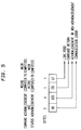
- Figure 5 is a diagram illustrating a typical command and status acknowledgement string;
- Figure 6 is a timing diagram showing the transmission of command strings from a main computer to a micro computer and the acknowledgement responses by the micro computer over the same channel;
- Figure 7 is a timing diagram showing the transmission of status strings from a micro computer to a main computer and acknowledgement responses by the main computer over the same channel;
- Figure 8 is a timing diagram, like Figure 6, showing a command communication timing problem due to the READ/WRITE cycle of the main computer;
- Figure 9 is a timing diagram, like Figure 7, showing a status communication timing problem due to the READ/WRITE cycle of the main computer;
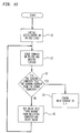
- Figure 10 is a flowchart showing the procedure for determining dwell times to be added to the communications software; and
- Figure 11 is a flowchart illustrating the logic of the software protocol according to the invention.
- The invention is described in terms of a specific implementation in the field of process control where a main computer communicates with a plurality of micro computers. The main computer transmits one or more commands to each of the micro computers, and the micro computers operate autonomously, transmitting status upon completion of each command. It will, however, be understood by those skilled in the digital communication art that the invention is not limited to a process control environment and may be applied to other areas of computer communications where a main computer communicates with a plurality of other computers.
- Referring now to the drawings, and more particularly to Figure 1, there is shown an example of a
tool control application 10 employing multiple computers used in the operation of a tool (not shown). Amain computer 11 controls the tool sequencing, while a plurality ofmicro computers 121 to 12n are responsible for specific tool tasks. In a specific embodiment, thecomputer 11 may be an IBM Series/1 computer, and the micro computers may be based on industry standard microprocessors, such as the Motorola 68000 series or the Intel ix86 series of microprocessors. Of course, different computers could be used and, depending on the application and resources available, it is not necessary that all themicro computers 121 to 12n be of the same type. The micro computers are typically mounted in a rack (not shown) and, for the sake simplifying the illustration, are represented by four functions, ascreener function 121, a maskcleaner function 122, amagazine loader function 123 and arobot function 124, as might be used in an integrated circuit (IC) processing facility. Each of thesemicro computers 121 to 124 are connected to themain computer 11 via respective standard RS-232connections - Due to the complex series of operations encountered in the IC manufacturing environment, the Series/1
computer 11 delegates tasks to a plurality of less complex subtools, each controlled by amicro computer 121 to 124. Themain computer 11 thus controls the tool sequencing, while themicro computers 121 to 124 are responsible for specific tasks such as motion control. - In the specific application shown in Figure 1, it is desirable to employ a full-duplex communication channel. More specifically, using a full-duplex communication channel, the
main computer 11 would communicate one or more tasks or commands to a micro computer 12i in order to begin a tool function. In response to the command, the micro computer 12i would start the task, monitor progress and report back upon completion. Themain computer 11 would thereby be updated and then send the next group of tasks or commands to the micro computer 12i. Using this full-duplex interface, data exchange can occur in both directions simultaneously allowing a single channel to be used efficiently. However, in the specific application shown in Figure 1, the Series/1 computer cannot communicate in full-duplex mode. Thus, the present invention was developed as a non-standard approach by using two half-duplex channels to simulate a full-duplex channel. This is illustrated in Figure 2, to which reference is now made. - In Figure 2, only the connections between the
main computer 11 and one micro computer 12i are illustrated. It will be understood, however, that similar connections are made between themain computer 11 and each of themicrocomputers 121 to 12n. In the configuration shown in Figure 2, there are two types of communication; command communication from themain computer 11 to the micro computer 12i and status communication from the micro computer 12i to themain computer 11. When themain computer 11 communicates one or more tasks or commands to micro computer 12i in order to, say, begin a tool motion, themain computer 11 is considered the master and the micro computer is the slave. On the other hand, when the micro computer 12i has finished the tasks or commands, it initiates communication with themain computer 11 to update its progress. In this case, the micro computer 12i is considered the master and themain computer 11 is the slave. In this way, themain computer 11 coordinates the operations of the severalmicro computers 121 to 12n in order to maintain the correct sequence of operations by the tool. - The tool control software running on the
main computer 11 and themicro computers 121 to 12n uses a string of characters to initiate the data transfer from the master to the slave. For example, when the Series/1computer 11 wants to initiate a task, it transmits a command string down to a micro computer 12i over its command channel. A typical command string is shown in Figure 3 and uses framing characters, character count, checksum, data and terminating characters. An acknowledgement response, as shown in Figure 5, is returned back to the Series/1 on the same channel. The micro computer 12i now acts autonomously to compete its task. Upon completion, it sends a status string, as shown in Figure 4, on the status channel to update the Series/1computer 11. An acknowledgement response, again as shown in Figure 5, is returned back to the micro computer 12i by themain computer 11 on the same channel. - In order to simplify interface problems, minimal handshaking lines are used. RTS, CTS, DSR and DTR lines are all tied to an active state, and software is used to simulate the hardware handshaking. This software solution consists of a bi-directional control of data and timing dwells. On a half-duplex channel, the bi-directional control of data is necessary to prevent interference. Although this control is usually performed by handshake lines, a less cumbersome method is implemented according to the teaching of this invention:
- 1. When transmitting a command string (Figure 3) from the main computer to a micro computer, an acknowledgement string (Figure 5) must be returned back to the main computer before a subsequent command can be sent. This assures that the main computer will not be trying to transmit a second command when it should be preparing to receive acknowledgement data.
- 2. When transmitting a status string (Figure 4) from the micro computer to the main computer, an acknowledgement string (Figure 5) must be returned back to the micro computer before it can report status on the next completed task. This ensures that the micro computer will not be trying to transmit a second status message when it should be preparing to receive acknowledgment data.
- From this example, it can be seen that the
main computer 11 and themicro computers 121 to 12n will alternate from the status of a master to a slave. This state change of each computer is what precludes the use of the standard hardware RS-232 handshaking protocol. - A sensitive issue with this configuration is the timing between the computers; that is, the internal WRITE/READ cycle time within each computer. Following the transmission of a command string (WRITE), the
main computer 11 must be ready to accept the acknowledgement (READ). If the acknowledgement from the micro computer 12i arrives sooner than the WRITE/READ cycle time capability of themain computer 11, the acknowledgement will be truncated. This possibility is illustrated in Figure 8 where the acknowledgement at B arrives in very much less than 30 msec. which, for the IBM Series/1 computer, is less than the READ/WRITE cycle time for that computer. Acknowledgements arriving near the WRITE/READ cycle time capability will be truncated intermittently. A similar situation can take place during the transmission of a status string, as illustrated in Figure 9. In this example, the micro computer 12i transmits a status string for the second move at C to themain computer 11 immediately after receiving the acknowledgement from the main computer at B. Again, the status transmission comes in less than the READ/WRITE cycle time for themain computer 11. - As mentioned earlier, in a specific implementation of the invention shown in Figure 1, the
main computer 11 is an IBM System/1 computer and there are fourmicro computers 121 to 124. In this configuration, the main computer is the older technology and has a longer WRITE/READ cycle although it has greater storage and processing capacity than the micro computers. The inherent modularity of the system shown in Figure 1, however, allows for either themain computer 11 or themicro computers 121 to 12n to be upgraded. As a result, the WRITE/READ cycles of the computers used will be different depending on the specific configuration of computers. In other words, it may be that in some installations that the WRITE/READ cycles of the micro computers, or at least some of them, will be longer than that of the main computer. In fact, as will become clear from the following discussion, it is possible that the relative WRITE/READ cycle times for each combination of main and micro computer is different. - To achieve error free communication, an accurate WRITE/READ cycle time must be determined by analyzing the hardware characteristics of each device. By using a worst case approximation in the analysis, the resultant timing values can then be substituted as software dwells within the communication program.
- Figure 10 is a flowchart showing the procedure to determine the required dwell time. First, install an oscilloscope channel on the transmit data line (RS-232, pin 2) and another channel on the receive data line (RS-232, pin 3) at
step 21. Instep 22, begin by transmitting a command string from the main computer to the micro computer. Using the oscilloscope, determine the time difference between the two atstep 23. If the main computer received the full acknowledgement as sent, no dwell time is needed on the micro computer side, and the procedure ends atstep 24. However, if the main computer received a truncated acknowledgement, a dwell is necessary on the micro computer side. This dwell time essentially slows the response time of the micro computer so that the main computer will be ready to accept the acknowledgement. The duration of the dwell is the time difference determined by the oscilloscope. This value plus some small buffer value is added instep 25, and the procedure is repeated until the timing relationship has been determined to be all right. This same dwell will be incorporated into the software of all the micro computers, if they are of the same type. If the micro computers differ, the same procedure must be performed for each of them. - In order to avoid the tedious task of analyzing the hardware characteristics of each computer and its relation to the rest of the system each time the system is upgraded by the substitution of a
main computer 11 or one or more micro computers 12i, it is desirable to perform this process automatically. Note that all themicro computers 121 to 12n need not be identical with the same WRITE/READ cycles, so it is possible that while the WRITE/READ cycle of, say,micro computer 121 may be faster than that of themain computer 11, the WRITE/READ cycle of themain computer 11 could be faster than that of, say,micro computer 122. - In order to determine the correct software dwells when the system of Figure 1 is originally set up or when one or more of the computers in the system is upgraded, the following process is followed. First, the
main computer 11 polls each of themicro computers 121 to 12n and waits for an acknowledgement from each in turn. The time for the acknowledgement is timed by the main computer. If an acknowledgement is not registered for a micro computer, it is polled again but this time a predetermined guard time is added by the micro computer before sending the acknowledgement. The process is repeated with the guard times being accumulated and stored by each micro computer until it is no longer polled by the main computer. The accumulated guard times constitute the software dwell for that micro computer. Next, each micro computer sends a test message to themain computer 11 and waits for an acknowledgement, and the same procedure is followed by themain computer 11 to determine the software dwells that must be incorporated within its communication protocol for each of the micro computers. - Having established the software dwells, the software sequence according to the invention is shown in Figure 11, to which reference is now made. In
function block 31, themain computer 11, acting as a master, transmits a command to a micro computer 12i, acting as a slave. The micro computer 12i performs a software dwell, as indicated bydecision block 22, and then returns a command acknowledgement infunction block 23. Upon task completion, the micro computer 12i, acting as a master, transmits a status to themain computer 11, acting as a slave, in order to update tool progress, as indicated infunction block 24. Themain computer 11 performs a software dwell, as indicated bydecision block 25, and then returns a status acknowledgement in function block 26. - A software dwell prior to both the command acknowledgement or status acknowledgement is not always necessary. Often, a dwell must be incorporated only within the faster of the two computers. This dwell essentially slows the faster computer by enough so that the slower computer will be ready to accept the acknowledgement.
- The invention is applicable to any node to node computer communication involving standard RS-232 configuration. It provides both a flexible communication architecture and a less complicated wiring scheme. Thus, while the invention has been described in terms of a single preferred embodiment, those skilled in the art will recognize that the invention can be practiced with modification within the spirit and scope of the appended claims.
This protocol is shown in Figures 6 and 7 where the master initiates the communication and the slave acknowledges receipt of the communication. With reference first to Figure 6, the
Claims (7)
- A method of asynchronous full-duplex communications between two or more computers (11, 12) connected via separate serial communications links (13) characterized in that it comprises the steps of:- measuring relative READ/WRITE cycle times for each of said computers (11, 12) by transmitting over a channel (13) from a first computer to a second computer a data string and responding by the second computer with an acknowledgement over said channel (13) and determining whether the first computer sees the acknowledgement and repeating the process by transmitting a data string from the second computer to the first computer and responding by the first computer with an acknowledgement (figure 10) ; and- adding a delay in the form of a software dwell time in a time period between receiving a data string and responding with an acknowledgement as necessary to allow said computers to see the acknowledgements from computers to which data strings were transmitted over said channel (figure 11)
- The asynchronous communication method recited in claim 1 further comprising the steps of:- initiating by said first computer (11), acting as a master, a first communication to a second computer (12) by transmitting a data string to said second computer (12), acting as a slave;- returning by said second computer (12) an acknowledgement to said first computer (11) (figure 6);- asynchronously initiating by said second computer (12), acting as a master, a second communication to said first computer (11) by transmitting a data string to the first computer (11), acting as a slave; and- returning by said first computer (11) an acknowledgement to said second computer (12) (figure 7).
- The asynchronous communication method recited in claim 2 wherein said second computer, in response to said first communication, performs a software dwell if added as a result of said measuring step before returning an acknowledgement to said first computer (figure 6).
- The asynchronous communication method recited in claim 2 wherein said first computer, in response to said second communication, performs a software dwell if added as a result of said measuring step before returning an acknowledgement to said second computer (figure 7).
- The asynchronous communication method recited in claim 2 said first communication is a command to perform one or more tasks and said second communication is status communication initiated by said second computer upon completion or failure to complete each task.
- The asynchronous communication method recited in claim 1 wherein the step of measuring is performed once upon interconnection of said computers.
- The asynchronous communication method recited in claim 6 wherein the step of measuring is performed automatically by each computer polling other computers to which it is connected.
Applications Claiming Priority (2)
| Application Number | Priority Date | Filing Date | Title |
|---|---|---|---|
| US07/881,593 US5481675A (en) | 1992-05-12 | 1992-05-12 | Asynchronous serial communication system for delaying with software dwell time a receiving computer's acknowledgement in order for the transmitting computer to see the acknowledgement |
| US881593 | 1992-05-12 |
Publications (2)
| Publication Number | Publication Date |
|---|---|
| EP0570319A2 true EP0570319A2 (en) | 1993-11-18 |
| EP0570319A3 EP0570319A3 (en) | 1995-05-17 |
Family
ID=25378780
Family Applications (1)
| Application Number | Title | Priority Date | Filing Date |
|---|---|---|---|
| EP93480028A Withdrawn EP0570319A3 (en) | 1992-05-12 | 1993-03-23 | Asynchronous full duplex communication using half duplex channels with software acknowledgment operation. |
Country Status (3)
| Country | Link |
|---|---|
| US (1) | US5481675A (en) |
| EP (1) | EP0570319A3 (en) |
| JP (1) | JP2526009B2 (en) |
Cited By (2)
| Publication number | Priority date | Publication date | Assignee | Title |
|---|---|---|---|---|
| WO2017055513A1 (en) * | 2015-10-02 | 2017-04-06 | Autoliv Development Ab | A vehicle safety electronic control system |
| US10033516B2 (en) | 2016-11-30 | 2018-07-24 | International Business Machines Corporation | Multi-domain connection establishment in computer networking communications |
Families Citing this family (9)
| Publication number | Priority date | Publication date | Assignee | Title |
|---|---|---|---|---|
| US5682508A (en) * | 1995-03-23 | 1997-10-28 | Onset Computer Corporation | UART protocol that provides predictable delay for communication between computers of disparate ability |
| US5822330A (en) * | 1996-04-19 | 1998-10-13 | International Business Machines Corp. | Method and system for dynamically adjusting signal skewing |
| US20010011305A1 (en) * | 1999-02-22 | 2001-08-02 | Keith R. Barker | File transmission acknowledgement system and method |
| US20040228292A1 (en) * | 2003-05-12 | 2004-11-18 | Edwards David W. | Method and apparatus for providing full duplex dispatch |
| CN100444595C (en) * | 2004-12-24 | 2008-12-17 | 北京中星微电子有限公司 | A method of master-slave equipment communication |
| CN100389583C (en) * | 2004-12-24 | 2008-05-21 | 北京中星微电子有限公司 | A command transmission method |
| JP2007038326A (en) * | 2005-08-01 | 2007-02-15 | Toyota Motor Corp | Robot control system |
| TWI307022B (en) * | 2005-08-16 | 2009-03-01 | Novatek Microelectronics Corp | System and method for parallel data transmission |
| EP3608358B1 (en) | 2018-08-09 | 2021-03-10 | Covestro Intellectual Property GmbH & Co. KG | Mineral-filled polycarbonate polyalkylenterephthalate composition, molding material and molded article having good impact strength |
Family Cites Families (31)
| Publication number | Priority date | Publication date | Assignee | Title |
|---|---|---|---|---|
| US3974479A (en) * | 1973-05-01 | 1976-08-10 | Digital Equipment Corporation | Memory for use in a computer system in which memories have diverse retrieval characteristics |
| US4050096A (en) * | 1974-10-30 | 1977-09-20 | Motorola, Inc. | Pulse expanding system for microprocessor systems with slow memory |
| FR2433792A1 (en) * | 1978-08-17 | 1980-03-14 | Cii Honeywell Bull | UNIVERSAL DEVICE FOR EXCHANGING INFORMATION BETWEEN COMPUTER MEMORIES AND THE PROCESSING DEVICES COMPRISING IT |
| US4455661A (en) * | 1980-04-03 | 1984-06-19 | Codex Corporation | Dual processor digital modem apparatus |
| US4390969A (en) * | 1980-04-21 | 1983-06-28 | Burroughs Corporation | Asynchronous data transmission system with state variable memory and handshaking protocol circuits |
| US4449182A (en) * | 1981-10-05 | 1984-05-15 | Digital Equipment Corporation | Interface between a pair of processors, such as host and peripheral-controlling processors in data processing systems |
| US4476527A (en) * | 1981-12-10 | 1984-10-09 | Data General Corporation | Synchronous data bus with automatically variable data rate |
| US4486833A (en) * | 1982-09-30 | 1984-12-04 | At&T Bell Laboratories | Microprocessor peripheral control circuit |
| US4660169A (en) * | 1983-07-05 | 1987-04-21 | International Business Machines Corporation | Access control to a shared resource in an asynchronous system |
| US4710917A (en) * | 1985-04-08 | 1987-12-01 | Datapoint Corporation | Video conferencing network |
| FR2586118B1 (en) * | 1985-08-06 | 1990-01-05 | Bull Sems | METHOD FOR EXCHANGING DATA BETWEEN A MICROPROCESSOR AND A MEMORY AND DEVICE FOR CARRYING OUT THE METHOD |
| JPS62143788A (en) * | 1985-12-18 | 1987-06-27 | Kawasaki Steel Corp | Shipment management apparatus |
| JPS6359243A (en) * | 1986-08-29 | 1988-03-15 | Toshiba Corp | Data communication equipment |
| US4672570A (en) * | 1986-09-05 | 1987-06-09 | The United States Of America As Represented By The Secretary Of The Air Force | Network interface module and method |
| US5125088A (en) * | 1986-09-08 | 1992-06-23 | Compaq Computer Corporation | Computer system speed control at continuous processor speed |
| US4807118A (en) * | 1987-01-14 | 1989-02-21 | Hewlett-Packard Company | Method for handling slot requests over a network |
| US5121492A (en) * | 1987-03-02 | 1992-06-09 | Meridian Data, Inc. | System for simulating access times of a CD ROM on a hard disk by slowing the operation of the hard disk |
| US4943907A (en) * | 1987-05-08 | 1990-07-24 | Colorado Memory Systems, Inc. | Speed controller for recording and playback apparatus |
| US5151986A (en) * | 1987-08-27 | 1992-09-29 | Motorola, Inc. | Microcomputer with on-board chip selects and programmable bus stretching |
| US5237696A (en) * | 1988-04-13 | 1993-08-17 | Rockwell International Corporation | Method and apparatus for self-timed digital data transfer and bus arbitration |
| US5040109A (en) * | 1988-07-20 | 1991-08-13 | Digital Equipment Corporation | Efficient protocol for communicating between asychronous devices |
| US5237670A (en) * | 1989-01-30 | 1993-08-17 | Alantec, Inc. | Method and apparatus for data transfer between source and destination modules |
| JPH02235156A (en) * | 1989-03-08 | 1990-09-18 | Canon Inc | information processing equipment |
| US4891709A (en) * | 1989-03-31 | 1990-01-02 | Eastman Kodak Company | Flexible formatting interface for pictorial data transfer |
| US5060239A (en) * | 1989-05-12 | 1991-10-22 | Alcatel Na Network Systems Corp. | Transfer strobe time delay selector and method for performing same |
| US5070443A (en) * | 1989-09-11 | 1991-12-03 | Sun Microsystems, Inc. | Apparatus for write handshake in high-speed asynchronous bus interface |
| US5220659A (en) * | 1989-09-18 | 1993-06-15 | Micral, Inc. | System for matching data recovery time between different devices by extending a cycle upon detecting end of cycle |
| CA2023998A1 (en) * | 1989-11-13 | 1991-05-14 | Thomas F. Lewis | Apparatus and method for guaranteeing strobe separation timing |
| US5313621A (en) * | 1990-05-18 | 1994-05-17 | Zilog, Inc. | Programmable wait states generator for a microprocessor and computer system utilizing it |
| JPH04255028A (en) * | 1991-02-06 | 1992-09-10 | Sharp Corp | Microprocessor |
| WO1992015158A1 (en) * | 1991-02-19 | 1992-09-03 | Traveling Software, Inc. | Method and apparatus for high speed parallel communications |
-
1992
- 1992-05-12 US US07/881,593 patent/US5481675A/en not_active Expired - Fee Related
-
1993
- 1993-03-23 EP EP93480028A patent/EP0570319A3/en not_active Withdrawn
- 1993-04-08 JP JP5082097A patent/JP2526009B2/en not_active Expired - Lifetime
Cited By (4)
| Publication number | Priority date | Publication date | Assignee | Title |
|---|---|---|---|---|
| WO2017055513A1 (en) * | 2015-10-02 | 2017-04-06 | Autoliv Development Ab | A vehicle safety electronic control system |
| US10417153B2 (en) | 2015-10-02 | 2019-09-17 | Veoneer Sweden Ab | Vehicle safety electronic control system |
| US10033516B2 (en) | 2016-11-30 | 2018-07-24 | International Business Machines Corporation | Multi-domain connection establishment in computer networking communications |
| US10057045B2 (en) | 2016-11-30 | 2018-08-21 | International Business Machines Corporation | Multi-domain connection establishment in computer networking communications |
Also Published As
| Publication number | Publication date |
|---|---|
| EP0570319A3 (en) | 1995-05-17 |
| JPH0697985A (en) | 1994-04-08 |
| US5481675A (en) | 1996-01-02 |
| JP2526009B2 (en) | 1996-08-21 |
Similar Documents
| Publication | Publication Date | Title |
|---|---|---|
| US4809217A (en) | Remote I/O port for transfer of I/O data in a programmable controller | |
| EP0304540B1 (en) | A method of initializing a data processing system | |
| US5664101A (en) | Intelligent industrial local area network module for use in a distributed control system | |
| US5062059A (en) | Apparatus and method for communication between host CPU and remote terminal | |
| US4872003A (en) | Serial interface system flexibly applicable to a one-to-plurality connection | |
| EP0471354A2 (en) | Intelligent network interface circuit | |
| US5481675A (en) | Asynchronous serial communication system for delaying with software dwell time a receiving computer's acknowledgement in order for the transmitting computer to see the acknowledgement | |
| EP0114485A2 (en) | Communications system and device therefor employing control line minimization | |
| EP0435037B1 (en) | Master slave industrial token passing network | |
| US5361376A (en) | Keyboard and controller with a three wire half duplex asynchronous and bidirectional communications architecture | |
| US4954950A (en) | Terminal communications circuit | |
| EP0410314A2 (en) | Intelligent network interface circuit | |
| US4977499A (en) | Method and apparatus for commanding operations on a computer network | |
| EP0115348B1 (en) | Remote initialization of interconnected communications stations | |
| CN116684389A (en) | Address automatic allocation method and host computer, slave computer and communication equipment with same | |
| US20070245059A1 (en) | Bus Connection Device | |
| EP0270896B1 (en) | Data link and method of transferring data for personal computer system | |
| EP0355856A1 (en) | Daisy chain interrupt processing system | |
| WO2022124083A1 (en) | Communication device, communication method, and program | |
| EP0055741B1 (en) | Input/output system and method of communication for peripheral devices in data processing system | |
| JPH054040Y2 (en) | ||
| EP0055763B1 (en) | Input/output processor and method of communication for data processing system | |
| JP3606593B2 (en) | Multiple data batch transfer control method | |
| JPH01161562A (en) | Data resending system of data transferring network | |
| JP3352101B2 (en) | Sequence controller and interface method |
Legal Events
| Date | Code | Title | Description |
|---|---|---|---|
| PUAI | Public reference made under article 153(3) epc to a published international application that has entered the european phase |
Free format text: ORIGINAL CODE: 0009012 |
|
| AK | Designated contracting states |
Kind code of ref document: A2 Designated state(s): DE FR GB |
|
| 17P | Request for examination filed |
Effective date: 19940324 |
|
| PUAL | Search report despatched |
Free format text: ORIGINAL CODE: 0009013 |
|
| AK | Designated contracting states |
Kind code of ref document: A3 Designated state(s): DE FR GB |
|
| STAA | Information on the status of an ep patent application or granted ep patent |
Free format text: STATUS: THE APPLICATION IS DEEMED TO BE WITHDRAWN |
|
| 18D | Application deemed to be withdrawn |
Effective date: 19961001 |