EP0569835B1 - Safety closing device for biological liquid containers - Google Patents

Safety closing device for biological liquid containers Download PDF

Info

Publication number
EP0569835B1
EP0569835B1 EP93107267A EP93107267A EP0569835B1 EP 0569835 B1 EP0569835 B1 EP 0569835B1 EP 93107267 A EP93107267 A EP 93107267A EP 93107267 A EP93107267 A EP 93107267A EP 0569835 B1 EP0569835 B1 EP 0569835B1
Authority
EP
European Patent Office
Prior art keywords
undercap
cap
test tube
container
portions
Prior art date
Legal status (The legal status is an assumption and is not a legal conclusion. Google has not performed a legal analysis and makes no representation as to the accuracy of the status listed.)
Expired - Lifetime
Application number
EP93107267A
Other languages
German (de)
French (fr)
Other versions
EP0569835A1 (en
Inventor
Francesco Leopardi
Sergio Paoletti
Daniele Paolo Salome
Current Assignee (The listed assignees may be inaccurate. Google has not performed a legal analysis and makes no representation or warranty as to the accuracy of the list.)
Heisenberg Finance SA
Original Assignee
Heisenberg Finance SA
Priority date (The priority date is an assumption and is not a legal conclusion. Google has not performed a legal analysis and makes no representation as to the accuracy of the date listed.)
Filing date
Publication date
Application filed by Heisenberg Finance SA filed Critical Heisenberg Finance SA
Publication of EP0569835A1 publication Critical patent/EP0569835A1/en
Application granted granted Critical
Publication of EP0569835B1 publication Critical patent/EP0569835B1/en
Anticipated expiration legal-status Critical
Expired - Lifetime legal-status Critical Current

Links

Images

Classifications

    • BPERFORMING OPERATIONS; TRANSPORTING
    • B01PHYSICAL OR CHEMICAL PROCESSES OR APPARATUS IN GENERAL
    • B01LCHEMICAL OR PHYSICAL LABORATORY APPARATUS FOR GENERAL USE
    • B01L3/00Containers or dishes for laboratory use, e.g. laboratory glassware; Droppers
    • B01L3/50Containers for the purpose of retaining a material to be analysed, e.g. test tubes
    • B01L3/508Rigid containers without fluid transport within
    • B01L3/5082Test tubes per se
    • B01L3/50825Closing or opening means, corks, bungs
    • AHUMAN NECESSITIES
    • A61MEDICAL OR VETERINARY SCIENCE; HYGIENE
    • A61JCONTAINERS SPECIALLY ADAPTED FOR MEDICAL OR PHARMACEUTICAL PURPOSES; DEVICES OR METHODS SPECIALLY ADAPTED FOR BRINGING PHARMACEUTICAL PRODUCTS INTO PARTICULAR PHYSICAL OR ADMINISTERING FORMS; DEVICES FOR ADMINISTERING FOOD OR MEDICINES ORALLY; BABY COMFORTERS; DEVICES FOR RECEIVING SPITTLE
    • A61J1/00Containers specially adapted for medical or pharmaceutical purposes
    • AHUMAN NECESSITIES
    • A61MEDICAL OR VETERINARY SCIENCE; HYGIENE
    • A61JCONTAINERS SPECIALLY ADAPTED FOR MEDICAL OR PHARMACEUTICAL PURPOSES; DEVICES OR METHODS SPECIALLY ADAPTED FOR BRINGING PHARMACEUTICAL PRODUCTS INTO PARTICULAR PHYSICAL OR ADMINISTERING FORMS; DEVICES FOR ADMINISTERING FOOD OR MEDICINES ORALLY; BABY COMFORTERS; DEVICES FOR RECEIVING SPITTLE
    • A61J1/00Containers specially adapted for medical or pharmaceutical purposes
    • A61J1/14Details; Accessories therefor
    • A61J1/1412Containers with closing means, e.g. caps
    • A61J1/1418Threaded type
    • AHUMAN NECESSITIES
    • A61MEDICAL OR VETERINARY SCIENCE; HYGIENE
    • A61JCONTAINERS SPECIALLY ADAPTED FOR MEDICAL OR PHARMACEUTICAL PURPOSES; DEVICES OR METHODS SPECIALLY ADAPTED FOR BRINGING PHARMACEUTICAL PRODUCTS INTO PARTICULAR PHYSICAL OR ADMINISTERING FORMS; DEVICES FOR ADMINISTERING FOOD OR MEDICINES ORALLY; BABY COMFORTERS; DEVICES FOR RECEIVING SPITTLE
    • A61J1/00Containers specially adapted for medical or pharmaceutical purposes
    • A61J1/14Details; Accessories therefor
    • A61J1/1412Containers with closing means, e.g. caps
    • A61J1/1425Snap-fit type
    • AHUMAN NECESSITIES
    • A61MEDICAL OR VETERINARY SCIENCE; HYGIENE
    • A61JCONTAINERS SPECIALLY ADAPTED FOR MEDICAL OR PHARMACEUTICAL PURPOSES; DEVICES OR METHODS SPECIALLY ADAPTED FOR BRINGING PHARMACEUTICAL PRODUCTS INTO PARTICULAR PHYSICAL OR ADMINISTERING FORMS; DEVICES FOR ADMINISTERING FOOD OR MEDICINES ORALLY; BABY COMFORTERS; DEVICES FOR RECEIVING SPITTLE
    • A61J1/00Containers specially adapted for medical or pharmaceutical purposes
    • A61J1/14Details; Accessories therefor
    • A61J1/1412Containers with closing means, e.g. caps
    • A61J1/1431Permanent type, e.g. welded or glued
    • AHUMAN NECESSITIES
    • A61MEDICAL OR VETERINARY SCIENCE; HYGIENE
    • A61JCONTAINERS SPECIALLY ADAPTED FOR MEDICAL OR PHARMACEUTICAL PURPOSES; DEVICES OR METHODS SPECIALLY ADAPTED FOR BRINGING PHARMACEUTICAL PRODUCTS INTO PARTICULAR PHYSICAL OR ADMINISTERING FORMS; DEVICES FOR ADMINISTERING FOOD OR MEDICINES ORALLY; BABY COMFORTERS; DEVICES FOR RECEIVING SPITTLE
    • A61J1/00Containers specially adapted for medical or pharmaceutical purposes
    • A61J1/14Details; Accessories therefor
    • A61J1/1412Containers with closing means, e.g. caps
    • AHUMAN NECESSITIES
    • A61MEDICAL OR VETERINARY SCIENCE; HYGIENE
    • A61JCONTAINERS SPECIALLY ADAPTED FOR MEDICAL OR PHARMACEUTICAL PURPOSES; DEVICES OR METHODS SPECIALLY ADAPTED FOR BRINGING PHARMACEUTICAL PRODUCTS INTO PARTICULAR PHYSICAL OR ADMINISTERING FORMS; DEVICES FOR ADMINISTERING FOOD OR MEDICINES ORALLY; BABY COMFORTERS; DEVICES FOR RECEIVING SPITTLE
    • A61J1/00Containers specially adapted for medical or pharmaceutical purposes
    • A61J1/14Details; Accessories therefor
    • A61J1/1468Containers characterised by specific material properties
    • BPERFORMING OPERATIONS; TRANSPORTING
    • B01PHYSICAL OR CHEMICAL PROCESSES OR APPARATUS IN GENERAL
    • B01LCHEMICAL OR PHYSICAL LABORATORY APPARATUS FOR GENERAL USE
    • B01L2300/00Additional constructional details
    • B01L2300/04Closures and closing means
    • B01L2300/041Connecting closures to device or container
    • B01L2300/044Connecting closures to device or container pierceable, e.g. films, membranes

Definitions

  • the test tube is extracted from the needle holder and the needle is extracted from the human body and then removed from the needle holder and disposed of, being of no more use, while the above mentioned needle holder can be used for another drawing.
  • the test tube holding the drawn blood sample can then be sent to the laboratory perfectly sealed. There, during the analysis, the cap is usually removed from the undercap to allow the extraction of the liquid from the test tube, using a proper drawing device, such as a pipette, tip for pipetting device, needle, etc. which perforates and passes through the undercap to enter the inside of the test tube.
  • a proper drawing device such as a pipette, tip for pipetting device, needle, etc. which perforates and passes through the undercap to enter the inside of the test tube.
  • the object of the invention is to provide an improved closing device for a container including a biological liquid enabling a hermetic and reliable closing of the container and the introduction of tubular elements having different diameters into the container thereby completely preventing the operator in charge from coining into contact with the liquid in the container.
  • the external cylindrical portion of the undercap surrounding the container extends axially downward from the central portion, the bottom of which can be contaminated with blood, along a suitable lenght to make it practically impossible for the operator to come in contact with the contaminated central portion, when the undercap is removed.
  • the external portions 5 and 7 can be made of a thermoplastic resin or of another material harder than the material forming the central portions, in order to withstand the operations of screwing and unscrewing and above all, the final tightening operations of the cap and undercap.
  • test tube can remain closed, and a simple device suitable for perforating the cap and undercap, can be used, or the cap 3 can be removed.
  • the device for perforating and withdrawing the desired amount of liquid can be a point, pipette tip or any other device.
  • the selected drawing device is inserted through the flexible edges of the incision 8 which separate to allow passage of the point therethrough.
  • Wall 11D is coupled to the external wall of the test tube and to external wall 12D of cap by threads, as in the case of Figure 1, with the difference that thread 14D is internal to wall 11D and thread 16D is external to the wall 12D.
  • thermoplastic resin such as polytetrafluoroethylene, polyethylene having a high or low density, polyethylene acetal resin, vulcanizable rubbers or thermoplastic elastomers of suitable hardeness, etc. can be used.
  • Figure 20 shows a device with a locking mechanism which is activated again by an axial tightening of the cap-undercap assembly against the edge 9M, but this tightening is made and maintained by a winding band 45.
  • Band 45 winds completely around the closing device, engaging itself, on one side, with the top part of the cap 3 and, on the other side, with the external continuous circular edge 46 of the end 9M of the test tube.
  • annular sealing element is particularly advantageous when using an undercap formed by a single piece as shown in Fig. 12.
  • the material of the undercap should be selected to have only characteristics suitable for assuring the mechanical anchoring of the undercap to the cap and to the container, leaving the elastic annular element to perform the sealing function.

Landscapes

  • Health & Medical Sciences (AREA)
  • General Health & Medical Sciences (AREA)
  • Pharmacology & Pharmacy (AREA)
  • Life Sciences & Earth Sciences (AREA)
  • Animal Behavior & Ethology (AREA)
  • Public Health (AREA)
  • Veterinary Medicine (AREA)
  • Chemical & Material Sciences (AREA)
  • Analytical Chemistry (AREA)
  • Hematology (AREA)
  • Clinical Laboratory Science (AREA)
  • Chemical Kinetics & Catalysis (AREA)
  • Closures For Containers (AREA)
  • Measurement Of The Respiration, Hearing Ability, Form, And Blood Characteristics Of Living Organisms (AREA)
  • Devices For Use In Laboratory Experiments (AREA)
  • Medical Preparation Storing Or Oral Administration Devices (AREA)
  • Investigating Or Analysing Biological Materials (AREA)
  • Sampling And Sample Adjustment (AREA)
  • Pressure Vessels And Lids Thereof (AREA)

Abstract

The invention relates to safety closing devices for containers of biological liquids and, particularly, for test tubes used for the drawing, transport and/or analysis of blood, of the type including an undercap and a cap, both made of a perforable material. The undercap (2) and the cap (3) each include at least a central portion (4, 6), formed by one or more parts. The central portion (4) of the undercap is sealingly locked by the front side on the edge (9) of the test tube (1) and the central portion (6) of the cap is sealingly locked on the side facing the undercap, by an axial pressure applied by locking means (13, 15; 14, 16), that can be only intentionally disengaged by an operator, and allow reciprocal mechanical coupling of the cap to the undercap and the assembly thereof onto the prearranged end (15) of the test tube. <IMAGE>

Description

The present invention relates to closing device for a container including a biological liquid, in particular for a test tube holding blood, comprising
  • an undercap mounted on the open end of the container, having a bottom of perforable material for allowing the insertion of a drilled rod-shaped element into the container; and
  • a cap, also made of a perforable material, mounted on the undercap for assuring the sealed closing thereof.
Closing devices comprising a cap and undercap are particularly designed for the closing of test tubes under vacuum, i.e. test tubes, wherein the filling with biological liquid occurs by suction. In this case, the purpose of the cap/undercap assembly is to assure both the sealing of the vacuum present in the inside of the container prior to filling and the sealing of liquid that afterwards is introduced therein.
To introduce the liquid into the test tube under vacuum, a support device on which is mounted a needle with a double point, the so-called "needle holder", is usually used. One point of the needle is inserted in the part of patient from which it is necessary to extract the liquid, for example blood, while the other point is inserted through the perforable cap and undercap and extends into the test tube.
Collection of liquid within the test tube by vacuum occurs in this manner without removing the cap and undercap from the test tube.
After the suction operation in completed, the test tube is extracted from the needle holder and the needle is extracted from the human body and then removed from the needle holder and disposed of, being of no more use, while the above mentioned needle holder can be used for another drawing.
The test tube holding the drawn blood sample can then be sent to the laboratory perfectly sealed. There, during the analysis, the cap is usually removed from the undercap to allow the extraction of the liquid from the test tube, using a proper drawing device, such as a pipette, tip for pipetting device, needle, etc. which perforates and passes through the undercap to enter the inside of the test tube.
In particular, if the undercap includes one or many through incisions or slits with flexible edges in its bottom, as described in the Italian Patent No. 1229165, the drawing device passes through the slits between the flexible edges and, after the extraction of the device from the test tube, the edges close together to prevent undesirable leakage of liquid that may remain in the test tube.
As described in the above mentioned Italian Patent, the undercap, having the shape of a glass, is simply pressure-fitted into the opening of the test tube and, similarly, the cap is simply pressure-fitted into the inside of the undercap. So, the sealing between the undercap and test tube and between the undercap and cap is assured by radial pressure.
Closing devices of this type do not offer sufficient guarantees for a safe closing, because the undercap, coupled with the internal surface of the opening of the test tube by only radial pressure, can be extracted accidentally from the test tube, causing the blood to spill with a consequent risk of infection to the operator in charge of the drawing operation or other handling of the test tube.
In practice, the undercap can be accidentally disengaged from the test tube by the dragging caused by the cap during its extraction.
Indeed, ageing of the contacting materials of the cap and undercap can produce so strong a coupling that the two components behave as if they are a single piece.
Furthermore, the undercap can be accidentally removed from the test tube when the pipette or tip, etc., used for the drawing of the blood sample, is extracted from the test tube.
On the other hand, if it is necessary to remove the undercap from the test tube, for the purpose of completely opening the mouth of the tube, difficulty may arise when trying to extract the undercap from the test tube, due to the high adhesion that can occur between the same undercap and test tube. The increased effort needed to extract the undercap and the sudden release of the undercap from the test tube can cause a spray of blood outward, exposing the operator to risk of contamination through the effect of vaporisation and/or aerosol of the blood.
Naturally, also when the test tube is filled at normal room pressure and then closed again by known closing devices, accidental removal of the undercap can occur, due to ineffective closing.
Irrespective of the filling modalities of the test tube, the undesirable opening of the test tube can occur during its transport due to accidental contacts or expansion of internal gases, etc..
In any case, when the undercap is removed, it can be contaminated with blood and therefore represents a high risk, both for resting the undercap in any place without causing pollution to the environment and for handling the undercap for repositioning the same on the container, if it is necessary to close the container again.
Further, the reclosing by the known devices requires the insertion of the cap into the glass-shaped undercap. This operation is difficult due to the air present in the cavity of the undercap, which hinders cap insertion.
Finally, the above-mentioned closing devices have an undercap which extends inside the container, reducing the utilizable volume of the container.
EP-A-0 383 262 discloses a liquid collection tube for collecting a liquid in its inside with a liquid collection needle characterized by comprising a cylindrical tube member with a bottom, having an open end and closed at the other end, a cap member removably mounted on said tube member at said open end thereof and having a needle insertion through hole corresponding in position to said open end of said tube member, sealing means disposed in correspondence to said tube member and including a gas barrier film element for holding said open end of said tube member hermetically sealed and a sealing member interposed between said cap member and said open end of said tube member and enhancing the close contact of said cap member with said open end of said tube.
Said gas barrier film element is not provided with an incision suitable to insert a pipette in said tube.
The object of the invention is to provide an improved closing device for a container including a biological liquid enabling a hermetic and reliable closing of the container and the introduction of tubular elements having different diameters into the container thereby completely preventing the operator in charge from coining into contact with the liquid in the container.
Another object is an easy pierceable closing device.
The object is met by a closing device according to claim 1.
Preferred embodiments are disclosed in the subclaims.
The closing device according to the invention include the undercap and cap each include at least a central portion formed by one or many parts, and that the said portions are sealingly locked by the front side, on the edge of the container and on the side facing the undercap, respectively, by an axial pressure which is applied and/or maintained by locking means only intentionally disengageable by an operator; said locking means allowing reciprocal mechanical coupling of said portions and the assembly thereof onto the prearranged open end of the container.
To provide said locking means, the undercap and cap, according to a preferred embodiment of the invention, each include, in addition to the central portion, a partially threaded axial external cylindrical portion, and the threaded part of the external portion of the undercap is engaged on one side with the corresponding threaded part of the threaded external portion of the cap, and on the other side with a corresponding threaded part of the external container wall.
The two portions of both the cap and undercap can be made as either a single piece or as two parts of different material closely joined with one another. In this latter case the materials selected should be the more suitable in relation to the particular sealing or mechanical anchoring function that each portion performs. The central portions of the cap and undercap can be made of a soft plastic material, the external portions made of a harder plastic material, and the close connection of the two portions can be made by a co-molding or over-molding process.
The reliability of the double axial seal and the particular connection system of the parts that form the closing, guarantee absolute hermetic sealing of the container, and, furthermore, prevents any undesirable opening caused by accidental separation of the cap and/or undercap.
Therefore, access to the inside of the container is only possible by rotating the cap and/or undercap, and, clearly, by perforating the cap/undercap assembly with a needle.
In accordance with the invention, for even better protection against accidental opening of the container, the thread provided between the external portions of the cap and undercap, and the thread between the external portion of the undercap and the external wall of the container, have opposite winding directions, so that special attention of the operator is required when completely opening them.
In accordance with another feature of the invention, in order to be able to remove the undercap from the container, and also to close it again without any risk of infection, the external cylindrical portion of the undercap surrounding the container extends axially downward from the central portion, the bottom of which can be contaminated with blood, along a suitable lenght to make it practically impossible for the operator to come in contact with the contaminated central portion, when the undercap is removed.
In accordance with a further embodiment of the invention, to allow the introduction of a drilled rod-type element into the container for the purpose of analysis or data survey, etc. of the blood, the undercap includes in its bottom a through incision made by one or more flexible edges or by a central zone with a pre-established fracture made by means of a reduced thickness and/or tearing or preincision lines.
The flexible edges of the incision or the flexible edges formed after the perforation of the zone with preestablished fracture become perfectly sealed after the extraction of the drawing device from the test tube.
In accordance with a particular embodiment of the invention, the zone with preestablished fracture can be made by means of a circular tearing or preincision line, extending almost 360 degrees on the bottom of the undercap. In this case, the rod-type element that perforates the said zone, which can have a reduced thickness, is formed by a graduated pipette suitable for measuring the blood erythrosedimentation rate (E.S.R.).
Furthermore, the axial sealing assured by the closing device of the invention engages only a well-defined zone (crown) of the undercap. Therefore, the internal surface of the undercap can be flat, and co-planar with the container edge, thereby achieving the advantage of a greather utilizable internal volume of the container.
Further characteristics and advantages of the invention will be evident from the following description made with reference to the accompanying drawings that, as an example and without any limiting character, refer to some preferred embodiments and applications of the closing device according to the invention.
In the drawings:
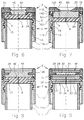
  • Figure 1 illustrates a side view of the biological liquid container and, in cross-sectional view, the safety closing device mounted on the container, wherein the cap and undercap are each formed by two portions closely joined with one another, according to a first embodiment of the invention
  • Figure 2 and 3 show the cap and the undercap, respectively, of the closing device of Figure 1, before their assembly on the container;
  • Figure 4 shows a second embodiment of the closing device of the invention; in particular, the central portion of the undercap extends in the inside of the container;
  • Figure 5 shows a third embodiment of the closing device of the invention; in particular, a different coupling system of the two portions is shows;
  • Figure 6 shows a fourth embodiment of the closing device of the invention; in particular, the central portion of the undercap is applied against the container through the insertion of a sheet made of an impermeable, perforable material;
  • Figure 7 shows a fifth embodiment of the closing device of the invention; in particular, the central portions of the cap and undercap are in the form of little cylinders;
  • Figure 8 shows a sixth embodiment of the closing device of the invention; in particular, the central portions of the cap and undercap have the same size and shape as each other;
  • Figure 9 shows a seventh embodiment of the closing device of the invention; in particular, the central portions of the cap and undercap are each formed by many pieces;
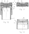
  • Figure 10 shows, in cross-sectional view, another embodiment of the safety closing device mounted on the container, wherein the cap and undercap are each formed by a single piece;
  • Figures 11 and 12 show the cap and undercap, respectively, of the closing device of Figure 10, before their assembly on the container;
  • Figure 13 is a cross-sectional view of the cap-undercap assembly before it is coupled with the container, wherein the external portion of the undercap is prearranged for being hooked to the container by a bayonet system, in accordance with a further embodiment of the invention;
  • Figure 14 is a bottom view of the cap-undercap assembly of Figure 13;
  • Figure 15 is a side view of the container before it is coupled with cap-undercap assembly of Figure 13;
  • Figure 16 is a plan view of the container of Figure 15;
  • Figure 17 shows the cap-undercap assembly of Figure 13, mounted on the container of Figure 15;
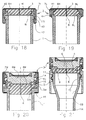
  • Figure 18 shows, in cross-sectional view, another embodiment of the safety closing device mounted on the container, wherein the external portion of the undercap is hooked to the edge of the container by a snapjoint;
  • Figure 19 shows, in cross-sectional view, another embodiment of the safety closing device mounted on the container, wherein the cap-undercap assembly is locked to the container by means of welding by fusion of an annular element of the undercap;
  • Figure 20 shows, in cross sectional view, a further embodiment of the safety closing device mounted on the container, wherein the cap-undercap assembly is locked to the container by means of a hose clamp;
  • Figure 21 shows the closing device of Figure 1, mounted on a container having a tapered opening;
  • Figure 22 shows a further embodiment of the closing device of the invention, wherein the central portion of the undercap is formed by a single piece having a zone with pre-established fracture and is coupled to the container by an annular sealing element;
  • Figure 23 shows the closing device of 22 before it is assembled on the container;
  • Figures 24 and 25 show two other embodiments of the annular sealing element of the closing device of Figure 22;
  • Figure 26 shows the closing device of Figure 22 mounted on a test tube having a tapered opening, wherein the cap is also formed by a single piece, and a graduated pipette is located over the test tube holding blood for the measurement of the blood erythrosedimentation rate (E.S.R.); and finally
  • Figure 27 shows the device of Figure 26 with the graduated pipette inserted into the test tube for the above mentioned measurement.
  • Referring first to Figs. 1, 2 and 3, by 1 it is indicated a cylindrical container for biological liquid, for example, blood, such as the test tube referred to herein, and by 2 and 3 the undercap and cap, respectively, forming the safety closing device, either assembled on the test tube (Fig. 1), or separated (Figs. 2 and 3) in accordance with the invention.
    Undercap 2 includes a central portion 4 and an external portion 5 closely joined to form a single piece; similarly, the cap 3 includes a central portion 6 and an external portion 7, also closely joined to form a single piece.
    The central portion 4 of undercap 2 has an incision 8 formed by two flexible edges that, in normal handling conditions of the test tube, fit perfectly together to avoid accidental leakage of the contained liquid.
    Many methods can be used to produce the incision 8; however, a preferred method comprises a cutting operation or the direct formation of the incision during the molding phase of the central portion. The execution of the incision can occur in a plane coinciding with or parallel to, or sloped with respect to the axis of the undercap.
    A coinciding or parallel incision obtained by cutting is preferred because the corresponding profile of flexible edges helps to seal the liquid held in the test tube.
    The internal central portions 4 and 6 perform the function of assuring the hermetic closing of the container, and therefore are made of a suitable elastic material and are axially tightened against the edge 9 of the test tube and the facing edge 10 of the undercap, respectively.
    On the other hand, the external portions 5 and 7 perform the function of assuring a mechanical coupling of the parts, by an axial tightening pressure and therefore are made by a suitable hard and strong plastic material.
    In detail, portion 5 includes a cylindrical axial wall 11 which is connected with the central portion 4 of the undercap and extends partially around the test tube 1 and the central portion 6.
    Portion 7 includes a cylindrical axial wall 12 which is connected with the central portion 6 of the cap.
    Walls 11 and 12 are provided with threads 14 and 16, having single or multiple starts, for their reciprocal engagement.
    Wall 11 also includes a thread 13 which engages with a thread 15 of the external wall of the test tube.
    Referring to the embodiment shown, the thread 14 is external to the wall 11, while thread 16 is internal to the wall 12.
    However, threads 14 and 16 could be formed in the inside and in the outside of the related walls, respectively.
    To achieve the hermetic closing of the container, the material forming the central portions 4 and 6 can be made of a rubber, preferably a bromine-buthylic, or a thermoplastic elastomer. In any case, a soft material for achesion to the edges 9 and 10 of the test tube and of the undercap when the cap and undercap are completely screwed together, is preferred. The material must also be perforable to permit easy access through it by, for example, a hypodermic needle during the drawing of the liquid in the test tube.
    The external portions 5 and 7 can be made of a thermoplastic resin or of another material harder than the material forming the central portions, in order to withstand the operations of screwing and unscrewing and above all, the final tightening operations of the cap and undercap.
    It is especially advantageous for the central portions 4 and 6 to be made of an injection moldable material, so that a co-molding or overmolding process to form the close connection with the external portions 5, 7 can be used.
    In order to guarantee a perfect connection and anchoring of these portions, the portions should include complementary engaging elements, such as protrusions and/or corresponding axial holes, that are reciprocally co-penetrated during the molding phase. In this manner, the two portions form one unit, separable only by breakage.
    In Figs. 1, 2 and 3, the materials of reciprocal co-penetration parts are designated by reference numerals 17 and 18. However, it is obvious that different types of reciprocal joints can be used to make the close connection of the parts during the co-molding phase.
    The above-shown closing device guarantees a hermetic sealing of the test tube so as to maintain the vacuum made inside before it was closed, or to assure perfect containment of the liquid sucked or anyhow introduced into the tube.
    Furthermore, the device allows the complete use of the volume of the test tube, as the bottom central portion 4 of the undercap does not extend or engage any internal space of the container.
    To increase closing safety, the threads 14 and 16 between the undercap 2 and cap 3, and the threads 13 and 15 between the undercap 2 and test tube 1, have opposite winding directions
    Preferably, the thread between the cap and undercap should be of a common clockwise type, because the extraction of the cap alone does not involve dangerous conditions, while the thread between the undercap and the test tube is of an unusual counterclockwise type, because unscrewing of the undercap involves potential dangerous conditions.
    This manner of closure has a double advantage; on the one hand, it avoids the accidental unscrewing of both parts when it is desired to extract only one, and on the other hand, it forcibly calls the operator's attention to the removal process.
    A further safety factor can be introduced by providing a condition of minimum force which must be exceeded to initiate the unscrewing of the undercap from the test tube.
    Further, due to the presence of the thread, the action of removing the undercap from the test tube does not involve a violent removing, and therefore the risk of blood spraying out of the test tube to contaminate the operator with blood vaporisation or aerosol formation is eliminated.
    Due to the threads used as axial tightening means, and also due to the opposite screwing direction and the minimum force which must be exceeded, it is guaranteed that an accidental opening of the test tube will definitely not occur.
    Therefore, in the closing device in accordance with the present invention, the risk of accidental discharge of contaminated blood or other biological liquid does not exist.
    As previously mentioned, it is absolutely required that the operator pay special attention during the opening of the test tube; in fact, the operator must intentionally make determined specific rotations of the cap and undercap.
    In order to avoid leakage of liquid between the facing surfaces of the central portions 4 and 6 at the moment in which the needle crosses these portions, during drawing of blood from the patient, these surfaces are suitably shaped to adhere perfectly with one another, at least in conjunction with the central zone, subject to the needle's passage. In this manner, no empty space in the intermediate zone is formed in which blood can be sucked during the passage of the hypodermic needle. For example, the coupled surfaces could assume a concave/convex form with contact surfaces in a curved or plane shape. The surface of the undercap should preferably be made in concave form, and, accordingly, the surface of the cap made in convex form as shown in Figures 1, 2 and 3.
    During the drawing of blood from a patient using, as said above, a double point hypodermic needle, the so-called "needle holder", one point is inserted into the blood vessel of the patient, and the other point extends through the portions 4 and 6 and into the inside of the test tube already under vacuum prior to closing.
    Under the effect of this vacuum, the blood is sucked into the test tube without the necessity for removing the cap 3 and undercap 2. Then the needle is extracted from the portions 4 and 6 and the blood remains inside the test tube for the time necessary with no possibility of leakage. Even when the cap 3 is removed, the passage of blood through the incision 8 is not possible as its flexible edges close perfectly after the extraction of the hypodermic needle.
    To make the necessary blood tests, the test tube can remain closed, and a simple device suitable for perforating the cap and undercap, can be used, or the cap 3 can be removed. The device for perforating and withdrawing the desired amount of liquid can be a point, pipette tip or any other device. The selected drawing device is inserted through the flexible edges of the incision 8 which separate to allow passage of the point therethrough.
    Once this operation is completed, the device is extracted and, if desired, the cap can be easily and safely screwed onto the undercap to restore the initial closing.
    Upon extracting the device from the incision 8, the flexible edges reclose perfectly so that even without screwing the cap back on the undercap, the blood, as said, cannot leak from the test tube. Therefore, any risk of contamination during drawing, analysis and/or transport of blood is eliminated.
    A further safety feature for preventing contact with the blood present in the test tube includes the elongation of the cylindrical wall 11 of the undercap by the wall 11a which surrounds the test tube and extends downward a certain lenght over the engagement zone with the same test tube so that its end 11b is sufficiently spaced from the internal surface 19 of the central portion 4 of the undercap 2.
    The extension of the wall 11a is related to the internal diameter of the test tube. If this diameter increases, the length of the extension increases. Therefore, when the undercap, for any reason, must be removed from the test tube, the chance of contact with the internal surface 19 of the undercap, is highly reduced, thereby avoiding the operator contact with parts contaminated with blood.
    The further Figs. 4 to 27 illustrate different embodiments related to the form and number of pieces forming the cap and undercap, and other embodiments of the axial tightening and coupling means of the components forming the closing device, and further possible applications of the device.
    In the above mentioned Figs. 4 to 27 identical parts have been indicated with the same identical reference symbols as those in Figs. 1 to 3, while the corresponding parts are indicated with the same reference symbols, followed by a capital letter.
    The device shown in Fig. 4 is identical to the device of Fig. 1, with the difference that the undercap 4A has a central axial extension 4' that is press-fitted into the opening 20 of the test tube 1. The lateral contact zone between extension 4' and opening 20 is indicated by numeral 21.
    Thus, the tightness is increased because a radial sealing on the zone 21 of the container is added to the axial sealing on the edge 9.
    As indicated by the dotted lines, the axial estension 4' can have a central hollow or cavity 22 at its end, to increase the internal available volume of the test tube.
    The closing device of Fig. 5 includes a cap 3 having an external portion formed by an elongated wall 12A which sealingly locks the portions 4B and 6B together and against the test tube 1. Indeed, wall 12A is engaged by the thread 13A with the thread 15 of the test tube compressing the central portion 6B of the cap 3 against the central portion 4B of the undercap 2 and this last portion against the edge 9 of the test tube.
    Like the embodiment of Figure 4, the central portion 4B includes an axial extension 4' pressed into the open end 20 of the test tube.
    In a manner similar to Figure 1, the central portion 6B is joined with the external portion 12A of the cap by a co-molding or overmolding process, while the central portion 4B of the undercap can form a separate molded piece.
    When a particularly elastic material is selected for portion 4B, in order to improve its handling and stiffening a ring 23 made of a more rigid material can be incorporated therein.
    The device shown in Fig. 6 has a central portion 4C and an external portion 5 of the undercap 2 joined with one another by a co-molding or overmolding process, as in the case of Figure 1, while the central portion 6C of the cap 3 forms a separate piece obtained by molding and is inserted into the related external portion 7C.
    As shown in the drawing, portions 6C and 7C of the cap have suitable joining shapes, wherein one portion (7C) can receive and elastically retain the other portion (6C), providing a tight mechanical connection.
    Further, a perforable sheet 24, of any impermeable, material, such as a polyethylene-lined aluminum sheet or non-polyethylene-lined aluminum sheet, is fixed, for example by glue, to the edge 9 between portion 4C and the test tube to assure a better vacuum of the test tube until the sheet is perforated by a needle or a similar device for drawing blood from or for introducing blood into the test tube.
    The closing device of Figure 7 includes central portions 4D and 6D for the undercap 2 and cap 3, respectively, formed by two perforable elements having a cylindrical shape. These elements can be obtained by molding or sheared from a sheet and then assembled during the assembly of the closing device. Locking of these elements with the test tube is obtained by the engagement of threads 13 and 15 and threads 14D and 16D which causes, by means of the internal edges 25 and 26 of the cap and undercap respectively, the tightening of the portions 6D and 4D against the edge of the test tube during the screwing movement of the external walls 11D and 12D.
    Wall 11D is coupled to the external wall of the test tube and to external wall 12D of cap by threads, as in the case of Figure 1, with the difference that thread 14D is internal to wall 11D and thread 16D is external to the wall 12D.
    The device of Figure 8 includes two cylinders 4E and 6E forming the central portions of the undercap 2 and cap 3. Because these cylinders are the same, used twice, there is a manufacturing advantage as they are produced separately and then elastically encased in the related internal annular edges 27 and 28 of the external walls 11E and 12E of the undercap and cap, respectively.
    Figure 9 shows the central portions of the cap and undercap, each formed of three pieces.
    The central portion 6F of the cap 3 is formed by three disks made of a perforable material obtained by molding or shearing and fixed afterwards, e.g. by glue, to one another and to the annular internal edge 28 of the external wall 7E. First, an external disk 29 can be affixed onto the edge 28 and then the intermediate disk 30, having a smaller diameter, can be affixed to the inside of the edge 28, and finally the other external disk 31 can be affixed onto the other side of the edge 28 and on the intermediate disk 30.
    Similarly, the central portion 4F of the undercap 2 which again includes incision 8, is formed by three disks 32, 33 and 34 fixed by the above mentioned method to the internal edge 27 of the wall 5E of the undercap.
    The closing device of Figure 10 is essentially similar to the closing device of Figure 1, but with the difference that the central and external portions 4G and 5G of the undercap 2 form a single unitary piece and the central and external portions 6G and 7G of the cap 3 are also formed of a single unitary piece. Figures 11 and 12 show the cap and undercap before assembly.
    In this embodiment, the material of the cap and undercap have characteristics suitable for assuring the flexibility and the perforability necessary for achieving perfect sealing and allowing the passage of a hypodermic needle therethrough, as well as being sufficiently strong to resist the screwing and unscrewing of the undercap and cap.
    A sole thermoplastic resin, such as polytetrafluoroethylene, polyethylene having a high or low density, polyethylene acetal resin, vulcanizable rubbers or thermoplastic elastomers of suitable hardeness, etc. can be used.
    It should be clear that only the undercap including both portions or only the cap including both portions could form an integral piece.
    The devices described so far, show that the locking means for mechanically coupling the cap to the undercap and the assembly thereof onto the test tube are formed by the threads 14, 16 (14D, 16D) and 13, 15 in the embodiments of Figures 1 to 4 and 6 to 12, and only by the threads 13A, 15 in the embodiment of Fig. 5, where the thread 13A is formed on the elongated external portion 12A of the cap 3.
    Furthermore, the locking of the cap-undercap assembly to the test tube is obtained by rotational movement.
    Another embodiment of the invention that also requires a rotational locking is shown in Figures 13 to 17.
    With reference to Figure 13, the undercap 2 is again made by a joint between the internal portion 4H and the external portion 7H, while the cap 3 is simply made of a sheet of an impermeable, perforable material 6H which is fixed for example by glue, to the edge 35 of the external portion 7H. The joint between the portions 4H, 7H is made similar to that shown in Figure 8, but it is clear that any other kind of joint is possible.
    To couple the cap-undercap assembly to the test tube 1, the wall 11H includes at its end some internal radial projections 36 having the form of circular sectors.
    As shown in Figure 17, the projections 36 engage with corresponding external radial projections 37, also made in the form of circular sectors, of the test tube 1.
    To close the test tube 1, the cap/undercap assembly is axially forced downward with the undercap's central elastic portion 4H, against the edge 9H of the test tube until the radial sectors 36 of the undercap overcome the espaces between the radial sectors 37 of the test tube. Then, the cap/undercap assembly is rotated until sectors 36, 37 are engaged.
    So, the coupling of this assembly to the test tube is produced by a bayonet joint and not by threads as in the preceding embodiments of the invention.
    Suitable rotation stop devices 38 and also anti-unscrewing devices 39 having desired disengaging force, can be provided on the external wall of the test tube and on the surmounting internal part of the undercap.
    The sheet of impermeable material 6H seals the closing device until the moment it is torn. Sealing is achieved by pressure applied between the external portion 7H and the internal elastic portion 4H, and between this elastic portion and the edge 9H of the test tube, and by the sheet 6H locked on the front side of the upper circular edge 35 of the undercap.
    In the embodiments shown in Figures 18, 19 and 20, the coupling of the cap-undercap assembly to the test tube is different from the coupling system of Figures 13 to 17.
    In particular, the devices of Figures 18 and 19 include a cap 3 again made of a sheet of an impermeable perforable material 6H as in the case of Figures 13 and 17, sealingly fixed to the edges 40 and 41 of the external portions 7I and 7L of the undercap 2, respectively, while the coupling of the cap-undercap assembly to the test tube 1 is obtained simply by an axial tightening action.
    The coupling of the cap-undercap assembly shown in Figure 18 is formed by a snap-joint between an internal circular edge 42 on the bottom end of the wall 11I and a corresponding external circular edge 43 of the test tube.
    The locking of the closing device occurs when the cap-undercap assembly is forced onto the end of the test tube until the edge 42 of the undercap passes over and engages the corresponding edge 43 of the test tube, while the central portion 4I of the undercap is simultaneously compressed against the edge 9I of the test tube.
    Figure 19 shows the connection of the cap-undercap assembly onto the test tube, again obtained by a compression, in particular the central portion 4L is compressed against the edge 9L of the test tube, but the irreversible coupling is obtained by fusion welding, e.g. by ultrasonic welding of an annular element 44, preferably having a triangular profile, shown on the face of the portion 7L extending toward the edge of the test tube. Element 44, for clarity's sake, is shown in figure 19 spaced from the edge 9L in an inoperative condition.
    As an alternative, element 44 can be placed on the edge 9L of the test tube facing a plane surface of the portion 7L.
    The element 44, fused to make a single piece between the undercap and test tube, is also known as an "ultrasonic wave lead".
    Figure 20 shows a device with a locking mechanism which is activated again by an axial tightening of the cap-undercap assembly against the edge 9M, but this tightening is made and maintained by a winding band 45. Band 45 winds completely around the closing device, engaging itself, on one side, with the top part of the cap 3 and, on the other side, with the external continuous circular edge 46 of the end 9M of the test tube.
    Band 45 can be a thermoshrinking plastic material, and, while the undercap 4M is kept compressed to the edge 9M, the band is submitted to, for example, hot air, and caused to axially shrink, locking the closing device onto the test tube in a hermetic condition.
    If the material of the band 45 is metallic or of any other suitable material, the sole variation would be the different techniques used for fastening the band.
    The central and external portions 4M and 5M of the undercap 2 and the similar portions 6M and 7M of the cap 3 are joined together by a co-molding or over-molding process, and the coupling between the cap and undercap is provided by a thread as in the case of Figure 1, but it is obvious that both the connection of these portions and the coupling between the cap and undercap could be made as shown in Figures 6 to 12.
    A closing system having a lever which acts directly on the cap and indirectly on the interposed undercap can be used. This system, known as an irreversible toggle, is widely known and used for containers of gaseous liquids or for hermetic sealing mainly for the storage of liquid and/or solid foodstuffs.
    In the embodiments shown in the Figures 13 to 20 the locking means for mechanically coupling the parts are as follows:
    • in Figures 13 to 17 these means are formed by the fastening means for joining the perforable sheet 6H (cap) to the portion 7H of the undercap and by the radial projections 36, 37 for securing the cap-undercap assembly to the container;
    • in Figure 18 these means are formed by the fastening means for joining the sheet 6H to the portion 7I and by the circular edges 42, 43 for securing the cap-undercap assembly to the container;
    • in Fig. 19 these means are formed by the fastening means for joining the sheet 6H to the portion 7L and by the annular weldable element 44 for securing the cap-undercap assembly to the container; and
    • in Fig. 20 these means are formed by threads between cap and undercap for coupling the cap to the undercap and by the winding band 45 for securing the assembly thereof to the container.
    Figure 21 illustrates a closing device different from the embodiment of Figure 1 in that the closing device is mounted on a container with tapered opening. In particular, the container is formed by a lower cylindrical part 1A, by an intermediate frusto-conical part 1B, and a superior part 1C, also cylindrical in shape, but having a diameter larger than the diameter of the lower part.
    The shape of the container is particularly suitable for test tubes used for holding blood of which the erythrosedimentation rate (E.S.R.) is to be measured.
    The closing devices shown in Figures 1 to 5 and 7 to 21 have the cap and undercap locked directly on the undercap and on the container, respectively. Further, the bottom of the undercap is prearranged for the introduction of a drilled rod-type element into the container, and includes the machining of a through incision 8 formed by flexible edges normally fitted together to form a liquid seal.
    Figures 22 to 27 show the undercap locked indirectly on the edge of the container and precisely with a sealing annular element disposed therebetween. Further, the above mentioned prearrangement on the bottom of the undercap is comprised of a zone with preestablished fracture, as described in the following.
    In detail, Figure 22 shows the annular sealing element formed by an elastic ring (O-ring) 47. Fig. 23 shows the annular element which is inserted in an annular groove 48 of the undercap 4P before the assembly of the closing device onto the container.
    The device of Figure 24 has the annular sealing element formed by a lower edge 47N of the undercap, having a triangular cross-section, while the device of Figure 25 includes an annular sealing comprised of a ring 47Q co-molded or over-molded or assembled onto the internal edge 49 of the undercap 4R.
    The use of an annular sealing element is particularly advantageous when using an undercap formed by a single piece as shown in Fig. 12. In this case, the material of the undercap should be selected to have only characteristics suitable for assuring the mechanical anchoring of the undercap to the cap and to the container, leaving the elastic annular element to perform the sealing function.
    Naturally, an elastic annular element could also be used for the sealing between the cap and undercap.
    Figures 22 to 25 show the bottom of the undercap including a central part 50 having a reduced thickness and provided with a circular tearing or pre-incision line 51, for establishing a preestablished fracture.
    In operation, after having removed the cap 3, a drilled rod-type element, such as a pipette or a tip of a pipette is pressed into the central part 50 to cause its partial or total separation from the bottom of the undercap 2, and the rod-type element can be further introduced into the inside of the container for blood drawing, etc.
    The zone with preestablished fracture can be also made by tearing or pre-incision lines converging towards the centre of part 50, i.e., located radially, so that the opening of the bottom is established by detaching or straddling the flexible engraved elements which close tightly after the pipette or tip is removed from the container.
    Figures 26 and 27 show another embodiment of the central part with preestablished fracture of the undercap. This central part identified by reference numeral 50A is produced by a tearing or preincision line 51A approximately circular in shape and extending slightly less than 360 degrees on the bottom of the undercap so that, after having pressed the drilled rod-type element on the part 50A, the said part is removed from the bottom providing the opening, but it remains connected to the bottom by a non-engraved appendix.
    In particular, the Figure 26 shows the closing device mounted on a test tube filled with blood of which the erythrosedimentation rate (E.S.R.) is to be measured using a graduated pipette 52 shown over the test tube prior to measurement.
    Figure 27 shows the graduated pipette inserted into the test tube, after having removed the cap, and the central pre-engraved part 50A is partially detached from the bottom of the undercap 4N.
    The execution of the erythrosedimentation rate (E.S.R.) is known and, for a detailed description, reference is made to European Patent No. 0 108 724.
    The embodiments of the Figures 21 to 27 show that the locking means to mechanically couple the cap to the undercap and the assembly thereof onto the test tube are the same ones shown in the embodiments of Figures 1 to 4 and 6 to 12.
    Satisfactory results are obtained with the use of plastic materials for both the cap and undercap, but it is clear that parts of these components, particularly the external portions could be made of different materials such as aluminum, various metals, thermoplastic or thermosetting resins, various fibers, etc..
    Finally, it should be noted that the different embodiments of the closing device according to the present invention, form a closed circuit system by which operations involving blood (filling of test tubes, access to its inside, blood drawing, etc.) occur in such a way as to completely avoid the operator coming in contact with the liquid.

    Claims (3)

    1. A closing device for a container (1, 1A) suitable to include a biological liquid, comprising an undercap (2) including a central portion (4, 4A-4N) being pierceable and a cap (3) including a central portion (6, 6A-6M) being pierceable, wherein
      the undercap is sealingly connectable to an open end of the container and the cap is sealingly connectable to the undercap by engaging means (12-16) provided at said container, said undercap and said cap,
      said engaging means (12-16) include rotationally removable locking means (14, 16) provided at said undercap (2) and said cap (3) for mechanically and axially fixing the cap on the undercap,
      said central portions (4, 4A-4N; 6, 6A-6N) of said undercap and said cap are made of elastic material, and
      the contact surfaces of the central portions are suitably shaped to adhere to one another, when said cap is fixed on said undercap by said locking means,
      characterised in that
      the central portion (4, 4A, 4B, 4C, 4D, 4E, 4F, 4G) of said undercap (2) includes a through slit or an incision (8) having flexible edges being openable, and
      said undercap has an external portion made of hard plastic.
    2. A closing device according to claim 1, wherein the central portions and external portions include reciprocal copenetrating parts (18a, 18) for connecting the elastic material of the central portions to the hard plastic material of the external portions and wherein the copenetrating parts completely anchor the central portions and external portions.
    3. A closing device according to claims 1 and 2, wherein the central portions of the undercap (2) and/or the cap (3) includes at least two separate parts formed by moulding or shearing, said at least two separate parts being adhered to each other and sealingly assembled with the external portions.
    EP93107267A 1992-05-13 1993-05-05 Safety closing device for biological liquid containers Expired - Lifetime EP0569835B1 (en)

    Applications Claiming Priority (2)

    Application Number Priority Date Filing Date Title
    ITMI921139 1992-05-13
    IT92MI1139 IT1274578B (en) 1992-05-13 1992-05-13 SAFETY CLOSURE DEVICE FOR CONTAINERS FOR ORGANIC LIQUIDS

    Publications (2)

    Publication Number Publication Date
    EP0569835A1 EP0569835A1 (en) 1993-11-18
    EP0569835B1 true EP0569835B1 (en) 1998-09-02

    Family

    ID=11363273

    Family Applications (1)

    Application Number Title Priority Date Filing Date
    EP93107267A Expired - Lifetime EP0569835B1 (en) 1992-05-13 1993-05-05 Safety closing device for biological liquid containers

    Country Status (15)

    Country Link
    US (1) US5433716A (en)
    EP (1) EP0569835B1 (en)
    JP (1) JPH06509015A (en)
    KR (1) KR970010165B1 (en)
    AT (1) ATE170428T1 (en)
    AU (1) AU678551B2 (en)
    CA (1) CA2112985A1 (en)
    DE (1) DE69320686T2 (en)
    DK (1) DK0569835T3 (en)
    ES (1) ES2121889T3 (en)
    IL (1) IL105627A (en)
    IT (1) IT1274578B (en)
    MX (1) MX9302779A (en)
    TW (1) TW252050B (en)
    WO (1) WO1993023165A1 (en)

    Cited By (2)

    * Cited by examiner, † Cited by third party
    Publication number Priority date Publication date Assignee Title
    ITPD20080334A1 (en) * 2008-11-14 2010-05-15 Holos Sro ANTI-TAMPER CLOSING CAP FOR TUBES
    US11369296B2 (en) 2011-02-01 2022-06-28 Olberon Medical Innovation Sas Needle holder

    Families Citing this family (42)

    * Cited by examiner, † Cited by third party
    Publication number Priority date Publication date Assignee Title
    US5494170A (en) * 1993-05-06 1996-02-27 Becton Dickinson And Company Combination stopper-shield closure
    US5458113A (en) * 1994-08-12 1995-10-17 Becton Dickinson And Company Collection assembly
    DE19615422A1 (en) 1996-04-19 1997-11-20 Boehringer Ingelheim Kg Two-chamber cartridge for propellant-free MDIs
    US6161712A (en) 1996-07-22 2000-12-19 Becton Dickinson And Company Ball and socket closure
    NL1003726C2 (en) 1996-08-01 1998-02-05 Micronic B V Test tube with optically readable coding.
    US6017317A (en) * 1997-03-26 2000-01-25 Becton Dickinson And Company Assembly for collecting blood or other body fluids
    US5948364A (en) * 1997-09-12 1999-09-07 Becton Dickinson & Company Ball and socket closure for specimen collection container
    US5919420A (en) * 1997-09-12 1999-07-06 Becton Dickinson And Company Ball and socket closure for specimen collection container incorporating a resilient elastomeric seal
    US6350415B1 (en) 1997-09-12 2002-02-26 Becton, Dickinson And Company Ball and socket closure for specimen collection container incorporating a dimple locking mechanism
    US6032813A (en) * 1997-09-12 2000-03-07 Becton, Dickinson And Company Ball and socket closure for specimen collection container incorporating an integral flexible seal
    USD422712S (en) * 1997-09-12 2000-04-11 Becton, Dickinson And Company Closure for specimen collection container
    US6165138A (en) * 1998-09-30 2000-12-26 Becton Dickinson And Company Self-sealing closure for a medical speciman collection container
    DE19851404A1 (en) 1998-11-07 2000-05-11 Boehringer Ingelheim Int Pressure compensation device for a double tank
    US6716396B1 (en) * 1999-05-14 2004-04-06 Gen-Probe Incorporated Penetrable cap
    USD457247S1 (en) 2000-05-12 2002-05-14 Gen-Probe Incorporated Cap
    ATE457200T1 (en) * 2001-03-09 2010-02-15 Gen Probe Inc PERMEABLE HOOD
    US20030052074A1 (en) * 2001-09-17 2003-03-20 Chang Min Shuan Closure for container for holding biological samples
    AU2003226075B2 (en) 2002-04-12 2008-09-25 Instrumentation Laboratory Company Immunoassay probe
    US6994699B2 (en) * 2002-06-12 2006-02-07 Baxter International Inc. Port, a container and a method for accessing a port
    TWI303565B (en) * 2002-08-16 2008-12-01 Glaxosmithkline Biolog Sa Closure system,vial having the closure system,method of closing a vial,method of filling a pharmaceutical vial, and vial closure
    DE10254441A1 (en) * 2002-11-21 2004-06-09 Tecpharma Licensing Ag Cannula holder comprises a screw thread turning in a first direction, and an opposite-handed screw thread turning in a second direction
    US8303914B2 (en) 2003-01-06 2012-11-06 Becton, Dickinson And Company Tube closure with removable septum for direct instrument access
    DE10331678A1 (en) * 2003-07-14 2005-02-10 Andreas Hettich Gmbh & Co. Kg Closure device for a centrifuge tube
    US20060036231A1 (en) * 2004-05-27 2006-02-16 Conard William A Injection port and method of making the same
    US8211386B2 (en) 2004-06-08 2012-07-03 Biokit, S.A. Tapered cuvette and method of collecting magnetic particles
    US8387810B2 (en) * 2007-04-16 2013-03-05 Becton, Dickinson And Company Pierceable cap having piercing extensions for a sample container
    US8387811B2 (en) 2007-04-16 2013-03-05 Bd Diagnostics Pierceable cap having piercing extensions
    US20090196798A1 (en) 2008-02-06 2009-08-06 Robert Sassa Barrier with Low Extractables and Resealing Properties
    FR2949260B1 (en) * 2009-08-21 2013-07-05 Eurl Jean Mainguet SAMPLE COLLECTION DEVICE FOR PRODUCTS, ESPECIALLY CHEMICALS
    JP2014513794A (en) 2011-04-22 2014-06-05 スリーエム イノベイティブ プロパティズ カンパニー Luminescence detection method
    US20140038228A1 (en) * 2011-04-22 2014-02-06 3M Innovative Properties Company Removable layer and method of use
    US9743660B2 (en) * 2011-06-22 2017-08-29 Rich Technologies Holding Company, Llc System, method, and device for preserving blood or its components in gas medium under pressure
    ITMI20121793A1 (en) * 2012-10-23 2014-04-24 Copan Italia Spa CLOSING ELEMENT OF A CONTAINER FOR BIOLOGICAL FLUIDS
    EP2962760A1 (en) * 2014-07-01 2016-01-06 Büchi Labortechnik AG Cup closure for closing a process vessel
    DE102014110327B4 (en) 2014-07-22 2016-02-11 App Biomaterials Gmbh Closure for pharmaceutical containers and method for closing a vial
    US10399751B2 (en) * 2016-06-21 2019-09-03 Coravin, Inc. Beverage container cap for use with beverage extractor
    KR102672435B1 (en) 2017-03-03 2024-06-07 리치 테크놀로지스 홀딩 컴퍼니 엘엘씨 Device for preserving blood products and cell cultures in gaseous media under pressure
    DE102017124840B3 (en) * 2017-10-24 2018-12-13 Testo SE & Co. KGaA Incubator, sample container, kit and method for assaying a sample material
    DE102019117411A1 (en) * 2019-06-27 2020-12-31 Testo SE & Co. KGaA Sample container and use of a sample container
    WO2021209755A1 (en) * 2020-04-15 2021-10-21 Bjs Ip Ltd A cap for a pathogen sample tube
    CN112619718B (en) * 2020-11-17 2022-06-14 浙江省海洋水产研究所 Exempt from to uncap centrifuging tube
    CN113181546B (en) * 2021-04-29 2022-08-02 曲靖市第一人民医院 Hemodialysis pipe tip locking structure

    Family Cites Families (21)

    * Cited by examiner, † Cited by third party
    Publication number Priority date Publication date Assignee Title
    CA770450A (en) * 1967-10-31 J. Hailes Norman Tamper proof bottle cap
    US2364126A (en) * 1941-12-09 1944-12-05 Cantor Abraham Receptacle closure
    US2487728A (en) * 1947-06-10 1949-11-08 Fabian L Quiring Cap for poison containers
    US2960247A (en) * 1958-03-10 1960-11-15 J T Olson Container safety closure
    US3269576A (en) * 1965-03-02 1966-08-30 William J H Law Safety closure for containers
    GB1294165A (en) * 1970-08-05 1972-10-25 P C Cox Mastic Appliances Ltd Screw threaded container closures
    US3734332A (en) * 1971-12-01 1973-05-22 N Grulich Safety closure
    US3844437A (en) * 1972-07-18 1974-10-29 Connor J O Safety closure
    US3950917A (en) * 1973-03-07 1976-04-20 American Hospital Supply Corporation Method of opening a double screw cap system for sterile medical container
    US3827593A (en) * 1973-03-16 1974-08-06 K I C Inc Container safety closure
    US4204606A (en) * 1975-03-21 1980-05-27 Dematex Development & Investment Establishment Tube and stopper combination with venting structure
    FI66807C (en) * 1977-05-09 1984-12-10 Asicomo As CAPSULE FOR BEHAOLLARLOCK AND FOAR FARANDE FOER TILLVERKNING AV DETSAMMA
    US4243150A (en) * 1978-01-23 1981-01-06 Siemens Aktiengesellschaft Bottle seal
    GB2034289A (en) * 1978-11-18 1980-06-04 Ryford Ltd Improvements Relating to Screw-capped Containers
    AT379069B (en) * 1984-01-11 1985-11-11 Greiner & Soehne C A BLOOD SAMPLES
    US4753358A (en) * 1987-03-02 1988-06-28 Promega Corporation Vial cap coupling device
    JPH04501994A (en) * 1988-11-28 1992-04-09 ジョセフ パーソンズ ノミニーズ プロプライエタリー リミテッド cap
    JPH02212768A (en) * 1989-02-13 1990-08-23 Terumo Corp Blood sampling tube
    IT215743Z2 (en) * 1989-03-03 1990-11-05 Instrumentation Lab Spa SAMPLE CUVET WITH WELDED CAP.
    IT1229165B (en) * 1989-04-07 1991-07-22 Leopardi Francesco Paoletti Se DEVICE FOR CLOSING VACUUM TUBES FOR BLOOD COLLECTION.
    CA2015571A1 (en) * 1990-04-26 1991-10-26 Samco Scientific, Inc. Reinsertable closure for sample tubes

    Cited By (2)

    * Cited by examiner, † Cited by third party
    Publication number Priority date Publication date Assignee Title
    ITPD20080334A1 (en) * 2008-11-14 2010-05-15 Holos Sro ANTI-TAMPER CLOSING CAP FOR TUBES
    US11369296B2 (en) 2011-02-01 2022-06-28 Olberon Medical Innovation Sas Needle holder

    Also Published As

    Publication number Publication date
    AU4087493A (en) 1993-12-13
    MX9302779A (en) 1993-11-01
    IL105627A (en) 1996-05-14
    KR940701301A (en) 1994-05-28
    DE69320686T2 (en) 1999-04-01
    DK0569835T3 (en) 1999-05-31
    ITMI921139A1 (en) 1993-11-13
    AU678551B2 (en) 1997-06-05
    KR970010165B1 (en) 1997-06-21
    US5433716A (en) 1995-07-18
    DE69320686D1 (en) 1998-10-08
    EP0569835A1 (en) 1993-11-18
    ATE170428T1 (en) 1998-09-15
    WO1993023165A1 (en) 1993-11-25
    IT1274578B (en) 1997-07-17
    ES2121889T3 (en) 1998-12-16
    CA2112985A1 (en) 1993-11-25
    ITMI921139A0 (en) 1992-05-13
    JPH06509015A (en) 1994-10-13
    TW252050B (en) 1995-07-21

    Similar Documents

    Publication Publication Date Title
    US5433716A (en) Safety closing device for biological liquid containers
    KR100856772B1 (en) Urine Specimen Container and How to Use It
    CA2658388C (en) Cap assembly and container used therewith
    US8132685B2 (en) Two-part closure for a container
    JPH0738155Y2 (en) Container assembly
    US5061263A (en) Liquid collection tube
    JP4448446B2 (en) Vial closure system, vial, vial sealing and filling method, and vial stand
    US6145688A (en) Closure device for containers
    EP0257498B1 (en) Rubber/plastic stopper composite with mechanical adhesive joints
    RU2692035C2 (en) Container cover
    EP0837008A1 (en) Crown-shaped lid of drug container
    US4463862A (en) Thermoplastic container
    CA2005732C (en) Liquid collecting tube
    US20080093364A1 (en) Reagent closure
    WO2017201370A1 (en) Specimen container for urine and other liquids
    JPH11314657A (en) Cap for container of centrifugal separator
    GB1588794A (en) Closure means
    CA1052732A (en) Closable sterile container
    AU2005209675B2 (en) Two-part closure for a container
    JP2001247149A (en) Container cap
    AU634468B2 (en) Medical fail safe releasible locks and/or seals for capped disposable centrifuge containers, cryogenic vials and the like
    JPH02269966A (en) Liquid sampling tube
    MXPA95001294A (en) Method to produce packing media for medical products as contact lenses in particular sua contact lenses

    Legal Events

    Date Code Title Description
    PUAI Public reference made under article 153(3) epc to a published international application that has entered the european phase

    Free format text: ORIGINAL CODE: 0009012

    AK Designated contracting states

    Kind code of ref document: A1

    Designated state(s): AT BE CH DE DK ES FR GB GR IE IT LI LU MC NL PT SE

    17P Request for examination filed

    Effective date: 19930923

    17Q First examination report despatched

    Effective date: 19950314

    RAP1 Party data changed (applicant data changed or rights of an application transferred)

    Owner name: HEISENBERG FINANCE S.A.

    GRAG Despatch of communication of intention to grant

    Free format text: ORIGINAL CODE: EPIDOS AGRA

    GRAG Despatch of communication of intention to grant

    Free format text: ORIGINAL CODE: EPIDOS AGRA

    GRAH Despatch of communication of intention to grant a patent

    Free format text: ORIGINAL CODE: EPIDOS IGRA

    GRAH Despatch of communication of intention to grant a patent

    Free format text: ORIGINAL CODE: EPIDOS IGRA

    GRAA (expected) grant

    Free format text: ORIGINAL CODE: 0009210

    AK Designated contracting states

    Kind code of ref document: B1

    Designated state(s): AT BE CH DE DK ES FR GB GR IE IT LI LU MC NL PT SE

    REF Corresponds to:

    Ref document number: 170428

    Country of ref document: AT

    Date of ref document: 19980915

    Kind code of ref document: T

    REG Reference to a national code

    Ref country code: CH

    Ref legal event code: EP

    REF Corresponds to:

    Ref document number: 69320686

    Country of ref document: DE

    Date of ref document: 19981008

    REG Reference to a national code

    Ref country code: IE

    Ref legal event code: FG4D

    REG Reference to a national code

    Ref country code: CH

    Ref legal event code: NV

    Representative=s name: E. BLUM & CO. PATENTANWAELTE

    REG Reference to a national code

    Ref country code: ES

    Ref legal event code: FG2A

    Ref document number: 2121889

    Country of ref document: ES

    Kind code of ref document: T3

    ET Fr: translation filed
    REG Reference to a national code

    Ref country code: PT

    Ref legal event code: SC4A

    Free format text: AVAILABILITY OF NATIONAL TRANSLATION

    Effective date: 19981111

    PG25 Lapsed in a contracting state [announced via postgrant information from national office to epo]

    Ref country code: LU

    Free format text: LAPSE BECAUSE OF NON-PAYMENT OF DUE FEES

    Effective date: 19990505

    REG Reference to a national code

    Ref country code: DK

    Ref legal event code: T3

    PLBE No opposition filed within time limit

    Free format text: ORIGINAL CODE: 0009261

    26N No opposition filed
    PG25 Lapsed in a contracting state [announced via postgrant information from national office to epo]

    Ref country code: MC

    Free format text: LAPSE BECAUSE OF NON-PAYMENT OF DUE FEES

    Effective date: 19991130

    PGFP Annual fee paid to national office [announced via postgrant information from national office to epo]

    Ref country code: IE

    Payment date: 20010412

    Year of fee payment: 9

    PGFP Annual fee paid to national office [announced via postgrant information from national office to epo]

    Ref country code: PT

    Payment date: 20010419

    Year of fee payment: 9

    Ref country code: DK

    Payment date: 20010419

    Year of fee payment: 9

    PGFP Annual fee paid to national office [announced via postgrant information from national office to epo]

    Ref country code: GR

    Payment date: 20010420

    Year of fee payment: 9

    PGFP Annual fee paid to national office [announced via postgrant information from national office to epo]

    Ref country code: CH

    Payment date: 20010430

    Year of fee payment: 9

    PGFP Annual fee paid to national office [announced via postgrant information from national office to epo]

    Ref country code: SE

    Payment date: 20010502

    Year of fee payment: 9

    PGFP Annual fee paid to national office [announced via postgrant information from national office to epo]

    Ref country code: BE

    Payment date: 20010507

    Year of fee payment: 9

    PGFP Annual fee paid to national office [announced via postgrant information from national office to epo]

    Ref country code: AT

    Payment date: 20010523

    Year of fee payment: 9

    PGFP Annual fee paid to national office [announced via postgrant information from national office to epo]

    Ref country code: NL

    Payment date: 20010531

    Year of fee payment: 9

    PGFP Annual fee paid to national office [announced via postgrant information from national office to epo]

    Ref country code: GB

    Payment date: 20011003

    Year of fee payment: 9

    REG Reference to a national code

    Ref country code: GB

    Ref legal event code: IF02

    PG25 Lapsed in a contracting state [announced via postgrant information from national office to epo]

    Ref country code: GB

    Free format text: LAPSE BECAUSE OF NON-PAYMENT OF DUE FEES

    Effective date: 20020505

    Ref country code: AT

    Free format text: LAPSE BECAUSE OF NON-PAYMENT OF DUE FEES

    Effective date: 20020505

    PG25 Lapsed in a contracting state [announced via postgrant information from national office to epo]

    Ref country code: SE

    Free format text: LAPSE BECAUSE OF NON-PAYMENT OF DUE FEES

    Effective date: 20020506

    Ref country code: IE

    Free format text: LAPSE BECAUSE OF NON-PAYMENT OF DUE FEES

    Effective date: 20020506

    PG25 Lapsed in a contracting state [announced via postgrant information from national office to epo]

    Ref country code: LI

    Free format text: LAPSE BECAUSE OF NON-PAYMENT OF DUE FEES

    Effective date: 20020531

    Ref country code: DK

    Free format text: LAPSE BECAUSE OF NON-PAYMENT OF DUE FEES

    Effective date: 20020531

    Ref country code: CH

    Free format text: LAPSE BECAUSE OF NON-PAYMENT OF DUE FEES

    Effective date: 20020531

    Ref country code: BE

    Free format text: LAPSE BECAUSE OF NON-PAYMENT OF DUE FEES

    Effective date: 20020531

    PG25 Lapsed in a contracting state [announced via postgrant information from national office to epo]

    Ref country code: PT

    Free format text: LAPSE BECAUSE OF NON-PAYMENT OF DUE FEES

    Effective date: 20021130

    PG25 Lapsed in a contracting state [announced via postgrant information from national office to epo]

    Ref country code: NL

    Free format text: LAPSE BECAUSE OF NON-PAYMENT OF DUE FEES

    Effective date: 20021201

    PG25 Lapsed in a contracting state [announced via postgrant information from national office to epo]

    Ref country code: GR

    Free format text: LAPSE BECAUSE OF NON-PAYMENT OF DUE FEES

    Effective date: 20021206

    GBPC Gb: european patent ceased through non-payment of renewal fee

    Effective date: 20020505

    REG Reference to a national code

    Ref country code: DK

    Ref legal event code: EBP

    EUG Se: european patent has lapsed
    REG Reference to a national code

    Ref country code: CH

    Ref legal event code: PL

    NLV4 Nl: lapsed or anulled due to non-payment of the annual fee

    Effective date: 20021201

    REG Reference to a national code

    Ref country code: PT

    Ref legal event code: MM4A

    Free format text: LAPSE DUE TO NON-PAYMENT OF FEES

    Effective date: 20021130

    REG Reference to a national code

    Ref country code: IE

    Ref legal event code: MM4A

    PGFP Annual fee paid to national office [announced via postgrant information from national office to epo]

    Ref country code: ES

    Payment date: 20070426

    Year of fee payment: 15

    PGFP Annual fee paid to national office [announced via postgrant information from national office to epo]

    Ref country code: DE

    Payment date: 20070523

    Year of fee payment: 15

    PGFP Annual fee paid to national office [announced via postgrant information from national office to epo]

    Ref country code: FR

    Payment date: 20070419

    Year of fee payment: 15

    REG Reference to a national code

    Ref country code: FR

    Ref legal event code: ST

    Effective date: 20090119

    PG25 Lapsed in a contracting state [announced via postgrant information from national office to epo]

    Ref country code: FR

    Free format text: LAPSE BECAUSE OF NON-PAYMENT OF DUE FEES

    Effective date: 20080602

    Ref country code: DE

    Free format text: LAPSE BECAUSE OF NON-PAYMENT OF DUE FEES

    Effective date: 20081202

    REG Reference to a national code

    Ref country code: ES

    Ref legal event code: FD2A

    Effective date: 20080506

    PG25 Lapsed in a contracting state [announced via postgrant information from national office to epo]

    Ref country code: ES

    Free format text: LAPSE BECAUSE OF NON-PAYMENT OF DUE FEES

    Effective date: 20080506

    PGFP Annual fee paid to national office [announced via postgrant information from national office to epo]

    Ref country code: IT

    Payment date: 20100519

    Year of fee payment: 18

    PG25 Lapsed in a contracting state [announced via postgrant information from national office to epo]

    Ref country code: IT

    Free format text: LAPSE BECAUSE OF NON-PAYMENT OF DUE FEES

    Effective date: 20110505