EP0569609A1 - Defibrillator - Google Patents
Defibrillator Download PDFInfo
- Publication number
- EP0569609A1 EP0569609A1 EP92107996A EP92107996A EP0569609A1 EP 0569609 A1 EP0569609 A1 EP 0569609A1 EP 92107996 A EP92107996 A EP 92107996A EP 92107996 A EP92107996 A EP 92107996A EP 0569609 A1 EP0569609 A1 EP 0569609A1
- Authority
- EP
- European Patent Office
- Prior art keywords
- current
- defibrillator
- charging
- electrodes
- resistor
- Prior art date
- Legal status (The legal status is an assumption and is not a legal conclusion. Google has not performed a legal analysis and makes no representation as to the accuracy of the status listed.)
- Granted
Links
Images
Classifications
-
- A—HUMAN NECESSITIES
- A61—MEDICAL OR VETERINARY SCIENCE; HYGIENE
- A61N—ELECTROTHERAPY; MAGNETOTHERAPY; RADIATION THERAPY; ULTRASOUND THERAPY
- A61N1/00—Electrotherapy; Circuits therefor
- A61N1/18—Applying electric currents by contact electrodes
- A61N1/32—Applying electric currents by contact electrodes alternating or intermittent currents
- A61N1/38—Applying electric currents by contact electrodes alternating or intermittent currents for producing shock effects
- A61N1/39—Heart defibrillators
- A61N1/3918—Heart defibrillators characterised by shock pathway, e.g. by electrode configuration
-
- A—HUMAN NECESSITIES
- A61—MEDICAL OR VETERINARY SCIENCE; HYGIENE
- A61N—ELECTROTHERAPY; MAGNETOTHERAPY; RADIATION THERAPY; ULTRASOUND THERAPY
- A61N1/00—Electrotherapy; Circuits therefor
- A61N1/18—Applying electric currents by contact electrodes
- A61N1/32—Applying electric currents by contact electrodes alternating or intermittent currents
- A61N1/38—Applying electric currents by contact electrodes alternating or intermittent currents for producing shock effects
- A61N1/39—Heart defibrillators
- A61N1/3925—Monitoring; Protecting
- A61N1/3931—Protecting, e.g. back-up systems
-
- A—HUMAN NECESSITIES
- A61—MEDICAL OR VETERINARY SCIENCE; HYGIENE
- A61N—ELECTROTHERAPY; MAGNETOTHERAPY; RADIATION THERAPY; ULTRASOUND THERAPY
- A61N1/00—Electrotherapy; Circuits therefor
- A61N1/18—Applying electric currents by contact electrodes
- A61N1/32—Applying electric currents by contact electrodes alternating or intermittent currents
- A61N1/38—Applying electric currents by contact electrodes alternating or intermittent currents for producing shock effects
- A61N1/39—Heart defibrillators
- A61N1/3906—Heart defibrillators characterised by the form of the shockwave
- A61N1/3912—Output circuitry therefor, e.g. switches
-
- Y—GENERAL TAGGING OF NEW TECHNOLOGICAL DEVELOPMENTS; GENERAL TAGGING OF CROSS-SECTIONAL TECHNOLOGIES SPANNING OVER SEVERAL SECTIONS OF THE IPC; TECHNICAL SUBJECTS COVERED BY FORMER USPC CROSS-REFERENCE ART COLLECTIONS [XRACs] AND DIGESTS
- Y10—TECHNICAL SUBJECTS COVERED BY FORMER USPC
- Y10S—TECHNICAL SUBJECTS COVERED BY FORMER USPC CROSS-REFERENCE ART COLLECTIONS [XRACs] AND DIGESTS
- Y10S128/00—Surgery
- Y10S128/908—Patient protection from electric shock
Definitions
- the invention relates to a defibrillator with a charging capacity, which can be switched on both sides for charging to a charging circuit and can be connected via a switching device to at least two electrodes arranged in the region of the heart for defibrillating a heart.
- Such a defibrillator is intended for implantation in the body of a patient.
- the known defibrillator contains a charging capacity consisting of two capacitors which are connected to a charging circuit for charging to a predetermined voltage.
- the two capacitors are also connected via a switching device consisting of four switches arranged in a bridge circuit to two electrodes placed on the heart of the patient.
- the charging capacity is first charged to the predetermined voltage and then connected to the electrodes on the heart via the switching device, so that the charging capacity is discharged via the heart tissue with a discharge current.
- the discharge current through the cardiac tissue is divided into a plurality of successive partial currents with alternating current directions.
- the current through the heart tissue that causes defibrillation is dependent on the charging voltage of the charging capacity and the electrical resistance of the heart tissue between the electrodes. At the beginning of the discharge of the charging capacity, the current is at its highest value and then decays exponentially. For effective defibrillation of the heart, the current through the heart tissue must exceed a certain minimum value for a certain duration. For this reason, the charging voltage for the charging capacity is selected so that the current at the start of the discharge process is sufficiently large to drop below the minimum value only after the specific duration has elapsed. The portion of the current that exceeds the minimum value is not only of no use in terms of effective defibrillation, but can also lead to damage to the heart tissue due to the high initial value.
- the invention is therefore based on the object of preventing the development of excessively high discharge currents in a defibrillator, but without the effectiveness of the defibrillation being influenced thereby.
- the object is achieved in that a device for limiting the current to a predetermined maximum value is arranged in the defibrillator of the type specified in the current path from the charging capacity to the electrodes. This ensures that during normal operation of the defibrillator, the discharge current of the charging capacity and thus the current through the heart tissue is limited to the predetermined maximum value, so that damage to the heart tissue is excluded is.
- the same current limitation is also effective in the event of a fault, for example a short circuit between the electrodes, so that damage to the defibrillator is prevented.
- a structurally particularly simple and space-saving design of the device for current limitation is achieved in that it consists of a resistance element with positive temperature characteristics (PTC resistor).
- PTC resistor positive temperature characteristics
- Such a resistance element which usually consists of a semiconducting ceramic, increases its resistance value with increasing temperature due to the current flowing through the resistance element, as a result of which the current is limited.
- Resistance elements made of semiconducting polymer have been known for some time, which act as self-healing fuses by abruptly increasing their resistance value at a specific temperature value which corresponds to a specific current and thus causing a current interruption until the temperature has dropped below the specified value. If only protection against possible short circuits is desired in the defibrillator according to the invention, such a resistance element is of particular advantage because of its fast response speed.
- the device for current limitation has a low-impedance measuring resistor arranged in the current path, that a measuring circuit that detects the voltage drop caused by the current in the measuring resistor is parallel to the measuring resistor and that the measuring circuit on the output side at the control input of a controllable resistor or switch is connected, either in series with the Measuring resistor is arranged in the current path and is controlled in a higher-impedance or open state when the maximum value for the current is reached, or is arranged in a current branch parallel to the charging capacity and controlled in a lower-impedance or closed state when the maximum value for the current is reached becomes.
- the current limitation is independent of any temperature compensation processes and is therefore particularly quick and accurate. It is also possible to set different values for the maximum value of the current to be limited by changing the control behavior of the measuring circuit.
- the current limitation provided according to the invention proves to be particularly advantageous if, in the case of the defibrillator, the charging circuit, the charging capacity and the switching device are arranged in a housing which can be implanted in the body of a patient. Since after an implantation of such a defibrillator, the electrode leads and electrodes are no longer easily accessible, there is a particularly great need for a current limitation in the event that the electrode leads or electrodes change their position in the patient's body and can thus cause short circuits.
- the device for current limitation is preferably arranged in the housing, so that the current limitation takes place regardless of the point at which a possible short circuit occurs in the electrode lines. However, there is also the possibility of arranging the current limiting device in an electrode feed line with appropriate insulation of the electrode feed lines.
- the device for current limitation is arranged in a plug part which is provided with connecting elements for connection to the housing of the defibrillator and with further connecting elements for connecting at least one of the electrodes.
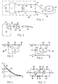
- the defibrillator shown as a block diagram in FIG. 1 contains a voltage source 1 in the form of a battery, which is connected to a charging circuit 2 for a charging capacity 3.
- the charging circuit 2 generates at its output connections 4 and 5 a predetermined charging voltage to which the charging capacitance 3 is charged when it is connected to the output connections 4 and 5 on both sides 6 and 7 thereof via two controllable switches 8 and 9.
- the two sides 6 and 7 of the loading capacity 3 are also provided by a controllable switching device from two further switches 10 and 11, each with two electrode connections 12 and 13, to which two electrodes 17 and 18, which are arranged in the region of the heart 16 of a patient, are connected via an electrode line 14 and 15, respectively.
- a resistance element 19 with a positive temperature characteristic is arranged between the controllable switch 10 and the electrode connection 12.
- the resistance value of the resistance element 19 increases markedly due to the temperature rise in the resistance element 19 and in this way limits or interrupts the current through the resistance element 19 in the case of the semiconducting polymer it is ensured that in the event of a short circuit between the electrode lines 14 and 15 or the electrodes 17 and 18, the discharge current of the discharge capacitance 3 is limited to the predetermined maximum value.
- FIG. 1 shows only the parts of the defibrillator that are essential for understanding the invention.
- the circuit parts that are required to control the switches 8 to 11 and to control the charging circuit 2 for the purpose of setting the predetermined charging voltage for the charging capacity 3 are not shown.
- the charging capacity 3 can consist of several capacitors and the controllable switching device 10, 11, as in the case of the defibrillator known from the above-mentioned US Pat 16 can flow through.
- the electrodes 17 and 18 can be designed as surface electrodes or as catheter electrodes and can be arranged outside or in the heart 16. Further electrodes can also be provided which are connected to the electrodes 17 and 18 shown.
- the battery 1, the charging circuit 2, the charging capacity 3, the controllable switches 8 to 11 and the current-limiting resistance element 19 are accommodated in a housing 20 provided for implantation in the patient's body.
- FIG. 2 shows an alternative arrangement of a current-limiting device 21 in a plug part 22, which has a connecting pin 23 for connecting the plug part 22 to the connecting part 24 of an implantable defibrillator 25 and contains a connecting socket 26 for connecting an electrode lead 27. This makes it possible to retrofit previously known defibrillators without current limitation.
- FIG. 3 shows an alternative embodiment for the device for current limitation 28, a controllable resistor 29 being arranged in series with a low-impedance measuring resistor 30 in the current path from the charging capacity to the electrodes — that is, between FIG. 1 between controllable switch 10 and electrode connection 12 is.
- a measuring circuit 31 is arranged with its measuring input parallel to the measuring resistor 30 and connected on the output side to a control input 32 of the controllable resistor 29.
- the measuring circuit 31 detects at its measuring input the voltage drop caused by the current I in the measuring resistor 30 and controls the controllable resistor 29 in such a way that when a predetermined maximum value I0 for the current I, the resistor 29 is controlled in a high-resistance state, so that the current I is limited to the maximum value I0.
- an adjustable switch is also conceivable which interrupts the flow of current each time the current I reaches the maximum value I den.
- the current curve 33 has its highest value at the start of the discharge of the charging capacity 3 and then decays exponentially, at the time t 1 falling below the minimum current strength designated I 1 for effective defibrillation of the heart 16.
- the initial value of the current profile 33 can be considerably above the defibrillation threshold I0, damage to the cardiac tissue 16 not being excluded.
- the current curve designated 34 is obtained, in which the current I at the beginning of the discharge of the charging capacity is limited to a harmless maximum value I0 and additionally advantageously over the time t1 is also above the minimum required for defibrillation I1.
- FIG. 5 shows a possible circuit design of the current limiting device 28 shown only schematically in FIG. 3.
- the controllable resistor 29 is in the form of a transistor 35 which is arranged in series with the measuring resistor 30 on the emitter side. Are between the base of the transistor 35 and the emitter-distant connection of the measuring resistor 30 two diodes 36 and 37 in series, which are fed by a partial current branched from the current I by means of a series resistor 38 between the collector and the base of the transistor 35.
- a further transistor 35' with diodes 36 'and 37' and a series resistor 38 ' is provided in a mirror-image arrangement with respect to the measuring resistor 30, two further diodes 39 and 39 'in an anti-parallel arrangement to the collector-emitter paths of the transistors 35 and 35' bypass the current I 'and I flowing against the forward direction of the respective transistor 35 and 35'.
- FIG. 6 shows an exemplary embodiment of the current-limiting device 40, in which a controllable measuring resistor 41 is arranged in the current path from the charging capacity to the electrodes — in relation to FIG. 1 between the controllable switch 10 and the electrode connection 12.
- a measuring circuit 42 is arranged with its measuring input parallel to the measuring resistor 41 and connected on the output side to a control input 43 of a controllable resistor 44 which is arranged between the connection point of the switch 10 with the measuring resistor 41 on the one hand and the electrode connection 13 on the other hand.
- the measuring circuit 42 detects at its measuring input the voltage drop caused by the current I in the measuring resistor 41 and controls the controllable resistor 44 in such a way that the resistor 44 is controlled into a low-resistance state when the current I reaches a predetermined maximum value I0 that of the discharge current from the loading capacity 3 a Partial current is derived via the controllable resistor 44 and so the current I through the heart tissue 16 is limited to the maximum value I0.
Abstract
Description
Die Erfindung betrifft einen Defibrillator mit einer Ladekapazität, die an ihren beiden Seiten zum Aufladen an eine Ladeschaltung schaltbar ist und zum Defibrillieren eines Herzens über eine Schalteinrichtung mit mindestens zwei, im Bereich des Herzens angeordneten Elektroden verbindbar ist.The invention relates to a defibrillator with a charging capacity, which can be switched on both sides for charging to a charging circuit and can be connected via a switching device to at least two electrodes arranged in the region of the heart for defibrillating a heart.
Ein derartiger, aus der US-A-4 800 883 bekannter Defibrillator ist zur Implantation in dem Körper eines Patienten vorgesehen. Der bekannte Defibrillator enthalt eine Ladekapazität bestehend aus zwei Kondensatoren, die zur Aufladung auf eine vorgegebene Spannung an einer Ladeschaltung angeschlossen sind. Die beiden Kondensatoren sind ferner über eine Schalteinrichtung bestehend aus vier, in einer Brückenschaltung angeordneten Schaltern mit zwei am Herzen des Patienten plazierten Elektroden verbunden. Zur Defibrillation des Herzens wird die Ladekapazität zuerst auf die vorgegebene Spannung aufgeladen und anschließend über die Schalteinrichtung mit den Elektroden am Herzen verbunden, so daß sich die Ladekapazität mit einem Entladestrom über das Herzgewebe entlädt. Indem die vier Schalter der Schalteinrichtung abwechselnd paarweise geöffnet und geschlossen werden, wird der Entladestrom durch das Herzgewebe in eine Mehrzahl von aufeinanderfolgenden Teilströmen mit alternierdender Stromrichtung aufgeteilt.Such a defibrillator, known from US Pat. No. 4,800,883, is intended for implantation in the body of a patient. The known defibrillator contains a charging capacity consisting of two capacitors which are connected to a charging circuit for charging to a predetermined voltage. The two capacitors are also connected via a switching device consisting of four switches arranged in a bridge circuit to two electrodes placed on the heart of the patient. To defibrillate the heart, the charging capacity is first charged to the predetermined voltage and then connected to the electrodes on the heart via the switching device, so that the charging capacity is discharged via the heart tissue with a discharge current. By alternately opening and closing the four switches of the switching device in pairs, the discharge current through the cardiac tissue is divided into a plurality of successive partial currents with alternating current directions.
Der die Defibrillierung zustande bringende Strom durch das Herzgewebe ist von der Ladespannung der Ladekapazität und dem elektrischen Widerstand des Herzgewebes zwischen den Elektroden abhängig. Zu Beginn der Entladung der Ladekapazität weist der Strom seinen höchsten Wert auf, um dann exponentiell abzuklingen. Um eine effektive Defibrillation des Herzens zu erhalten, muß der Strom durch das Herzgewebe während einer bestimmten Dauer einen bestimmten Mindestwert überschreiten. Aus diesem Grund wird die Ladespannung für die Ladekapazität so gewählt, daß der Strom zu Beginn des Entladevorgangs ausreichend groß ist, um erst nach Ablauf der bestimmten Dauer unter den Mindestwert abzusinken. Der den Mindestwert übersteigende Anteil des Stromes ist im Hinblick auf eine effektive Defibrillation nicht nur ohne Nutzen, sondern kann darüberhinaus auch auf Grund des hohen Anfangswertes zu Schädigungen des Herzgewebes führen. Ein weiteres Problem besteht darin, daß es auf Grund eines Fehlers oder Schadens in den Zuleitungen der Elektroden oder bei Verlagerung der Elektroden zwischen diesen zu Kurzschlüssen kommen kann, so daß der bei Auslösung der Entladung der Ladekapazität entstehende Kurzschlußstrom Schädigungen des Patienten und des Defibrillators verursachen kann. Schließlich können derartige Kurzschlüsse auch bei der Herstellung und beim späteren Hantieren des Defibrillators im Zusammenhang mit seiner Implantation auftreten, so daß eine Gefährdung der den Defibrillator hantierenden Person besteht.The current through the heart tissue that causes defibrillation is dependent on the charging voltage of the charging capacity and the electrical resistance of the heart tissue between the electrodes. At the beginning of the discharge of the charging capacity, the current is at its highest value and then decays exponentially. For effective defibrillation of the heart, the current through the heart tissue must exceed a certain minimum value for a certain duration. For this reason, the charging voltage for the charging capacity is selected so that the current at the start of the discharge process is sufficiently large to drop below the minimum value only after the specific duration has elapsed. The portion of the current that exceeds the minimum value is not only of no use in terms of effective defibrillation, but can also lead to damage to the heart tissue due to the high initial value. Another problem is that a short circuit can occur due to a fault or damage in the leads of the electrodes or when the electrodes are shifted between them, so that the short-circuit current which arises when the charging capacity is discharged can cause damage to the patient and the defibrillator . Finally, such short circuits can also occur during the manufacture and later handling of the defibrillator in connection with its implantation, so that the person handling the defibrillator is at risk.
Der Erfindung liegt daher die Aufgabe zugrunde, bei einem Defibrillator die Entstehung von allzu hohen Entladeströmen zu verhindern, ohne daß jedoch dadurch die Effektivität der Defibrillierung beeinflußt wird.The invention is therefore based on the object of preventing the development of excessively high discharge currents in a defibrillator, but without the effectiveness of the defibrillation being influenced thereby.
Gemäß der Erfindung wird die Aufgabe dadurch gelöst, daß bei dem Defibrillator der eingangs angegebenen Art in dem Stromweg von der Ladekapazität zu den Elektroden eine Einrichtung zur Begrenzung des Stromes auf einen vorgegebenen Maximalwert angeordnet ist. Dadurch wird erreicht, daß beim normalen Betrieb des Defibrillators der Entladestrom der Ladekapazität und damit der Strom durch das Herzgewebe auf den vorgegebenen Maximalwert begrenzt ist, so daß eine Schädigung des Herzgewebes ausgeschlossen ist. Dieselbe Strombegrenzung ist auch im Falle einer Störung beispielsweise eines Kurzschlusses zwischen den Elektroden wirksam, so daß eine Schädigung des Defibrillators verhindert wird.According to the invention the object is achieved in that a device for limiting the current to a predetermined maximum value is arranged in the defibrillator of the type specified in the current path from the charging capacity to the electrodes. This ensures that during normal operation of the defibrillator, the discharge current of the charging capacity and thus the current through the heart tissue is limited to the predetermined maximum value, so that damage to the heart tissue is excluded is. The same current limitation is also effective in the event of a fault, for example a short circuit between the electrodes, so that damage to the defibrillator is prevented.
Eine konstruktiv besonders einfache und darüber hinaus platzsparende Ausbildung der Einrichtung zur Strombegrenzung wird dadurch erreicht, daß diese aus einem Widerstandselement mit positiver Temperaturcharakteristik (PTC-Widerstand) besteht. Ein solches Widerstandselement, das überlicherweise aus einer halbleitenden Keramik besteht, erhöht seinen Widerstandswert bei zunehmender Temperatur durch den das Widerstandselement durchfließenden Strom, wodurch der Strom begrenzt wird.A structurally particularly simple and space-saving design of the device for current limitation is achieved in that it consists of a resistance element with positive temperature characteristics (PTC resistor). Such a resistance element, which usually consists of a semiconducting ceramic, increases its resistance value with increasing temperature due to the current flowing through the resistance element, as a result of which the current is limited.
Es sind seit einiger Zeit Widerstandselemente aus halbleitendem Polymer bekannt, die als selbstheilende Sicherungen wirken, indem sie bei einem bestimmten Temperaturwert, der einem bestimmten Strom entspricht, ihren Widersstandswert schlagartig erhöhen und so eine Stromunterbrechung bewirken, bis die Temperatur unter den vorgegebenen Wert abgesunken ist. Ist bei dem erfindungsgemäßen Defibrillator nur ein Schutz gegen eventuelle Kurzschlüsse gewünscht, so ist ein derartiges Widerstandselement wegen seiner schnellen Ansprechgeschwindigkeit von besonderem Vorteil.Resistance elements made of semiconducting polymer have been known for some time, which act as self-healing fuses by abruptly increasing their resistance value at a specific temperature value which corresponds to a specific current and thus causing a current interruption until the temperature has dropped below the specified value. If only protection against possible short circuits is desired in the defibrillator according to the invention, such a resistance element is of particular advantage because of its fast response speed.
Entsprechend einer alternativen Ausbildung des erfindungsgemäßen Defibrillators ist vorgesehen, daß die Einrichtung zur Strombegrenzung einen in dem Stromweg angeordneten niederohmigen Meßwiderstand aufweist, daß parallel zu dem Meßwiderstand eine den durch den Strom im Meßwiderstand verursachten Spannungsabfall erfassende Meßschaltung liegt und daß die Meßschaltung ausgangsseitig an dem Steuereingang eines steuerbaren Widerstands oder Schalters angeschlossen ist, der entweder in Reihe mit dem Meßwiderstand in dem Stromweg angeordnet ist und beim Erreichen des Maximalwertes für den Strom in einen höherohmigen bzw. offenen Zustand gesteuert wird, oder in einem Stromzweig parallel zu der Ladekapazität angeordnet ist und beim Erreichen des Maximalwertes für den Strom in einen niedrigerohmigen bzw. geschlossenen Zustand gesteuert wird. Dabei erfolgt die Strombegrenzung unabhängig von irgendwelchen Temperaturausgleichsvorgängen und ist deswegen besonders schnell und genau. Darüber hinaus besteht die Möglichkeit, durch Veränderung des Steuerverhaltens der Meßschaltung unterschiedliche Werte für den Maximalwert des zu begrenzenden Stromes einzustellen.According to an alternative embodiment of the defibrillator according to the invention, it is provided that the device for current limitation has a low-impedance measuring resistor arranged in the current path, that a measuring circuit that detects the voltage drop caused by the current in the measuring resistor is parallel to the measuring resistor and that the measuring circuit on the output side at the control input of a controllable resistor or switch is connected, either in series with the Measuring resistor is arranged in the current path and is controlled in a higher-impedance or open state when the maximum value for the current is reached, or is arranged in a current branch parallel to the charging capacity and controlled in a lower-impedance or closed state when the maximum value for the current is reached becomes. The current limitation is independent of any temperature compensation processes and is therefore particularly quick and accurate. It is also possible to set different values for the maximum value of the current to be limited by changing the control behavior of the measuring circuit.
Als besonders vorteilhaft erweist sich die gemäß der Erfindung vorgesehene Strombegrenzung, wenn bei dem Defibrillator die Ladeschaltung, die Ladekapazität und die Schalteinrichtung in einem in dem Körper eines Patienten implantierbaren Gehäuse angeordnet sind. Da nach einer Impantation eines derartigen Defibrillators die Elektrodenzuleitungen und Elektroden nicht mehr ohne weiteres Zugänglich sind, besteht ein besonders großer Bedarf nach einer Strombegrenzung für den Fall, daß die Elektrodenleitungen oder Elektroden im Körper des Patienten ihre Lage ändern und so Kurzschlüsse verursachen können. Dabei ist die Einrichtung zur Strombegrenzung vorzugsweise in dem Gehäuse angeordnet, so daß die Strombegrenzung unabhängig davon erfolgt, an welcher Stelle der Elektrodenleitungen ein möglicher Kurzschluß auftritt. Es besteht aber auch die Möglichkeit, bei einer entsprechenden Isolierung der Elektrodenzuleitungen die Einrichtung zur Strombegrenzung in einer Elektrodenzuleitung anzuordnen.The current limitation provided according to the invention proves to be particularly advantageous if, in the case of the defibrillator, the charging circuit, the charging capacity and the switching device are arranged in a housing which can be implanted in the body of a patient. Since after an implantation of such a defibrillator, the electrode leads and electrodes are no longer easily accessible, there is a particularly great need for a current limitation in the event that the electrode leads or electrodes change their position in the patient's body and can thus cause short circuits. The device for current limitation is preferably arranged in the housing, so that the current limitation takes place regardless of the point at which a possible short circuit occurs in the electrode lines. However, there is also the possibility of arranging the current limiting device in an electrode feed line with appropriate insulation of the electrode feed lines.
Um auch herkömmliche Defibrillatoren ohne Mittel zur Strombegrenzung entsprechend nachrüsten zu können, ist in vorteilhafter Weise vorgesehen, daß die Einrichtung zur Strombegrenzung in einem Steckerteil angeordnet ist, das mit Anschlußelementen zur Verbindung mit dem Gehäuse des Defibrillators und mit weiteren Anschlußelementen zum Anschließen zumindest einer der Elektroden versehen ist.In order to be able to retrofit conventional defibrillators without means for current limitation, provision is advantageously made for the device for current limitation to be arranged in a plug part which is provided with connecting elements for connection to the housing of the defibrillator and with further connecting elements for connecting at least one of the electrodes.
Zur Erläuterung der Erfindung wird im folgenden auf die Figuren der Zeichnung Bezug genommen. Im einzelnen zeigen
- FIG. 1
- ein vereinfachtes Blockschaltbild eines Defibrillators mit einem PTC-Widerstand zur Strombegrenzung,
- FIG. 2
- ein Beispiel für die Anordnung des PTC-Widerstands in einem mit dem Gehäuse des Defibrillators verbindbaren Steckerteil,
- FIG. 3
- ein vereinfachtes Blockschaltbild einer alternativen Ausbildung der Einrichtung zur Strombegrenzung mit einem in Abhängigkeit von dem Strom durch einen Meßwiderstand gesteuerten steuerbaren Widerstand,
- FIG. 4
- in einem Diagramm den Ausgangsstrom des Defibrillators mit und ohne Strombegrenzung,
- FIG. 5
- ein Beispiel für die schaltungstechnische Ausführung der Strombegrenzung nach Fig. 3 und
- FIG. 6
- eine alternative Ausbildung der Einrichtung zur Strombegrenzung mit einem den überschüssigen Stromanteil von dem zu begrenzenden Strom abzweigenden steuerbaren Widerstand.
- FIG. 1
- a simplified block diagram of a defibrillator with a PTC resistor for current limitation,
- FIG. 2nd
- an example of the arrangement of the PTC resistor in a plug part which can be connected to the housing of the defibrillator,
- FIG. 3rd
- 1 shows a simplified block diagram of an alternative embodiment of the device for current limitation with a controllable resistor controlled by a measuring resistor as a function of the current,
- FIG. 4th
- the output current of the defibrillator with and without current limitation in a diagram,
- FIG. 5
- an example of the circuit design of the current limitation according to Fig. 3 and
- FIG. 6
- an alternative embodiment of the device for current limitation with a controllable resistor that branches off the excess current component from the current to be limited.
Der in Figur 1 als Blockschaltbild dargestellte Defibrillator enthält eine Spannungsquelle 1 in Form einer Batterie, die an einer Ladeschaltung 2 für eine Ladekapazität 3 angeschlossen ist. Die Ladeschaltung 2 erzeugt an ihren Ausgangsanschlüssen 4 und 5 eine vorgegebene Ladespannung, auf die die Ladekapazität 3 aufgeladen wird, wenn sie an ihren beiden Seiten 6 und 7 über zwei steuerbare Schalter 8 und 9 mit den Ausgangsanschlüssen 4 und 5 verbunden wird. Die beiden Seiten 6 und 7 der Ladekapazität 3 sind ferner über eine steuerbare Schalteinrichtung bestehend aus zwei weiteren Schaltern 10 und 11 mit jeweils zwei Elektrodenanschlüssen 12 und 13 verbindbar, an denen über jeweils eine Elektrodenleitung 14 bzw. 15 zwei im Bereich des Herzens 16 eines Patienten angeordnete Elektroden 17 und 18 angeschlossen sind. In dem Stromweg von der Ladekapazität 3 zu den Elektroden 17 und 18 ist zwischen dem steuerbaren Schalter 10 und dem Elektrodenanschluß 12 ein Widerstandselement 19 mit positiver Temperaturcharakteristik (PTC) angeordnet. Das Widerstandselement 19, daß aus einer halbleitenden Keramik oder einem halbleitenden Polymer besteht, weist bei einem Strom unterhalb eines vorgegebenen Maximalwertes einen niedrigen Widerstandswert auf. Wenn der elektrische Strom durch das Widerstandselement 19 den vorgegebenen Maximalwert erreicht, steigt der Widerstandswert des Widerstandselements 19 auf Grund des Temperaturanstiegs in dem Widerstandselement 19 markant an und begrenzt bzw. unterbricht im Falle des halbleitenden Polymers auf diese Weise den Strom durch das Widerstandselement 19. Damit ist sichergestellt, daß im Falle eines Kurzschlusses zwischen den Elektrodenleitungen 14 und 15 oder den Elektroden 17 und 18 der Entladestrom der Entladungskapazität 3 auf den vorgegebenen Maximalwert begrenzt ist.The defibrillator shown as a block diagram in FIG. 1 contains a voltage source 1 in the form of a battery, which is connected to a
Das in Figur 1 gezeigte Ausführungsbeispiel zeigt nur die zum Verständnis der Erfindung wesentlichen Teile des Defibrillators. So sind insbesondere nicht die Schaltungsteile dargestellt, die zur Steuerung der Schalter 8 bis 11 sowie zur Steuerung der Ladeschaltung 2 zwecks Einstellung der vorgegebenen Ladespannung für die Ladekapazität 3 erforderlich sind. Ferner kann die Ladekapazität 3 aus mehreren Kondensatoren bestehen und die steuerbare Schalteinrichtung 10,11 ebenso wie bei dem aus der eingangs genannten US-A-4 800 883 bekannten Defibrillator als Brückenschaltung ausgebildet sein, so daß der Entladestrom der Ladekapazität 3 in entgegengesetzter Richtung das Herz 16 durchfließen kann. Die Elektroden 17 und 18 können wie gezeigt als Flächenelektroden oder als Katheterelektroden ausgebildet sein und außerhalb des Herzens 16 oder in diesem angeordnet sein. Auch können weitere Elektroden vorgesehen werden, die mit den gezeigten Elektroden 17 und 18 verbunden sind.The exemplary embodiment shown in FIG. 1 shows only the parts of the defibrillator that are essential for understanding the invention. In particular, the circuit parts that are required to control the switches 8 to 11 and to control the charging
Bei dem in Figur 1 gezeigten Ausführungsbeispiel sind die Batterie 1, die Ladeschaltung 2, die Ladekapazität 3, die steuerbaren Schalter 8 bis 11 und das strombegrenzende Widerstandselement 19 in einem zur Implantation in den Körper des Patienten vorgesehenen Gehäuse 20 untergebracht.In the exemplary embodiment shown in FIG. 1, the battery 1, the charging
Figur 2 zeigt eine dazu alternative Anordnung einer strombegrenzenden Einrichtung 21 in einem Steckerteil 22, das einen Anschlußstift 23 zum Verbinden des Steckerteils 22 mit dem Anschlußteil 24 eines implantierbaren Defibrillators 25 aufweist und eine Anschlußbuchse 26 zum Anschliessen einer Elektrodenzuleitung 27 enthält. Damit besteht die Möglichkeit, bisher bekannte Defibrillatoren ohne Strombegrenzung entsprechend nachzurüsten.FIG. 2 shows an alternative arrangement of a current-limiting
Figur 3 zeigt eine alternative Ausbildung für die Einrichtung zur Strombegrenzung 28, wobei im Stromweg von der Ladekapazität zu den Elektroden - bezogen auf Figur 1 also zwischen dem steuerbaren Schalter 10 und dem Elektrodenanschluß 12 - ein steuerbarer Widerstand 29 in Reihenschaltung mit einem niederohmigen Meßwiderstand 30 angeordnet ist. Eine Meßschaltung 31 ist mit ihrem Meßeingang parallel zu dem Meßwiderstand 30 angeordnet und ausgangsseitig mit einem Steuereingang 32 des steuerbaren Widerstands 29 verbunden. Die Meßschaltung 31 erfaßt an ihrem Meßeingang den von dem Strom I in dem Meßwiderstand 30 hervorgerufenen Spannungsabfall und steuert den steuerbaren Widerstand 29 in der Weise, daß beim Erreichen eines vorgegebenen Maximalwertes I₀ für den Strom I der Widerstand 29 in einen hochohmigen Zustand gesteuert wird, so daß der Strom I auf den Maximalwert I₀ begrenzt wird. Anstelle des steuerbaren Widerstands 29 ist auch ein stellerbarer Schalter denkbar, der jedesmal dann, wenn der Strom I den Maximalwert I₀ erreicht, eine Unterbrechung des Stromflusses bewirkt.FIG. 3 shows an alternative embodiment for the device for current limitation 28, a
Figur 4 verdeutlicht dies an Hand zweier Stromverläufe 33 und 34, wovon der mit 33 bezeichnete Stromverlauf eintritt, wenn zum Zeitpunkt t=0 die Schalter 10 und 11 geschlossen werden und sich die Ladekapazität 3 ohne irgendwelche Strombegrenzung über das Herzgewebe 16 entlädt. Der Stromverlauf 33 weist zu Beginn der Entladung der Ladekapazität 3 seinen höchsten Wert auf und klingt danach exponentiell ab, wobei zum Zeitpunkt t₁ die mit I₁ bezeichnete Mindeststromstärke zur effektiven Defibrillation des Herzens 16 unterschritten wird. Wie Figur 4 zeigt, kann der Anfangswert des Stromverlaufs 33 erheblich über der Defibrillationsschwelle I₀ liegen, wobei Schädigungen des Herzgewebes 16 nicht auszuschließen sind. Demgegenüber erhält man mit der Einrichtung zur Strombegrenzung 28, wie sie in Figur 3 gezeigt ist, den mit 34 bezeichneten Stromverlauf, bei dem der Strom I am Anfang der Entladung der Ladekapazität auf einen unschädlichen Maximalwert I₀ begrenzt wird und zusätzlich in vorteilhafter Weise über den Zeitpunkt t₁ hinaus über dem zur Defibrillation erforderlichen Mindeswert I₁ liegt.FIG. 4 illustrates this with the aid of two
Figur 5 zeigt eine schaltungstechnische Ausführungsmöglichkeit der in Figur 3 nur schematisch gezeigten Einrichtung zur Strombegrenzung 28. Dabei ist der steuerbare Widerstand 29 in Form eines Transistors 35 ausgebildet, der emitterseitig in Reihe mit dem Meßwiderstand 30 angeordnet ist. Zwischen der Basis des Transistors 35 und dem emitterfernen Anschluß des Meßwiderstands 30 liegen zwei Dioden 36 und 37 in Reihe, die von einem mittels eines Vorwiderstandes 38 zwischen dem Kollektor und der Basis des Transistors 35 von dem Strom I abgezweigten Teilstrom gespeist werden. Auf diese Weise wird der Strom I auf den Maximalwert ![]()
![]()
Figur 6 zeigt schließlich ein Ausführungsbeispiel für die strombegrenzende Einrichtung 40, bei dem im Stromweg von der Ladekapazität zu den Elektroden - bezogen auf Figur 1 also zwischen dem steuerbaren Schalter 10 und dem Elektrodenanschluß 12 - ein steuerbarer Meßwiderstand 41 angeordnet ist. Eine Meßschaltung 42 ist mit ihrem Meßeingang parallel zu dem Meßwiderstand 41 angeordnet und ausgangsseitig mit einem Steuereingang 43 eines steuerbaren Widerstands 44 verbunden, der zwischen der Verbindungsstelle des Schalters 10 mit dem Meßwiderstand 41 einerseits und dem Elektrodenanschluß 13 andererseits angeordnet ist. Die Meßschaltung 42 erfaßt an ihrem Meßeingang den von dem Strom I in dem Meßwiderstand 41 hervorgerufenen Spannungsabfall und steuert den steuerbaren Widerstand 44 in der Weise, daß beim Erreichen eines vorgegebenen Maximalwertes I₀ für den Strom I der Widerstand 44 in einen niederohmigen Zustand gesteuert wird, so daß von dem Entladestrom aus der Ladekapazität 3 ein Teilstrom über den steuerbaren Widerstand 44 abgeleitet wird und so der Strom I durch das Herzgewebe 16 auf den Maximalwert I₀ begrenzt wird.Finally, FIG. 6 shows an exemplary embodiment of the current-limiting device 40, in which a
- 11
- Batteriebattery
- 22nd
- LadeschaltungCharging circuit
- 33rd
- LadekapazitätLoading capacity
- 4,54.5
- Ausgangsanschlüsse von 2Output connections from 2
- 6,76.7
- die beiden Seiten von 3the two sides of 3
- 8,98.9
- steuerbare Schaltercontrollable switches
- 10,1110.11
- weitere Schaltermore switches
- 12,1312.13
- ElektrodenanschlüsseElectrode connections
- 14,1514.15
- ElektrodenleitungenElectrode leads
- 1616
- Herzheart
- 17,1817.18
- ElektrodenElectrodes
- 1919th
- WiderstandselementResistance element
- 2020th
- Gehäuse für 1,2,3,8-11 und 19Housing for 1,2,3,8-11 and 19
- 2121
- strombegrenzende Einrichtungcurrent limiting device
- 2222
- SteckerteilConnector part
- 2323
- AnschlußstiftConnector pin
- 2424th
- AnschlußteilConnector
- 2525th
- DefibrillatorDefibrillator
- 2626
- AnschlußbuchseConnection socket
- 2727
- ElektrodenzuleitungElectrode lead
- 2828
- Einrichtung zur StrombegrenzungCurrent limiting device
- 2929
- steuerbarer Widerstandcontrollable resistance
- 3030th
- MeßwiderstandMeasuring resistor
- 3131
- MeßschaltungMeasuring circuit
- 3232
- Steuereingang von 29Control input from 29
- 33,3433.34
- Stromverläufe für ICurrent curves for I
- 35,35'35.35 '
- TransistorenTransistors
- 36,36' ,37,37'36.36 ', 37.37'
- DiodenDiodes
- 38,38'38.38 '
- VorwiderständeSeries resistors
- 39,39'39.39 '
- weitere Diodenfurther diodes
- 4040
- strombegrenzende Einrichtungcurrent limiting device
- 4141
- MeßwiderstandMeasuring resistor
- 4242
- MeßschaltungMeasuring circuit
- 4343
- Steuereingang von 44Control input from 44
- 4444
- steuerbarer Widerstandcontrollable resistance
- I,I'I, I '
- Stromelectricity
- I₀I₀
- Maximalwert für IMaximum value for I
- I₁I₁
- MindeststromstärkeMinimum current
- t₁t₁
- Zeitpunkttime
Claims (8)
Priority Applications (6)
| Application Number | Priority Date | Filing Date | Title |
|---|---|---|---|
| DE59209886T DE59209886D1 (en) | 1992-05-12 | 1992-05-12 | Implantable defibrillation system |
| EP92107996A EP0569609B1 (en) | 1992-05-12 | 1992-05-12 | Implantable defibrillator system |
| EP19920110293 EP0569616B1 (en) | 1992-05-12 | 1992-06-17 | Implant for applying electrical pulse to living tissues |
| DE59209679T DE59209679D1 (en) | 1992-05-12 | 1992-06-17 | Implant for the electrical impulse application of living tissue |
| JP5110426A JPH0631003A (en) | 1992-05-12 | 1993-05-12 | Defibrillator |
| US08/265,632 US5433732A (en) | 1992-05-12 | 1994-06-24 | Defibrillator with current limiter |
Applications Claiming Priority (1)
| Application Number | Priority Date | Filing Date | Title |
|---|---|---|---|
| EP92107996A EP0569609B1 (en) | 1992-05-12 | 1992-05-12 | Implantable defibrillator system |
Publications (2)
| Publication Number | Publication Date |
|---|---|
| EP0569609A1 true EP0569609A1 (en) | 1993-11-18 |
| EP0569609B1 EP0569609B1 (en) | 2001-01-10 |
Family
ID=8209608
Family Applications (1)
| Application Number | Title | Priority Date | Filing Date |
|---|---|---|---|
| EP92107996A Expired - Lifetime EP0569609B1 (en) | 1992-05-12 | 1992-05-12 | Implantable defibrillator system |
Country Status (4)
| Country | Link |
|---|---|
| US (1) | US5433732A (en) |
| EP (1) | EP0569609B1 (en) |
| JP (1) | JPH0631003A (en) |
| DE (2) | DE59209886D1 (en) |
Cited By (2)
| Publication number | Priority date | Publication date | Assignee | Title |
|---|---|---|---|---|
| EP1284150A2 (en) * | 2001-08-06 | 2003-02-19 | Medtronic Physio-Control Manufacturing Corp. | Method and device for controlling peak currents in a medical device |
| EP2272563A1 (en) | 2009-07-07 | 2011-01-12 | Gerson Pape | Protective defibrillator casing |
Families Citing this family (28)
| Publication number | Priority date | Publication date | Assignee | Title |
|---|---|---|---|---|
| US5666958A (en) * | 1995-04-06 | 1997-09-16 | Rothenberg; Peter M. | Interface module for electrically connecting medical equipment |
| US5674253A (en) * | 1996-09-06 | 1997-10-07 | Incontrol, Inc. | Cardioversion system with cardioverting energy attenuator |
| US5720767A (en) * | 1996-10-02 | 1998-02-24 | Pacesetter, Inc. | Impedance dependent implantable cardioverter-defibrillator |
| US5904706A (en) * | 1996-12-18 | 1999-05-18 | Zmd Corporation | Method and apparatus for producing electrotherapy current waveform with ripple |
| EP1535645A1 (en) * | 1996-12-18 | 2005-06-01 | Zmd Corporation | Electrotherapy current waveform |
| US6096063A (en) * | 1996-12-18 | 2000-08-01 | Zmd Corporation | Electrotherapy circuit having controlled current discharge based on patient-dependent electrical parameter |
| US6161040A (en) * | 1999-02-16 | 2000-12-12 | Pacesetter, Inc. | Current limiter for an implantable cardiac device |
| US6892086B2 (en) | 2001-07-11 | 2005-05-10 | Michael J. Russell | Medical electrode for preventing the passage of harmful current to a patient |
| US6864418B2 (en) * | 2002-12-18 | 2005-03-08 | Nanoset, Llc | Nanomagnetically shielded substrate |
| US20040199069A1 (en) * | 2003-04-02 | 2004-10-07 | Connelly Patrick R. | Device and method for preventing magnetic resonance imaging induced damage |
| US7551966B2 (en) * | 2005-05-27 | 2009-06-23 | Medtronic, Inc. | Electromagnetic interference immune pacing/defibrillation lead |
| US7555350B2 (en) * | 2005-05-27 | 2009-06-30 | Medtronic, Inc. | Electromagnetic interference immune pacing/defibrillation lead |
| US7539546B2 (en) * | 2005-05-27 | 2009-05-26 | Medtronic, Inc. | Electromagnetic interference immune pacing/defibrillation lead |
| US20060271144A1 (en) * | 2005-05-27 | 2006-11-30 | Biophan Technologies, Inc. | Electromagnetic interference immune pacing/defibrillation lead |
| US20060271142A1 (en) * | 2005-05-27 | 2006-11-30 | Biophan Technologies, Inc. | Electromagnetic interference immune pacing/defibrillation lead |
| US7529590B2 (en) * | 2005-05-27 | 2009-05-05 | Medtronic, Inc. | Electromagnetic interference immune pacing/defibrillation lead |
| US20060271139A1 (en) * | 2005-05-27 | 2006-11-30 | Biophan Technologies, Inc. | Electromagnetic interference immune pacing/defibrillation lead |
| US7529591B2 (en) * | 2005-05-27 | 2009-05-05 | Medtronic, Inc. | Electromagnetic interference immune pacing/defibrillation lead |
| US7801625B2 (en) * | 2005-05-27 | 2010-09-21 | Medtronic, Inc. | Electromagnetic interference immune pacing/defibrillation lead |
| US7539545B2 (en) * | 2005-05-27 | 2009-05-26 | Medtronic, Inc. | Electromagnetic interference immune pacing/defibrillation lead |
| CN101378804B (en) * | 2006-02-01 | 2013-09-25 | 皇家飞利浦电子股份有限公司 | Energy efficient defibrillation current limiter |
| US7909819B2 (en) * | 2006-09-01 | 2011-03-22 | Applied Medical Resources Corporation | Monopolar electrosurgical return electrode |
| US8219207B2 (en) * | 2007-03-08 | 2012-07-10 | Medtronic, Inc. | Thermal switch for implantable medical devices |
| EP2121125B1 (en) * | 2007-03-09 | 2015-12-30 | Medtronic, Inc. | Medical device electrical lead design for preventing transmittance of unsafe currents to a patient |
| US8121705B2 (en) * | 2007-06-27 | 2012-02-21 | Medtronic, Inc. | MRI-safe defibrillator electrodes |
| US9393433B2 (en) | 2011-07-20 | 2016-07-19 | Boston Scientific Neuromodulation Corporation | Battery management for an implantable medical device |
| US8942811B2 (en) * | 2012-07-13 | 2015-01-27 | Nuraleve Inc. | Transcranial current stimulation device and method |
| JP2023546063A (en) * | 2020-10-08 | 2023-11-01 | ネイティブ カーディオ,インコーポレイテッド | Defibrillator interface device for atrial cardioversion therapy |
Citations (6)
| Publication number | Priority date | Publication date | Assignee | Title |
|---|---|---|---|---|
| US4320763A (en) * | 1979-10-10 | 1982-03-23 | Telectronics Pty. Limited | Protection device for pacemaker implantees |
| EP0060404A2 (en) * | 1981-03-12 | 1982-09-22 | Hellige GmbH | Defibrillator |
| EP0228539A1 (en) * | 1985-11-20 | 1987-07-15 | Intermedics, Inc. | Protection apparatus for patient-implantable device |
| US4800883A (en) * | 1986-04-02 | 1989-01-31 | Intermedics, Inc. | Apparatus for generating multiphasic defibrillation pulse waveform |
| DE3800018A1 (en) * | 1987-02-03 | 1989-04-13 | Wolfgang Muth | Intermediate means plug for protection of electrical/electronic loads |
| FR2653023A1 (en) * | 1989-10-12 | 1991-04-19 | Deficis Expl Brevets Alain | Improved electrode system intended for use in electrotherapy or ionophoresis |
Family Cites Families (6)
| Publication number | Priority date | Publication date | Assignee | Title |
|---|---|---|---|---|
| US3900432A (en) * | 1973-10-15 | 1975-08-19 | Du Pont | Varistor compositions |
| US4466295A (en) * | 1982-09-20 | 1984-08-21 | Trw Inc. | Photoelastic sensing means |
| US5040533A (en) * | 1989-12-29 | 1991-08-20 | Medical Engineering And Development Institute Incorporated | Implantable cardiovascular treatment device container for sensing a physiological parameter |
| US5275157A (en) * | 1991-04-12 | 1994-01-04 | Physio-Control Corporation | Pulse forming circuits |
| US5284135A (en) * | 1992-02-21 | 1994-02-08 | Zmd Corporation | Electrical connection between transcutaneous pacing circuitry and defibrillation circuitry |
| US5295482A (en) * | 1992-10-22 | 1994-03-22 | Physiometrix, Inc. | Large surface area electrode |
-
1992
- 1992-05-12 DE DE59209886T patent/DE59209886D1/en not_active Expired - Fee Related
- 1992-05-12 EP EP92107996A patent/EP0569609B1/en not_active Expired - Lifetime
- 1992-06-17 DE DE59209679T patent/DE59209679D1/en not_active Expired - Fee Related
-
1993
- 1993-05-12 JP JP5110426A patent/JPH0631003A/en active Pending
-
1994
- 1994-06-24 US US08/265,632 patent/US5433732A/en not_active Expired - Lifetime
Patent Citations (6)
| Publication number | Priority date | Publication date | Assignee | Title |
|---|---|---|---|---|
| US4320763A (en) * | 1979-10-10 | 1982-03-23 | Telectronics Pty. Limited | Protection device for pacemaker implantees |
| EP0060404A2 (en) * | 1981-03-12 | 1982-09-22 | Hellige GmbH | Defibrillator |
| EP0228539A1 (en) * | 1985-11-20 | 1987-07-15 | Intermedics, Inc. | Protection apparatus for patient-implantable device |
| US4800883A (en) * | 1986-04-02 | 1989-01-31 | Intermedics, Inc. | Apparatus for generating multiphasic defibrillation pulse waveform |
| DE3800018A1 (en) * | 1987-02-03 | 1989-04-13 | Wolfgang Muth | Intermediate means plug for protection of electrical/electronic loads |
| FR2653023A1 (en) * | 1989-10-12 | 1991-04-19 | Deficis Expl Brevets Alain | Improved electrode system intended for use in electrotherapy or ionophoresis |
Non-Patent Citations (1)
| Title |
|---|
| DATABASE WPIL, Week 9123, Derwent Publications Ltd., London, GB; AN 91-169078; & JP-A-3 103 357 (NIPPON KOKAN KK) * |
Cited By (4)
| Publication number | Priority date | Publication date | Assignee | Title |
|---|---|---|---|---|
| EP1284150A2 (en) * | 2001-08-06 | 2003-02-19 | Medtronic Physio-Control Manufacturing Corp. | Method and device for controlling peak currents in a medical device |
| EP1284150A3 (en) * | 2001-08-06 | 2004-01-14 | Medtronic Physio-Control Manufacturing Corp. | Method and device for controlling peak currents in a medical device |
| US6772006B2 (en) | 2001-08-06 | 2004-08-03 | Medtronic Physio-Control Manufacturing Corp. | Method and device for controlling peak currents in a medical device |
| EP2272563A1 (en) | 2009-07-07 | 2011-01-12 | Gerson Pape | Protective defibrillator casing |
Also Published As
| Publication number | Publication date |
|---|---|
| DE59209886D1 (en) | 2001-02-15 |
| JPH0631003A (en) | 1994-02-08 |
| EP0569609B1 (en) | 2001-01-10 |
| US5433732A (en) | 1995-07-18 |
| DE59209679D1 (en) | 1999-05-27 |
Similar Documents
| Publication | Publication Date | Title |
|---|---|---|
| EP0569609B1 (en) | Implantable defibrillator system | |
| DE69825568T2 (en) | EXTERNAL H-BRIDGE DEFIBRILLATOR FOR GENERATING A TWO-PHASE WAVEFORM FOR HIGH ENERGY | |
| DE3243467C2 (en) | Device for protecting a switching transistor | |
| EP0026324B2 (en) | Electromedical stimulation-current device | |
| DE2232179C3 (en) | Electric power supply system | |
| DE2010208B2 (en) | Device for protecting electrical circuits | |
| DE4237489A1 (en) | Circuit for protecting a MOSFET power transistor | |
| DE60103025T2 (en) | MULTI-PHASE DEFIBRILLATOR WITH A SOLID CIRCUIT | |
| DE2506021C2 (en) | Overvoltage protection circuitry for high power thyristors | |
| EP0016850B1 (en) | Surge voltage diverter to protect several conductors simultaneously | |
| EP3151405A1 (en) | Circuit for balancing the voltages of dc-link capacitors | |
| DE102021003884A1 (en) | Protection device for an electrical direct current network | |
| DE4302406C2 (en) | Power supply unit for electrical discharge machining | |
| EP2135639B1 (en) | Electrical surge protection element | |
| DE102005008905A1 (en) | Trigger circuit for detonator of passenger protection device released by at least one DC-voltage impulse | |
| CH664048A5 (en) | PROTECTIVE CIRCUIT FOR A INVERTER CIRCUIT. | |
| DE3439015C2 (en) | ||
| DE2423646B2 (en) | SURGE ARRESTERS | |
| EP3782272B1 (en) | Intermediate circuit discharge unit, electrical device and vehicle | |
| EP0584397B1 (en) | Defibrillator | |
| DE2607678A1 (en) | ARRANGEMENT TO REDUCE THE FREE TIME OF A THYRISTOR | |
| DE2106137A1 (en) | Pacemaker | |
| EP3367529A1 (en) | Supply device for an electrical module having a securing element | |
| EP0071965B2 (en) | Implantable heart pacemaker (ensuring a minimal amplitude) | |
| EP3772361A1 (en) | Implantable pulse generator with rectangular shock shape |
Legal Events
| Date | Code | Title | Description |
|---|---|---|---|
| PUAI | Public reference made under article 153(3) epc to a published international application that has entered the european phase |
Free format text: ORIGINAL CODE: 0009012 |
|
| AK | Designated contracting states |
Kind code of ref document: A1 Designated state(s): DE FR GB IT NL SE |
|
| 17P | Request for examination filed |
Effective date: 19931216 |
|
| RAP1 | Party data changed (applicant data changed or rights of an application transferred) |
Owner name: PACESETTER AB |
|
| 17Q | First examination report despatched |
Effective date: 19960326 |
|
| GRAG | Despatch of communication of intention to grant |
Free format text: ORIGINAL CODE: EPIDOS AGRA |
|
| RTI1 | Title (correction) |
Free format text: IMPLANTABLE DEFIBRILLATOR SYSTEM |
|
| 17Q | First examination report despatched |
Effective date: 19960326 |
|
| GRAG | Despatch of communication of intention to grant |
Free format text: ORIGINAL CODE: EPIDOS AGRA |
|
| GRAG | Despatch of communication of intention to grant |
Free format text: ORIGINAL CODE: EPIDOS AGRA |
|
| GRAH | Despatch of communication of intention to grant a patent |
Free format text: ORIGINAL CODE: EPIDOS IGRA |
|
| GRAH | Despatch of communication of intention to grant a patent |
Free format text: ORIGINAL CODE: EPIDOS IGRA |
|
| GRAA | (expected) grant |
Free format text: ORIGINAL CODE: 0009210 |
|
| AK | Designated contracting states |
Kind code of ref document: B1 Designated state(s): DE FR GB IT NL SE |
|
| PG25 | Lapsed in a contracting state [announced via postgrant information from national office to epo] |
Ref country code: SE Free format text: THE PATENT HAS BEEN ANNULLED BY A DECISION OF A NATIONAL AUTHORITY Effective date: 20010110 Ref country code: NL Free format text: LAPSE BECAUSE OF FAILURE TO SUBMIT A TRANSLATION OF THE DESCRIPTION OR TO PAY THE FEE WITHIN THE PRESCRIBED TIME-LIMIT Effective date: 20010110 Ref country code: GB Free format text: LAPSE BECAUSE OF FAILURE TO SUBMIT A TRANSLATION OF THE DESCRIPTION OR TO PAY THE FEE WITHIN THE PRESCRIBED TIME-LIMIT Effective date: 20010110 |
|
| RAP2 | Party data changed (patent owner data changed or rights of a patent transferred) |
Owner name: ST. JUDE MEDICAL AB |
|
| REF | Corresponds to: |
Ref document number: 59209886 Country of ref document: DE Date of ref document: 20010215 |
|
| NLT2 | Nl: modifications (of names), taken from the european patent patent bulletin |
Owner name: ST. JUDE MEDICAL AB |
|
| ET | Fr: translation filed | ||
| ITF | It: translation for a ep patent filed |
Owner name: STUDIO JAUMANN P. & C. S.N.C. |
|
| NLV1 | Nl: lapsed or annulled due to failure to fulfill the requirements of art. 29p and 29m of the patents act | ||
| GBV | Gb: ep patent (uk) treated as always having been void in accordance with gb section 77(7)/1977 [no translation filed] |
Effective date: 20010110 |
|
| PLBE | No opposition filed within time limit |
Free format text: ORIGINAL CODE: 0009261 |
|
| STAA | Information on the status of an ep patent application or granted ep patent |
Free format text: STATUS: NO OPPOSITION FILED WITHIN TIME LIMIT |
|
| 26N | No opposition filed | ||
| PGFP | Annual fee paid to national office [announced via postgrant information from national office to epo] |
Ref country code: IT Payment date: 20060531 Year of fee payment: 15 |
|
| PGFP | Annual fee paid to national office [announced via postgrant information from national office to epo] |
Ref country code: DE Payment date: 20090526 Year of fee payment: 18 Ref country code: FR Payment date: 20090529 Year of fee payment: 18 |
|
| PG25 | Lapsed in a contracting state [announced via postgrant information from national office to epo] |
Ref country code: IT Free format text: LAPSE BECAUSE OF NON-PAYMENT OF DUE FEES Effective date: 20070512 |
|
| REG | Reference to a national code |
Ref country code: FR Ref legal event code: ST Effective date: 20110131 |
|
| PG25 | Lapsed in a contracting state [announced via postgrant information from national office to epo] |
Ref country code: DE Free format text: LAPSE BECAUSE OF NON-PAYMENT OF DUE FEES Effective date: 20101201 |
|
| PG25 | Lapsed in a contracting state [announced via postgrant information from national office to epo] |
Ref country code: FR Free format text: LAPSE BECAUSE OF NON-PAYMENT OF DUE FEES Effective date: 20100531 |