EP0569253B1 - Printing head - Google Patents
Printing head Download PDFInfo
- Publication number
- EP0569253B1 EP0569253B1 EP93303560A EP93303560A EP0569253B1 EP 0569253 B1 EP0569253 B1 EP 0569253B1 EP 93303560 A EP93303560 A EP 93303560A EP 93303560 A EP93303560 A EP 93303560A EP 0569253 B1 EP0569253 B1 EP 0569253B1
- Authority
- EP
- European Patent Office
- Prior art keywords
- end region
- frame
- printing
- printing head
- piezoelectric
- Prior art date
- Legal status (The legal status is an assumption and is not a legal conclusion. Google has not performed a legal analysis and makes no representation as to the accuracy of the status listed.)
- Expired - Lifetime
Links
Images



Classifications
-
- B—PERFORMING OPERATIONS; TRANSPORTING
- B41—PRINTING; LINING MACHINES; TYPEWRITERS; STAMPS
- B41J—TYPEWRITERS; SELECTIVE PRINTING MECHANISMS, i.e. MECHANISMS PRINTING OTHERWISE THAN FROM A FORME; CORRECTION OF TYPOGRAPHICAL ERRORS
- B41J2/00—Typewriters or selective printing mechanisms characterised by the printing or marking process for which they are designed
- B41J2/22—Typewriters or selective printing mechanisms characterised by the printing or marking process for which they are designed characterised by selective application of impact or pressure on a printing material or impression-transfer material
- B41J2/23—Typewriters or selective printing mechanisms characterised by the printing or marking process for which they are designed characterised by selective application of impact or pressure on a printing material or impression-transfer material using print wires
- B41J2/27—Actuators for print wires
- B41J2/295—Actuators for print wires using piezoelectric elements
Definitions
- the present invention relates to printing heads employing piezoelectric actuation elements.
- Electromagnetic-type printing heads are generally unsuitable for use in high speed impact dot-matrix printers. Therefore, printing heads using piezoelectric actuators have been considered. However, the amount of displacement caused directly by the expansion and contraction of a piezoelectric element is generally very small, of the order of only several microns, and so needs to be magnified by a magnifying mechanism in order that printing operations can be carried out.
- a conventional piezoelectric printing head for example that shown in US 4,874,978, includes a common base frame, a piezoelectric element, an armature, and a magnifying mechanism.
- a plurality of piezoelectric elements are circumferentially provided in predetermined positions, and an armature and a magnifying mechanism are provided for each piezoelectric element.
- the piezoelectric element has an end block which is secured to the base frame by means of adhesive.
- the armature has a beam, and a printing wire is secured to a tip of the beam.
- the magnifying mechanism includes a support spring and a movable spring that are arranged in parallel with one another. Upper end portions of the springs are secured to the armature. A lower end portion of the support spring is secured to the base frame, and a lower end portion of the movable spring is secured to the piezoelectric element.
- the piezoelectric printing head is mounted on a carrier, and moved on a platen together with the carrier. Printing is conducted when a predetermined piezoelectric element is driven at a predetermined time in the process of moving.
- a printing head comprising a plurality of actuators mounted on a frame, each actuator comprising a piezoelectric actuation element secured at a first end region thereof to the frame and at a second end region thereof to an end region of an armature carrying a printing element, wherein activation of the said actuation element causes the said end region of the armature to be displaced through a first distance in a direction from the said first end region of the actuation element to the said second end region thereof, thereby causing the printing element to be displaced through a second distance in that direction, which second distance is larger than the said first distance, characterised in that the said first end region of the actuation element is secured to the frame by means of a screw-threaded member, one end of which is attached to the said first end region by means of adhesive material interposed between the screw-threaded member and the said first end region, the screw-threaded member being adjusted to apply a pre-stressing force to the said actuation element in the
- the said one end of the screw-threaded member is engaged in a recess formed in a block secured to the said first end region of the actuation element, the said adhesive material being located, in the said recess, between the said one end and the said block.
- a protruding part of a block secured to the said first end region of the actuation element may be engaged in a recess formed in the said one end of the screw-threaded member the said adhesive material being located, in the said recess, between the said one end and the said block.
- Anti-adhesion means may be provided, on the said frame over at least a region thereof that is opposed to the said first end region of the actuation element, for preventing the said adhesive material from becoming attached to the said frame.
- Such anti-adhesion means may comprise a film or sheet of polytetrafluoroethylene or silicon.
- the pre-stressing force applied in an embodiment of the present invention can serve to reduce the aforementioned problems caused by deformation of adhesive between the piezoelectric element and the frame.
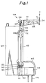
- Fig. 1 is a perspective view of a printer in which a piezoelectric printing head is used.
- the printer includes a piezoelectric printing head 21, a platen 22, and a guide 23.
- the piezoelectric printing head 21 is mounted on a carrier which is movable along the platen 22 and guided by the guide 23. The head 21 is moved together with the carrier so as to conduct printing.
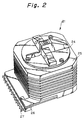
- Fig. 2 is a perspective view of the piezoelectric printing head 21 of Fig. 1.
- the printing head 21 has a nose 24, to guide printing wires for conducting the printing operation, a heat sink 25, a printed circuit board 26, and a connector 27.
- Fig. 3 is a side view of the general structure of the piezoelectric printing head 21.
- a piezoelectric actuator assembly 128 is provided in the heat sink 25 of the piezoelectric printing head 21.
- Fig. 4 is a side view of a piezoelectric actuator assembly 128 embodying the present invention and including a base frame 129, a piezoelectric element 130, and an armature 131 of a magnifying mechanism 132.
- An end block 133 is secured to a lower end portion of the piezoelectric element 130 and is connected with the frame 129 (the specific connection structure will be described later).
- a plurality of piezoelectric elements 130 are circumferentially disposed at predetermined intervals around the printing head, and a magnifying mechanism 132 with an armature 131 is provided for each piezoelectric element 130.
- the armature 131 comprises a beam 135, a tip portion of which carries a printing wire 134, the beam 135 being integrally secured at its other end to a base portion 136.
- the magnifying mechanism 132 includes a support spring 137 and a movable spring 138 that are arranged to be approximately parallel to one another. The two ends of the support spring 137 are connected with the base portion 136 and the frame 129 respectively, and the two ends of the movable spring 138 are connected respectively with the base portion 136 and a block 139 (different from the frame 129).
- a piezoelectric actuator assembly 1208 the end block 133 is secured to the frame 129 as shown in Fig. 5.
- the securing system is constituted in the following manner: a screw-threaded member (an adjustment screw) 140, the tip of which has a protruding portion 141, is screwed into the frame 129 so as to be opposed to the end block 133.
- a recess 142 is provided in the end block 133, and the protruding portion 141 of the screw 140 is engaged in the recess 142.
- the adjustment screw 140 is fastened to the end block 133 by means of an adhesive agent 143 located in the recess 142, between the protruding portion 141 and the block 133.
- the screw 140 is adjusted so that the piezoelectric element 130 is subjected thereby to a pre-stressing force directed upwardly along the element condition.
- a voltage is applied to the piezoelectric element 130 through a connector 144.
- the upper end of the piezoelectric element 130 is displaced upward, so that the movable spring 138 is pushed up.
- the armature 131 is thereby caused to rotate in the direction of an arrow shown in Fig. 4 by the action of the magnifying mechanism 132.
- a magnified displacement is thus transmitted to the wire 134.
- the wire 134 is moved in the direction of arrow C by a predetermined amount. In this manner, the printing is carried out.
- the piezoelectric element 130 and the armature 131 return to their respective initial dispositions.
- the end block 133 is connected with the frame 129 in such a manner that a pre-stressing force, in the direction from the end block 133 to the armature 131, is applied to the piezoelectric element 130, compressive deformation of the previously applied adhesive agent, which caused magnification losses in prior printing heads, is less likely to occur. This facilitates high speed printing operations.
- the adhesive agent 143 strengthens the engagement between the end block 133 and the protruding portion 141, as compared with piezoelectric printing heads not using such adhesive.
- a terminal 144a of a connector 144 is connected with the common connector 27 (Fig. 3) through the printed board 26 (Fig. 3).
- the terminal 144a is connected with each electrode of the piezoelectric element 130 through a lead wire 145. In this way, electrical power is supplied to the piezoelectric element 130 through the connector 27.
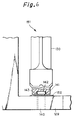
- Fig. 6 is a side view of parts of a second embodiment of the present invention, in which anti-adhesion means 152 made of polytetrafluoroethylene or silicon are added to the piezoelectric actuator assembly 128 shown in Figs. 4 and 5.
- a region of the frame base 129 that is opposed to the lower end of the element 130 is coated with the anti-adhesion means 152 so as to prevent adhesion of the adhesive material 143 onto the surface of the frame base 129.
- the adhesive material 143 spills downward from the gap between the protruding portion 141 of the screw threaded member 140 and the recess 142, it does not adhere to the base 129 since it is prevented from doing so by this anti-adhesion means 152.
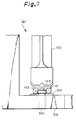
- Fig. 7 is a side view of parts of a third embodiment of the present invention, in which a sheet-like anti-adhesion member 162 made of polytetrafluoroethylene or silicon is added to the piezoelectric actuator assembly 128 shown in Figs. 4 and 5.
- the member 162 is located on the frame base 129 at a location below the lower end of the element 130, as shown in the drawing, so that surplus adhesive agent is prevented from adhering to the frame base 129.
Landscapes
- Impact Printers (AREA)
Description
- The present invention relates to printing heads employing piezoelectric actuation elements.
- Electromagnetic-type printing heads are generally unsuitable for use in high speed impact dot-matrix printers. Therefore, printing heads using piezoelectric actuators have been considered. However, the amount of displacement caused directly by the expansion and contraction of a piezoelectric element is generally very small, of the order of only several microns, and so needs to be magnified by a magnifying mechanism in order that printing operations can be carried out.
- A conventional piezoelectric printing head, for example that shown in US 4,874,978, includes a common base frame, a piezoelectric element, an armature, and a magnifying mechanism. A plurality of piezoelectric elements are circumferentially provided in predetermined positions, and an armature and a magnifying mechanism are provided for each piezoelectric element. The piezoelectric element has an end block which is secured to the base frame by means of adhesive.
- The armature has a beam, and a printing wire is secured to a tip of the beam. The magnifying mechanism includes a support spring and a movable spring that are arranged in parallel with one another. Upper end portions of the springs are secured to the armature. A lower end portion of the support spring is secured to the base frame, and a lower end portion of the movable spring is secured to the piezoelectric element. The piezoelectric printing head is mounted on a carrier, and moved on a platen together with the carrier. Printing is conducted when a predetermined piezoelectric element is driven at a predetermined time in the process of moving.
- Application of a voltage to a piezoelectric element causes the upper end of the piezoelectric element to be displaced upward. The magnifying mechanism is activated and the armature is rotated, so that the wire is forced to conduct a printing motion. When the printing has been completed, the supply of voltage impressed upon the piezoelectric element is removed and the armature returns to its initial position together with the piezoelectric element.
- In such a printing head, when the movable spring is pushed up by displacement of the piezoelectric element, an adhesive agent which connects the piezoelectric element with the base frame may be deformed by a reaction force. Accordingly, a magnification ratio or characteristic frequency of the magnifying mechanism may be lowered, thereby causing a magnifying loss which can prevent high speed printing being carried out satisfactorily.
- According to the present invention, there is provided a printing head comprising a plurality of actuators mounted on a frame, each actuator comprising a piezoelectric actuation element secured at a first end region thereof to the frame and at a second end region thereof to an end region of an armature carrying a printing element, wherein activation of the said actuation element causes the said end region of the armature to be displaced through a first distance in a direction from the said first end region of the actuation element to the said second end region thereof, thereby causing the printing element to be displaced through a second distance in that direction, which second distance is larger than the said first distance,
characterised in that the said first end region of the actuation element is secured to the frame by means of a screw-threaded member, one end of which is attached to the said first end region by means of adhesive material interposed between the screw-threaded member and the said first end region, the screw-threaded member being adjusted to apply a pre-stressing force to the said actuation element in the direction from the said first end region to the said second end region. - Preferably, the said one end of the screw-threaded member is engaged in a recess formed in a block secured to the said first end region of the actuation element, the said adhesive material being located, in the said recess, between the said one end and the said block.
- Alternatively, a protruding part of a block secured to the said first end region of the actuation element may be engaged in a recess formed in the said one end of the screw-threaded member the said adhesive material being located, in the said recess, between the said one end and the said block.
- Anti-adhesion means may be provided, on the said frame over at least a region thereof that is opposed to the said first end region of the actuation element, for preventing the said adhesive material from becoming attached to the said frame.
- Such anti-adhesion means may comprise a film or sheet of polytetrafluoroethylene or silicon.
- The pre-stressing force applied in an embodiment of the present invention can serve to reduce the aforementioned problems caused by deformation of adhesive between the piezoelectric element and the frame.
- For a better understanding of the invention and to show how the same may be carried into effect, reference will now be made, by way of example, to the accompanying drawings, wherein:
- Fig. 1 is a perspective view of a printer in which a piezoelectric printing head embodying the present invention can be used;
- Fig. 2 is a perspective view of a piezoelectric printing head embodying the present invention;
- Fig. 3 is a sectioned side view of the general structure of the piezoelectric printing head of Fig. 2;
- Fig. 4 is a side view of a piezoelectric actuator assembly embodying the present invention;
- Fig. 5 is an enlarged side view of parts of the assembly of Fig. 4;
- Fig. 6 is a side view of parts of a second piezoelectric actuator assembly embodying the present invention; and
- Fig. 7 is a side view of parts of a third piezoelectric actuator assembly embodying the present invention.
- Fig. 1 is a perspective view of a printer in which a piezoelectric printing head is used. The printer includes a
piezoelectric printing head 21, aplaten 22, and aguide 23. Thepiezoelectric printing head 21 is mounted on a carrier which is movable along theplaten 22 and guided by theguide 23. Thehead 21 is moved together with the carrier so as to conduct printing. - Fig. 2 is a perspective view of the
piezoelectric printing head 21 of Fig. 1. Theprinting head 21 has anose 24, to guide printing wires for conducting the printing operation, aheat sink 25, a printedcircuit board 26, and aconnector 27. - Fig. 3 is a side view of the general structure of the
piezoelectric printing head 21. Apiezoelectric actuator assembly 128 is provided in theheat sink 25 of thepiezoelectric printing head 21. - Fig. 4 is a side view of a
piezoelectric actuator assembly 128 embodying the present invention and including abase frame 129, apiezoelectric element 130, and anarmature 131 of amagnifying mechanism 132. - An
end block 133 is secured to a lower end portion of thepiezoelectric element 130 and is connected with the frame 129 (the specific connection structure will be described later). A plurality ofpiezoelectric elements 130 are circumferentially disposed at predetermined intervals around the printing head, and amagnifying mechanism 132 with anarmature 131 is provided for eachpiezoelectric element 130. - The
armature 131 comprises abeam 135, a tip portion of which carries aprinting wire 134, thebeam 135 being integrally secured at its other end to abase portion 136. Themagnifying mechanism 132 includes asupport spring 137 and amovable spring 138 that are arranged to be approximately parallel to one another. The two ends of thesupport spring 137 are connected with thebase portion 136 and theframe 129 respectively, and the two ends of themovable spring 138 are connected respectively with thebase portion 136 and a block 139 (different from the frame 129). - In such a
piezoelectric actuator assembly 128, theend block 133 is secured to theframe 129 as shown in Fig. 5. The securing system is constituted in the following manner: a screw-threaded member (an adjustment screw) 140, the tip of which has aprotruding portion 141, is screwed into theframe 129 so as to be opposed to theend block 133. Arecess 142 is provided in theend block 133, and theprotruding portion 141 of thescrew 140 is engaged in therecess 142. Theadjustment screw 140 is fastened to theend block 133 by means of anadhesive agent 143 located in therecess 142, between theprotruding portion 141 and theblock 133. Thescrew 140 is adjusted so that thepiezoelectric element 130 is subjected thereby to a pre-stressing force directed upwardly along the element condition. - In a printing operation, a voltage is applied to the
piezoelectric element 130 through aconnector 144. As a result, the upper end of thepiezoelectric element 130 is displaced upward, so that themovable spring 138 is pushed up. Thearmature 131 is thereby caused to rotate in the direction of an arrow shown in Fig. 4 by the action of themagnifying mechanism 132. A magnified displacement is thus transmitted to thewire 134. As a result, thewire 134 is moved in the direction of arrow C by a predetermined amount. In this manner, the printing is carried out. After the printing operation has been completed, thepiezoelectric element 130 and thearmature 131 return to their respective initial dispositions. - Since, in the embodiment of the present invention described above, the
end block 133 is connected with theframe 129 in such a manner that a pre-stressing force, in the direction from theend block 133 to thearmature 131, is applied to thepiezoelectric element 130, compressive deformation of the previously applied adhesive agent, which caused magnification losses in prior printing heads, is less likely to occur. This facilitates high speed printing operations. Theadhesive agent 143 strengthens the engagement between theend block 133 and the protrudingportion 141, as compared with piezoelectric printing heads not using such adhesive. - A
terminal 144a of aconnector 144 is connected with the common connector 27 (Fig. 3) through the printed board 26 (Fig. 3). Theterminal 144a is connected with each electrode of thepiezoelectric element 130 through alead wire 145. In this way, electrical power is supplied to thepiezoelectric element 130 through theconnector 27. - Fig. 6 is a side view of parts of a second embodiment of the present invention, in which anti-adhesion means 152 made of polytetrafluoroethylene or silicon are added to the
piezoelectric actuator assembly 128 shown in Figs. 4 and 5. A region of theframe base 129 that is opposed to the lower end of theelement 130 is coated with the anti-adhesion means 152 so as to prevent adhesion of theadhesive material 143 onto the surface of theframe base 129. - In the embodiment, if the
adhesive material 143 spills downward from the gap between the protrudingportion 141 of the screw threadedmember 140 and therecess 142, it does not adhere to the base 129 since it is prevented from doing so by this anti-adhesion means 152. - Fig. 7 is a side view of parts of a third embodiment of the present invention, in which a sheet-
like anti-adhesion member 162 made of polytetrafluoroethylene or silicon is added to thepiezoelectric actuator assembly 128 shown in Figs. 4 and 5. Themember 162 is located on theframe base 129 at a location below the lower end of theelement 130, as shown in the drawing, so that surplus adhesive agent is prevented from adhering to theframe base 129.
Claims (5)
- A printing head comprising a plurality of actuators (128) mounted on a frame (129), each actuator comprising a piezoelectric actuation element (130) secured at a first end region thereof to the frame and at a second end region thereof to an end region of an armature (131) carrying a printing element (134), wherein activation of the said actuation element causes the said end region of the armature to be displaced through a first distance in a direction from the said first end region of the actuation element (130) to the said second end region thereof, thereby causing the printing element (134) to be displaced through a second distance in that direction, which second distance is larger than the said first distance,
characterised in that the said first end region of the actuation element (130) is secured to the frame (129) by means of a screw-threaded member (140), one end of which is attached to the said first end region by means of adhesive material (143) interposed between the screw-threaded member (140) and the said first end region, the screw-threaded member (140) being adjusted to apply a pre-stressing force to the said actuation element (130) in the direction from the said first end region to the said second end region. - A printing head as claimed in claim 1, wherein the said one end of the screw-threaded member (140) is engaged in a recess formed in a block (133) secured to the said first end region of the actuation element, the said adhesive material being located, in the said recess, between the said one end and the said block.
- A printing head as claimed in claim 1, wherein a protruding part of a block (133) secured to the said first end region of the actuation element (130) is engaged in a recess formed in the said one end of the screw-threaded member (140), the said adhesive material being located, in the said recess, between the said one end and the said block.
- A printing head as claimed in claim 1, 2 or 3, wherein anti-adhesion means (152, 162) are provided, on the said frame (129) over at least a region thereof that is opposed to the said first end region of the actuation element (130), for preventing the said adhesive material (143) from becoming attached to the said frame (129).
- A printing head as claimed in claim 4, wherein the said anti-adhesion means comprise a film or sheet (152, 162) of polytetrafluoroethylene or silicon.
Priority Applications (1)
| Application Number | Priority Date | Filing Date | Title |
|---|---|---|---|
| EP96117009A EP0756938A3 (en) | 1992-05-08 | 1993-05-07 | Printing head |
Applications Claiming Priority (6)
| Application Number | Priority Date | Filing Date | Title |
|---|---|---|---|
| JP116064/92 | 1992-05-08 | ||
| JP4116064A JP2797231B2 (en) | 1992-05-08 | 1992-05-08 | Piezo print head |
| JP116065/92 | 1992-05-08 | ||
| JP4116065A JP2797232B2 (en) | 1992-05-08 | 1992-05-08 | Piezoelectric print head and method of manufacturing piezoelectric print head |
| JP16447092A JPH06975A (en) | 1992-06-23 | 1992-06-23 | Printing head |
| JP164470/92 | 1992-06-23 |
Related Child Applications (2)
| Application Number | Title | Priority Date | Filing Date |
|---|---|---|---|
| EP96117009A Division EP0756938A3 (en) | 1992-05-08 | 1993-05-07 | Printing head |
| EP96117009.9 Division-Into | 1996-10-23 |
Publications (3)
| Publication Number | Publication Date |
|---|---|
| EP0569253A2 EP0569253A2 (en) | 1993-11-10 |
| EP0569253A3 EP0569253A3 (en) | 1994-08-24 |
| EP0569253B1 true EP0569253B1 (en) | 1997-08-13 |
Family
ID=27313077
Family Applications (2)
| Application Number | Title | Priority Date | Filing Date |
|---|---|---|---|
| EP93303560A Expired - Lifetime EP0569253B1 (en) | 1992-05-08 | 1993-05-07 | Printing head |
| EP96117009A Ceased EP0756938A3 (en) | 1992-05-08 | 1993-05-07 | Printing head |
Family Applications After (1)
| Application Number | Title | Priority Date | Filing Date |
|---|---|---|---|
| EP96117009A Ceased EP0756938A3 (en) | 1992-05-08 | 1993-05-07 | Printing head |
Country Status (3)
| Country | Link |
|---|---|
| US (1) | US5447381A (en) |
| EP (2) | EP0569253B1 (en) |
| DE (1) | DE69313004T2 (en) |
Families Citing this family (2)
| Publication number | Priority date | Publication date | Assignee | Title |
|---|---|---|---|---|
| JP2806414B2 (en) * | 1992-08-18 | 1998-09-30 | 富士通株式会社 | Electromechanical transducer and printhead |
| US5907211A (en) * | 1997-02-28 | 1999-05-25 | Massachusetts Institute Of Technology | High-efficiency, large stroke electromechanical actuator |
Family Cites Families (19)
| Publication number | Priority date | Publication date | Assignee | Title |
|---|---|---|---|---|
| US3927410A (en) * | 1974-04-30 | 1975-12-16 | Ibm | Ink jet nozzle |
| DE2710935A1 (en) * | 1977-03-12 | 1978-09-14 | Ibm Deutschland | MATRIX PRINTER WITH PIEZOELECTRICALLY DRIVEN PRINT NEEDLES |
| JPS5981181A (en) * | 1982-11-01 | 1984-05-10 | Nec Corp | Printing head for electrostrictive-type wire dot printer |
| JPS59150756A (en) * | 1983-02-17 | 1984-08-29 | Nec Corp | Printing mechanism |
| JPS6048372A (en) * | 1983-08-26 | 1985-03-16 | Hitachi Ltd | Printing head |
| JPS60208256A (en) * | 1984-04-02 | 1985-10-19 | Hitachi Ltd | print head |
| JPS61195857A (en) * | 1985-02-25 | 1986-08-30 | Tadashi Sekiguchi | Printer |
| JPS63130175A (en) * | 1986-11-13 | 1988-06-02 | エヌ・シー・アール・インターナショナル・インコーポレイテッド | Moving piezoelectric element actuator-unit |
| US4874978A (en) * | 1987-06-09 | 1989-10-17 | Brother Kogyo Kabushiki Kaisha | Device for magnifying displacement of piezoelectric element or the like and method of producing same |
| JP2555608B2 (en) * | 1987-06-10 | 1996-11-20 | ブラザー工業株式会社 | Displacement conversion device for piezoelectric element |
| CA1319295C (en) * | 1988-03-18 | 1993-06-22 | Akio Yano | Printing head of wire-dot impact printer |
| SE469665B (en) * | 1989-07-11 | 1993-08-16 | Forsheda Ab | Vibration dampers cause damping of vibrations in one surface |
| JP2864554B2 (en) * | 1989-09-05 | 1999-03-03 | ブラザー工業株式会社 | Method of assembling piezoelectric element in motion conversion device for piezoelectric element |
| US5167458A (en) * | 1989-11-01 | 1992-12-01 | Oki Electric Industry Co., Ltd. | Wire driving mechanism |
| JPH03231866A (en) * | 1990-02-07 | 1991-10-15 | Brother Ind Ltd | Dot print head |
| US5133612A (en) * | 1990-10-03 | 1992-07-28 | Brother Kogyo Kabushiki Kaisha | Dot impact type printing head with adhesively attached base unit |
| JPH04282261A (en) * | 1991-03-08 | 1992-10-07 | Brother Ind Ltd | Print gap detection device in print head |
| JP2668460B2 (en) * | 1991-05-23 | 1997-10-27 | 富士通株式会社 | Piezo element print head |
| JP2965763B2 (en) * | 1991-10-09 | 1999-10-18 | 富士通株式会社 | Holding structure of piezoelectric actuator |
-
1993
- 1993-05-07 DE DE69313004T patent/DE69313004T2/en not_active Expired - Fee Related
- 1993-05-07 EP EP93303560A patent/EP0569253B1/en not_active Expired - Lifetime
- 1993-05-07 EP EP96117009A patent/EP0756938A3/en not_active Ceased
-
1995
- 1995-01-17 US US08/373,452 patent/US5447381A/en not_active Expired - Fee Related
Also Published As
| Publication number | Publication date |
|---|---|
| US5447381A (en) | 1995-09-05 |
| DE69313004D1 (en) | 1997-09-18 |
| EP0569253A2 (en) | 1993-11-10 |
| DE69313004T2 (en) | 1997-12-04 |
| EP0756938A3 (en) | 1998-01-14 |
| EP0569253A3 (en) | 1994-08-24 |
| EP0756938A2 (en) | 1997-02-05 |
Similar Documents
| Publication | Publication Date | Title |
|---|---|---|
| US5113204A (en) | Ink jet head | |
| EP0295102B1 (en) | Device for magnifying displacement of piezoelectric element or the like | |
| JPH078571B2 (en) | Springs for interconnection of conductor areas | |
| KR0121752B1 (en) | Motion transducer of piezoelectric element and manufacturing method thereof | |
| US5485192A (en) | Thermal printhead | |
| KR102870823B1 (en) | Piezo actuator and piezo actuator array | |
| EP0350258B1 (en) | Dot matrix printing heads | |
| US5245356A (en) | Thermal printing head | |
| US6404453B1 (en) | Thermal printhead and clip pin used for the same | |
| EP0477642A2 (en) | Thermal head for a thermal printer | |
| US5447381A (en) | Piezoelectric printing head | |
| JP3242886B2 (en) | Thermal head, method of manufacturing thermal head, and printer | |
| JP2905602B2 (en) | Scan head support plate | |
| JPH0631946A (en) | Mounting structure of connecting wire to printed wiring board | |
| JPS63144054A (en) | Printing head | |
| EP0616894B1 (en) | Printing head device | |
| CA2236609A1 (en) | Thermal head and its fabrication method | |
| JPH05309848A (en) | Piezoelectric print head | |
| JPH0699596A (en) | Device for connecting conductors to drive means for print head | |
| JP2867405B2 (en) | Inkjet head | |
| JP2000062190A (en) | Method and device for ejecting ink to base body and manufacture thereof | |
| JP2004142464A (en) | Interconnected system | |
| JP2797231B2 (en) | Piezo print head | |
| JP3019662B2 (en) | Current recording head and method of manufacturing the same | |
| JPH0637470A (en) | Fitting structure of printed wiring board to circuit board |
Legal Events
| Date | Code | Title | Description |
|---|---|---|---|
| PUAI | Public reference made under article 153(3) epc to a published international application that has entered the european phase |
Free format text: ORIGINAL CODE: 0009012 |
|
| AK | Designated contracting states |
Kind code of ref document: A2 Designated state(s): DE GB |
|
| 17P | Request for examination filed |
Effective date: 19940503 |
|
| PUAL | Search report despatched |
Free format text: ORIGINAL CODE: 0009013 |
|
| AK | Designated contracting states |
Kind code of ref document: A3 Designated state(s): DE GB |
|
| 17Q | First examination report despatched |
Effective date: 19951206 |
|
| GRAG | Despatch of communication of intention to grant |
Free format text: ORIGINAL CODE: EPIDOS AGRA |
|
| GRAH | Despatch of communication of intention to grant a patent |
Free format text: ORIGINAL CODE: EPIDOS IGRA |
|
| GRAH | Despatch of communication of intention to grant a patent |
Free format text: ORIGINAL CODE: EPIDOS IGRA |
|
| GRAA | (expected) grant |
Free format text: ORIGINAL CODE: 0009210 |
|
| AK | Designated contracting states |
Kind code of ref document: B1 Designated state(s): DE GB |
|
| DX | Miscellaneous (deleted) | ||
| REF | Corresponds to: |
Ref document number: 69313004 Country of ref document: DE Date of ref document: 19970918 |
|
| PLBE | No opposition filed within time limit |
Free format text: ORIGINAL CODE: 0009261 |
|
| STAA | Information on the status of an ep patent application or granted ep patent |
Free format text: STATUS: NO OPPOSITION FILED WITHIN TIME LIMIT |
|
| 26N | No opposition filed | ||
| REG | Reference to a national code |
Ref country code: GB Ref legal event code: IF02 |
|
| PGFP | Annual fee paid to national office [announced via postgrant information from national office to epo] |
Ref country code: GB Payment date: 20030507 Year of fee payment: 11 |
|
| PGFP | Annual fee paid to national office [announced via postgrant information from national office to epo] |
Ref country code: DE Payment date: 20030515 Year of fee payment: 11 |
|
| PG25 | Lapsed in a contracting state [announced via postgrant information from national office to epo] |
Ref country code: GB Free format text: LAPSE BECAUSE OF NON-PAYMENT OF DUE FEES Effective date: 20040507 |
|
| PG25 | Lapsed in a contracting state [announced via postgrant information from national office to epo] |
Ref country code: DE Free format text: LAPSE BECAUSE OF NON-PAYMENT OF DUE FEES Effective date: 20041201 |
|
| GBPC | Gb: european patent ceased through non-payment of renewal fee |
Effective date: 20040507 |