EP0568929B1 - Optical low pass filter - Google Patents
Optical low pass filter Download PDFInfo
- Publication number
- EP0568929B1 EP0568929B1 EP93107030A EP93107030A EP0568929B1 EP 0568929 B1 EP0568929 B1 EP 0568929B1 EP 93107030 A EP93107030 A EP 93107030A EP 93107030 A EP93107030 A EP 93107030A EP 0568929 B1 EP0568929 B1 EP 0568929B1
- Authority
- EP
- European Patent Office
- Prior art keywords
- wavelength
- low pass
- materials
- filter
- optical
- Prior art date
- Legal status (The legal status is an assumption and is not a legal conclusion. Google has not performed a legal analysis and makes no representation as to the accuracy of the status listed.)
- Expired - Lifetime
Links
Images


Classifications
-
- G—PHYSICS
- G02—OPTICS
- G02B—OPTICAL ELEMENTS, SYSTEMS OR APPARATUS
- G02B5/00—Optical elements other than lenses
- G02B5/18—Diffraction gratings
- G02B5/1866—Transmission gratings characterised by their structure, e.g. step profile, contours of substrate or grooves, pitch variations, materials
- G02B5/1871—Transmissive phase gratings
-
- G—PHYSICS
- G02—OPTICS
- G02B—OPTICAL ELEMENTS, SYSTEMS OR APPARATUS
- G02B27/00—Optical systems or apparatus not provided for by any of the groups G02B1/00 - G02B26/00, G02B30/00
- G02B27/42—Diffraction optics, i.e. systems including a diffractive element being designed for providing a diffractive effect
- G02B27/46—Systems using spatial filters
-
- H—ELECTRICITY
- H04—ELECTRIC COMMUNICATION TECHNIQUE
- H04N—PICTORIAL COMMUNICATION, e.g. TELEVISION
- H04N23/00—Cameras or camera modules comprising electronic image sensors; Control thereof
- H04N23/50—Constructional details
- H04N23/55—Optical parts specially adapted for electronic image sensors; Mounting thereof
Definitions
- the present invention generally relates to an optical low pass filter including a phase grating for obtaining useful picture image characteristics by provision of preferable low pass effects for each wavelength region about the spatial frequency components beyond the Nyquist limit which are required to be removed as the picture images are discretely sampled in nature in an optical system of a single tube color television camera having a color separating filter, a color video camera using solid state imaging elements, and so on.
- the present invention relates to an optical low pass filter which is easier to fabricate.
- the spatial frequency components of the Nyquist limit or more should be removed before images are inputted into the solid imaging elements, because the images of the photographed objects image-formed on the imaging elements include the components beyond the Nyquist limit of the spatial sampling of the solid imaging elements.
- the picture image signal components beyond the Nyquist limit display the construction not provided originally with respect to the output picture images or become Moire stripes, spurious colors and so on. Therefore, conventionally the higher spatial frequency components in the photographed object to be inputted to the solid state imaging elements are restricted by the disposition of optical low pass filters in one portion of the imaginating system.
- optical low pass filters including phase gratings have been adapted to be used for this purpose.
- an optical low pass filter comprising a plurality of prismatic elongated elements made of at least two different transparent materials and arranged alternately side by side in an array so as to form a planar plate whose thickness is equal to the height of the cross section of each of the prismatic elements and such that the materials constituting any two contiguous elements are different, contiguous prismatic elements being bounded together along their confronting faces by means of a bounding agent, such that no additional supporting plate for the prismatic elements is necessary and the thickness of the filter device can be reduced.
- an optical system which includes an optical low pass filter comprising a plurality of prismatic elongated elements made of at least two different transparent materials and arranged alternately side by side in an array perpendicular with respect to an optical axis in the optical system so as to form a planar plate whose thickness is equal to the height of the cross section of each of the prismatic elements and such that the materials constituting any two contiguous elements are different, contiguous prismatic elements being bounded together along their confronting faces by means of a bounding agent, such that no additional supporting plate for the prismatic elements is necessary and the thickness of the filter device can be reduced.
- an optical low pass filter comprising a plurality of prismatic elongated elements made of at least two different transparent materials and arranged alternately side by side in an array perpendicular with respect to an optical axis in the optical system so as to form a planar plate whose thickness is equal to the height of the cross section of each of the prismatic elements and such that the materials constituting any two contiguous elements are different, contig
- the construction can be made thinner with the thickness being restricted only to the phase difference generating portion.
- an easier coping operation can be effected even with respect to optical line pass adjustment or mechanical adjustment.
- the optical low pass filer needs to show superior MTF (Modulation Transfer Function) characteristics at the same time. Also, in order to meet the demands of the larger camera market, a method capable of mass production is required.
- two materials are arranged side by side in a flat shape, these two materials being equal in refractive index at a certain wavelength in a useable wavelength region and different in refractive index dispersion.
- the optical low pass effect of the wavelength selectivity can be obtained by the phase difference caused by the refractive index of the two different materials having a wavelength dependence in the projection from the phase grating.
- the forming operation can be effected in the thickness of the phase difference generating portion only, so that the present phase grating can be constructed thinner. In the actual insertion thereof into the imaging system, a more compact lens system can be constructed.
- the present invention provides an optical low pass filter comprising at least two types of different optical material members, each having a shape of prism, which are aligned in contact with each other in the direction of the height of prisms being parallel so as to form a single sheet.
- the filter becomes thin so as to provide a portion for generating a phase difference, and is superior for mass-production as compared to filters formed of a phase lattice on a base plate by means of pressing, cutting and holographic grating.
- the filter of the present invention at least two types of different optical material members are alternately provided in contact with each other in parallel prism shapes to generate a refractive index difference between the two adjacent optical materials and a phase difference according to the shape of prism to obtain an effect of a phase lattice.
- the phase lattice obtained from the filter of the present invention is designed only by a portion for generating a phase difference without providing a base plate for holding a phase difference to make the construction very thin only with the portion of phase difference.
- the present invention provides a thin filter which can reduce the design problems, and can form a compact optical system.
- a filter of the minimum thickness can be constructed for an optical low pass filter of the phase lattice type having a property of waveselection.
- the phase lattice filter is constructed by forming prisms with two types of materials combined with materials of different refractive index dispersion and equal refractive index in a certain wavelength and aligning the prisms in contact with each other so as to form a single plate, a large low pass effect can be obtained for a phase difference to the great extent in response to the large value of refractive index difference to be disposed between adjacent materials having shapes of prisms for generating the phase difference.
- the smaller the refractive index difference between adjacent materials is, the smaller the phase difference is, and the low pass effect obtained by the diffraction becomes small.
- the low pass effect by the diffraction becomes smaller.
- the refractive index difference of two materials become larger and the low pass effect by the diffraction become larger.
- the optical low pass effect becomes weaker near the reference wavelength ⁇ , thus resulting in the MTF characteristics retained higher so far as the region of the high spatial frequency components.
- the optical low pass effect functions large in the wavelength region away from the reference wavelength ⁇ , thus resulting in attenuated MTF characteristics in the comparatively low spatial frequency region.
- the phase grating optical low pass filter itself can be constructed in thickness of the phase difference generation portion only in the present construction, the construction can be made thinner. It can be used without the new construction of the special optical system even in the case of the insertion on the way to the lens system.
- the cut-off spatial frequency in the wavelength region of the green component of the primary color filter is adapted to become higher, the cut-off frequency in the red or the blue wavelength region is adapted to become lower in accordance with the present invention, an imaging system of higher brilliance resolution degree and less color Moire can be constructed, because the green contributes most towards the brilliance signal.
- Fig. 1(a) and 1(b) show a principle construction example of the present invention.
- a first constructing member 1 of prism shape i.e., an oblique prism and a second constructing member 2 of prism shape made of a material different from that of the first member 1 are fixed together at the adjacent boundary faces 3 thereof filled with a bonding agent or resin 4.
- the members of prisms 1 and 2 are aligned on a sheet of plate in contact with each other to form a plane plate.
- a position where an optical low pass filter including a phase grating is desired to be a position where a multiple varying operation is completed in the zoom lens or the like, with an effect that the present invention can be obtained by the arrangement of a phase grating like reference numeral 9.
- the optical low pass filter including a selectivity phase grating can be moved by the varying multiplication with the zoom, the position is not necessarily restricted to the position of Fig. 2. The equivalent performance can be obtained if the position is provided between the photographed object 5 and the lens system 6 or in the lens system 6.
- Fig. 3 shows one example of a combination of materials for realizing the low pass effect about only the blue and red components without having the low pass effect about the green component.
- the first member 1 in Fig. 1(a) and (b) is made of an optical glass having refractive index nd of 1.56907 and Abbe's number ⁇ d of 71.3
- the second member is made of an optical glass having refractive index nd of 1.56732 and Abbe's number ⁇ d of 42.8, the respective refractive index curves of materials 1 and 2 being shown by 10 and 11, wherein the lateral axis is wavelength, while the longitudinal axis is refractive index.
- the members 1 and 2 of different materials have a crossing point whereat the refractive index becomes equal between the waveform ranges of 470 nm to 600 nm of green color, and the refractive index difference becomes larger as moved apart from the wavelength picture having the refractive index being equal.
- the refractive index of optical materials is normally a value listed on a catalogue, and, since it is possible to change the refractive index of materials according to the property of the filter in practical use, it says that it is possible to provide a wavelength, at which the refractive index becomes equal, in the whole range of wavelength of green color.
- Fig. 4 shows a cross section of an optical low pass filter of phase lattice being possible for selecting the wavelength, which is constructed in accordance with the following conditions so that the cut-off frequency becomes 47.5 line pair / mm with the refractive index of materials to be used for splicing being 1.56.
- the bonding agent is used with a UV resin which is hardened by projecting ultraviolet radiation.
- MTF The property of MTF is calculated in algebra on the basis of shape of the materials, and the relationship among the pitch of lattice, interval of filter image planes and wavelength are provided on the consideration of the refractive index being different on the wavelength and the shut-out frequency to be required.
- ⁇ is a pitch of lattice, ⁇ a phase difference, n1 (a) and n2 (a) a refractive index, ⁇ a wavelength, and h a height of phase portion.
- ⁇ 2 ⁇ ( n 1 ( ⁇ )- n 2 ( ⁇ )) h ⁇
- Fig. 5 shows the construction which is adapted to take in the picture image signals of a video camera composed of optical low pass filters using wavelength selectivity phase gratings in an embodiment shown in Fig. 4.
- the inputting signals from the imaging elements 15 are outputted in picture image through the steps of a sample hold 16, an automatic gain control 17, a ⁇ correction 18, a signal processing 19 and so on.
- the respective processing steps can be constructed even in a different order.
- a low pass filter of having a low pass effect combined with the Nyquist frequency of the sampling of the green region must be added.
- the phase grating is adapted not to cause effects in a vertical direction in the video camera system shown in Fig. 5, the low pass filter about the vertical direction is also required to be added.
- the low pass filter to be added may become a crystal filter or a phase grating filter.
- the optical low pass filter including a wavelength selectivity phase grating and the optical low pass filter for obtaining the low pass effect in the green region are not always required to be joined.
- the phase grating filter of the wavelength selectivity may be in order provided in either the object side or the image face side.
- the resolution in the vertical direction can be raised by the use of the optical low pass filter including the phase grating of the present invention with respect to the vertical direction, and can be constructed to have the effect with respect to the two-dimensional direction.
- a video camera optical system having effects in both the horizontal direction and vertical direction can be constructed by the insertion of one wavelength selectivity phase grating optical low pass filter through the proper rotation of the phase grating filter of the present invention with respect to the optical axis direction.
Landscapes
- Physics & Mathematics (AREA)
- General Physics & Mathematics (AREA)
- Optics & Photonics (AREA)
- Engineering & Computer Science (AREA)
- Multimedia (AREA)
- Signal Processing (AREA)
- Color Television Image Signal Generators (AREA)
Description

Claims (8)
- An optical low pass filter, comprising a plurality of prismatic elongated elements (1, 2) made of at least two different transparent materials and arranged alternately side by side in an array so as to form a planar plate (9) whose thickness is equal to the height of the cross section of each of the prismatic elements and such that the materials constituting any two contiguous elements are different, contiguous prismatic elements (1, 2) being bounded together along their confronting faces (3) by means of a bonding agent (4), such that no additional supporting plate for the prismatic elements (1, 2) is necessary and the thickness of the filter device can be reduced.
- An optical system which includes an optical low pass filter according to claim 1, the plate of said low pass filter being arranged perpendicularly with respect to an optical axis in the optical system.
- The filter as defined in claim 1 or the system as defined in claim 2, wherein the adjacent two prismatic elements (1, 2) are made of different materials, respectively, which are selected as optical materials having equal refractive indexes but different refractive index dispersions at a certain wavelength of usable wavelength range so as to obtain the optical low pass effect.
- The filter or the system as defined in claim 3, wherein the following conditions are satisfied,(1) when the refractive indexes of the two different materials for a given wavelength λ are respectively n1(λ) and n2(λ), at a wavelength λ in the range of 470 nm < λ < 600 nm, the refractive indexes of the two materials satisfy the following formula,(2) when the Abbe's numbers of the two materials are respectively v d1 and v d2, the Abbe's numbers of the two materials satisfy the following inequality:
- The filter as defined in claim 1 or the system as defined in claim 2, wherein said contiguous prismatic elements (1, 2) are joined together by a resin.
- The system as defined in claims 2 and 3 further including a primary color filter, and wherein the optical low pass filter has a trapezoidal cross section and the following conditions are satisfied,
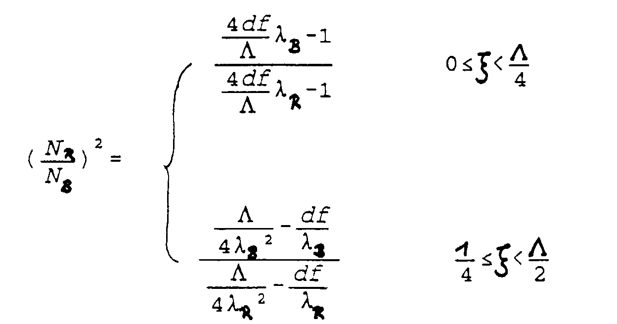
- The system as defined in claim 6, wherein NR and NB are calculated by the following formulas:
- The system as defined in claim 6 or 7, wherein a video camera is composed using the optical low pass filter.
Applications Claiming Priority (2)
| Application Number | Priority Date | Filing Date | Title |
|---|---|---|---|
| JP4113438A JPH05313098A (en) | 1992-05-06 | 1992-05-06 | Optical low pass filter |
| JP113438/92 | 1992-05-06 |
Publications (2)
| Publication Number | Publication Date |
|---|---|
| EP0568929A1 EP0568929A1 (en) | 1993-11-10 |
| EP0568929B1 true EP0568929B1 (en) | 1998-03-18 |
Family
ID=14612232
Family Applications (1)
| Application Number | Title | Priority Date | Filing Date |
|---|---|---|---|
| EP93107030A Expired - Lifetime EP0568929B1 (en) | 1992-05-06 | 1993-04-30 | Optical low pass filter |
Country Status (4)
| Country | Link |
|---|---|
| US (1) | US5375013A (en) |
| EP (1) | EP0568929B1 (en) |
| JP (1) | JPH05313098A (en) |
| DE (1) | DE69317464T2 (en) |
Family Cites Families (5)
| Publication number | Priority date | Publication date | Assignee | Title |
|---|---|---|---|---|
| JPS56147120A (en) * | 1980-04-18 | 1981-11-14 | Victor Co Of Japan Ltd | Optical low-pass filter |
| JPS57180313U (en) * | 1981-05-13 | 1982-11-16 | ||
| JPS61149923A (en) * | 1984-12-25 | 1986-07-08 | Sony Corp | Optical low-pass filter of phase type |
| US5237446A (en) * | 1987-04-30 | 1993-08-17 | Olympus Optical Co., Ltd. | Optical low-pass filter |
| JP2800364B2 (en) * | 1990-04-27 | 1998-09-21 | 松下電器産業株式会社 | Optical low-pass filter |
-
1992
- 1992-05-06 JP JP4113438A patent/JPH05313098A/en active Pending
-
1993
- 1993-04-30 DE DE69317464T patent/DE69317464T2/en not_active Expired - Fee Related
- 1993-04-30 US US08/054,134 patent/US5375013A/en not_active Expired - Lifetime
- 1993-04-30 EP EP93107030A patent/EP0568929B1/en not_active Expired - Lifetime
Also Published As
| Publication number | Publication date |
|---|---|
| US5375013A (en) | 1994-12-20 |
| EP0568929A1 (en) | 1993-11-10 |
| JPH05313098A (en) | 1993-11-26 |
| DE69317464D1 (en) | 1998-04-23 |
| DE69317464T2 (en) | 1998-10-15 |
Similar Documents
| Publication | Publication Date | Title |
|---|---|---|
| EP0952474B1 (en) | Projection lens and focus adjusting method for projection lens | |
| US5280388A (en) | Wavelength selective phase grating optical low-pass filter | |
| JP2861525B2 (en) | Wavelength-selective phase grating optical low-pass filter | |
| US7583442B2 (en) | Extended depth of field optical systems | |
| US5995279A (en) | Optical element, and taking optical system and image pickup apparatus using it | |
| US5237446A (en) | Optical low-pass filter | |
| US20030057353A1 (en) | Wavefront coding zoom lens imaging systems | |
| EP1067779A2 (en) | Image pickup apparatus | |
| EP1067802A2 (en) | Colour image pickup apparatus | |
| CA2120099C (en) | Image pickup optical system which minimizes the effects of spurious signals | |
| EP0584769A2 (en) | Two-dimensional optical low-pass filter | |
| US6980248B1 (en) | Image pickup apparatus | |
| US6273568B1 (en) | Projection apparatus | |
| US6507437B1 (en) | Diffractive optical element and photographic optical system having the same | |
| US5434709A (en) | Wavelength-selective phase grating type optical low-pass filter comprising adhesive layer between transparent layers | |
| US20020163725A1 (en) | Diffracting optical element, and optical system and optical apparatus having the same | |
| US5321251A (en) | Angled optical fiber filter for reducing artifacts in imaging apparatus | |
| US4444472A (en) | Lens system having color separation optics | |
| JP3397758B2 (en) | Imaging device | |
| US4058827A (en) | Color separating optical system for a television camera | |
| US6538825B1 (en) | Zoom lens | |
| US4682237A (en) | Photographic optical apparatus | |
| US5375013A (en) | Optical low pass filter | |
| US20010010594A1 (en) | Optical low-pass filter | |
| US7256947B2 (en) | Optical element having minute periodic structure |
Legal Events
| Date | Code | Title | Description |
|---|---|---|---|
| PUAI | Public reference made under article 153(3) epc to a published international application that has entered the european phase |
Free format text: ORIGINAL CODE: 0009012 |
|
| 17P | Request for examination filed |
Effective date: 19930430 |
|
| AK | Designated contracting states |
Kind code of ref document: A1 Designated state(s): DE FR GB NL |
|
| 17Q | First examination report despatched |
Effective date: 19950925 |
|
| GRAG | Despatch of communication of intention to grant |
Free format text: ORIGINAL CODE: EPIDOS AGRA |
|
| GRAG | Despatch of communication of intention to grant |
Free format text: ORIGINAL CODE: EPIDOS AGRA |
|
| GRAH | Despatch of communication of intention to grant a patent |
Free format text: ORIGINAL CODE: EPIDOS IGRA |
|
| GRAH | Despatch of communication of intention to grant a patent |
Free format text: ORIGINAL CODE: EPIDOS IGRA |
|
| GRAA | (expected) grant |
Free format text: ORIGINAL CODE: 0009210 |
|
| RAP1 | Party data changed (applicant data changed or rights of an application transferred) |
Owner name: MATSUSHITA ELECTRIC INDUSTRIAL CO., LTD. |
|
| AK | Designated contracting states |
Kind code of ref document: B1 Designated state(s): DE FR GB NL |
|
| REF | Corresponds to: |
Ref document number: 69317464 Country of ref document: DE Date of ref document: 19980423 |
|
| ET | Fr: translation filed | ||
| PLBE | No opposition filed within time limit |
Free format text: ORIGINAL CODE: 0009261 |
|
| 26N | No opposition filed | ||
| REG | Reference to a national code |
Ref country code: GB Ref legal event code: IF02 |
|
| PGFP | Annual fee paid to national office [announced via postgrant information from national office to epo] |
Ref country code: GB Payment date: 20040428 Year of fee payment: 12 |
|
| PGFP | Annual fee paid to national office [announced via postgrant information from national office to epo] |
Ref country code: DE Payment date: 20040513 Year of fee payment: 12 |
|
| PGFP | Annual fee paid to national office [announced via postgrant information from national office to epo] |
Ref country code: FR Payment date: 20050408 Year of fee payment: 13 |
|
| PG25 | Lapsed in a contracting state [announced via postgrant information from national office to epo] |
Ref country code: GB Free format text: LAPSE BECAUSE OF NON-PAYMENT OF DUE FEES Effective date: 20050430 |
|
| PG25 | Lapsed in a contracting state [announced via postgrant information from national office to epo] |
Ref country code: DE Free format text: LAPSE BECAUSE OF NON-PAYMENT OF DUE FEES Effective date: 20051101 |
|
| GBPC | Gb: european patent ceased through non-payment of renewal fee |
Effective date: 20050430 |
|
| PGFP | Annual fee paid to national office [announced via postgrant information from national office to epo] |
Ref country code: NL Payment date: 20060417 Year of fee payment: 14 |
|
| REG | Reference to a national code |
Ref country code: FR Ref legal event code: ST Effective date: 20061230 |
|
| NLV4 | Nl: lapsed or anulled due to non-payment of the annual fee |
Effective date: 20071101 |
|
| PG25 | Lapsed in a contracting state [announced via postgrant information from national office to epo] |
Ref country code: NL Free format text: LAPSE BECAUSE OF NON-PAYMENT OF DUE FEES Effective date: 20071101 |
|
| PG25 | Lapsed in a contracting state [announced via postgrant information from national office to epo] |
Ref country code: FR Free format text: LAPSE BECAUSE OF NON-PAYMENT OF DUE FEES Effective date: 20060502 |