EP0568602B1 - Method of monitoring the position of a sensor - Google Patents
Method of monitoring the position of a sensor Download PDFInfo
- Publication number
- EP0568602B1 EP0568602B1 EP92904139A EP92904139A EP0568602B1 EP 0568602 B1 EP0568602 B1 EP 0568602B1 EP 92904139 A EP92904139 A EP 92904139A EP 92904139 A EP92904139 A EP 92904139A EP 0568602 B1 EP0568602 B1 EP 0568602B1
- Authority
- EP
- European Patent Office
- Prior art keywords
- sensor
- coil circuit
- magnetic field
- coil
- calibration
- Prior art date
- Legal status (The legal status is an assumption and is not a legal conclusion. Google has not performed a legal analysis and makes no representation as to the accuracy of the status listed.)
- Expired - Lifetime
Links
- 238000000034 method Methods 0.000 title claims abstract description 24
- 238000012544 monitoring process Methods 0.000 title claims description 10
- 230000008859 change Effects 0.000 claims abstract description 30
- 230000006698 induction Effects 0.000 claims abstract description 12
- 238000001514 detection method Methods 0.000 claims abstract description 9
- 230000010363 phase shift Effects 0.000 claims abstract description 9
- 239000012530 fluid Substances 0.000 claims description 17
- 239000011888 foil Substances 0.000 claims description 16
- 239000012528 membrane Substances 0.000 claims description 13
- 239000000853 adhesive Substances 0.000 claims description 4
- 230000001070 adhesive effect Effects 0.000 claims description 4
- 239000004020 conductor Substances 0.000 claims description 4
- 239000000463 material Substances 0.000 claims description 4
- 229910052782 aluminium Inorganic materials 0.000 abstract description 10
- XAGFODPZIPBFFR-UHFFFAOYSA-N aluminium Chemical compound [Al] XAGFODPZIPBFFR-UHFFFAOYSA-N 0.000 abstract description 10
- 238000010438 heat treatment Methods 0.000 description 8
- BQCADISMDOOEFD-UHFFFAOYSA-N Silver Chemical compound [Ag] BQCADISMDOOEFD-UHFFFAOYSA-N 0.000 description 7
- 229910052709 silver Inorganic materials 0.000 description 7
- 239000004332 silver Substances 0.000 description 7
- 238000005259 measurement Methods 0.000 description 6
- 239000011521 glass Substances 0.000 description 5
- 239000011505 plaster Substances 0.000 description 5
- 239000003792 electrolyte Substances 0.000 description 4
- 230000007423 decrease Effects 0.000 description 3
- 230000001419 dependent effect Effects 0.000 description 3
- 229910052751 metal Inorganic materials 0.000 description 3
- 239000002184 metal Substances 0.000 description 3
- 239000007787 solid Substances 0.000 description 3
- 230000004913 activation Effects 0.000 description 2
- 238000013459 approach Methods 0.000 description 2
- 238000010586 diagram Methods 0.000 description 2
- 238000006073 displacement reaction Methods 0.000 description 2
- 230000000694 effects Effects 0.000 description 2
- 238000001727 in vivo Methods 0.000 description 2
- 238000012623 in vivo measurement Methods 0.000 description 2
- 229920001296 polysiloxane Polymers 0.000 description 2
- BVKZGUZCCUSVTD-UHFFFAOYSA-M Bicarbonate Chemical compound OC([O-])=O BVKZGUZCCUSVTD-UHFFFAOYSA-M 0.000 description 1
- 241001465754 Metazoa Species 0.000 description 1
- 238000004026 adhesive bonding Methods 0.000 description 1
- 238000004082 amperometric method Methods 0.000 description 1
- 230000008901 benefit Effects 0.000 description 1
- 239000008280 blood Substances 0.000 description 1
- 210000004369 blood Anatomy 0.000 description 1
- 239000000919 ceramic Substances 0.000 description 1
- 230000008878 coupling Effects 0.000 description 1
- 238000010168 coupling process Methods 0.000 description 1
- 238000005859 coupling reaction Methods 0.000 description 1
- 238000001035 drying Methods 0.000 description 1
- 230000003993 interaction Effects 0.000 description 1
- 150000002500 ions Chemical class 0.000 description 1
- 239000000203 mixture Substances 0.000 description 1
- 230000003287 optical effect Effects 0.000 description 1
- 238000003969 polarography Methods 0.000 description 1
- 238000004313 potentiometry Methods 0.000 description 1
- 238000012545 processing Methods 0.000 description 1
- 230000002787 reinforcement Effects 0.000 description 1
- 239000000523 sample Substances 0.000 description 1
- 238000005070 sampling Methods 0.000 description 1
- 230000007704 transition Effects 0.000 description 1
Images



Classifications
-
- A—HUMAN NECESSITIES
- A61—MEDICAL OR VETERINARY SCIENCE; HYGIENE
- A61B—DIAGNOSIS; SURGERY; IDENTIFICATION
- A61B5/00—Measuring for diagnostic purposes; Identification of persons
- A61B5/145—Measuring characteristics of blood in vivo, e.g. gas concentration or pH-value ; Measuring characteristics of body fluids or tissues, e.g. interstitial fluid or cerebral tissue
- A61B5/1468—Measuring characteristics of blood in vivo, e.g. gas concentration or pH-value ; Measuring characteristics of body fluids or tissues, e.g. interstitial fluid or cerebral tissue using chemical or electrochemical methods, e.g. by polarographic means
- A61B5/1477—Measuring characteristics of blood in vivo, e.g. gas concentration or pH-value ; Measuring characteristics of body fluids or tissues, e.g. interstitial fluid or cerebral tissue using chemical or electrochemical methods, e.g. by polarographic means non-invasive
-
- A—HUMAN NECESSITIES
- A61—MEDICAL OR VETERINARY SCIENCE; HYGIENE
- A61B—DIAGNOSIS; SURGERY; IDENTIFICATION
- A61B5/00—Measuring for diagnostic purposes; Identification of persons
- A61B5/06—Devices, other than using radiation, for detecting or locating foreign bodies ; Determining position of diagnostic devices within or on the body of the patient
- A61B5/061—Determining position of a probe within the body employing means separate from the probe, e.g. sensing internal probe position employing impedance electrodes on the surface of the body
- A61B5/062—Determining position of a probe within the body employing means separate from the probe, e.g. sensing internal probe position employing impedance electrodes on the surface of the body using magnetic field
-
- A—HUMAN NECESSITIES
- A61—MEDICAL OR VETERINARY SCIENCE; HYGIENE
- A61B—DIAGNOSIS; SURGERY; IDENTIFICATION
- A61B5/00—Measuring for diagnostic purposes; Identification of persons
- A61B5/145—Measuring characteristics of blood in vivo, e.g. gas concentration or pH-value ; Measuring characteristics of body fluids or tissues, e.g. interstitial fluid or cerebral tissue
- A61B5/14539—Measuring characteristics of blood in vivo, e.g. gas concentration or pH-value ; Measuring characteristics of body fluids or tissues, e.g. interstitial fluid or cerebral tissue for measuring pH
-
- A—HUMAN NECESSITIES
- A61—MEDICAL OR VETERINARY SCIENCE; HYGIENE
- A61B—DIAGNOSIS; SURGERY; IDENTIFICATION
- A61B5/00—Measuring for diagnostic purposes; Identification of persons
- A61B5/145—Measuring characteristics of blood in vivo, e.g. gas concentration or pH-value ; Measuring characteristics of body fluids or tissues, e.g. interstitial fluid or cerebral tissue
- A61B5/14542—Measuring characteristics of blood in vivo, e.g. gas concentration or pH-value ; Measuring characteristics of body fluids or tissues, e.g. interstitial fluid or cerebral tissue for measuring blood gases
-
- A—HUMAN NECESSITIES
- A61—MEDICAL OR VETERINARY SCIENCE; HYGIENE
- A61B—DIAGNOSIS; SURGERY; IDENTIFICATION
- A61B5/00—Measuring for diagnostic purposes; Identification of persons
- A61B5/145—Measuring characteristics of blood in vivo, e.g. gas concentration or pH-value ; Measuring characteristics of body fluids or tissues, e.g. interstitial fluid or cerebral tissue
- A61B5/1491—Heated applicators
Definitions
- the present invention relates to a method of monitoring the position of a sensor.
- the invention also relates to a system for monitoring the position of a sensor.
- Sensors for measuring the presence of one or several components in a fluid have been known for several decades.
- the components may be for example ions or in the form of gas and be present in various fluids.
- the sensors may be based on various measuring principles, for example electrochemical measuring principles such as potentiometry, amperometry and polarography, and optical measuring principles.
- the determination of the position may be to detect whether the sensor is located correctly in a measuring chamber, as for example in measuring devices wherein a replaceable sensor is located in a combined measuring and calibration chamber built into a monitor.
- the determination may also simply comprise detection of where in the system the sensor is, as for example in measuring devices for in vivo measurements where the sensor during measuring is in direct contact with a patient and during calibration is located in a separate calibration chamber. To ensure that the sensor is not calibrated when located on a patient, it may be necessary automatically to check whether the sensor is present in the calibration chamber when calibration is activated.
- An example of such measuring device is the monitor of the type TCM3 from Radiometer A/S, Copenhagen, Denmark. Said monitor is adapted for transcutaneous (tc) measuring of the O2 and/or CO2 content in blood. Calibration of a sensor in the form of an electrode connected to the monitor is performed with the electrode located in a calibration chamber placed in the monitor itself to which the calibration gas is supplied through a tube assembly from a separate calibration device.
- a micro switch is built into the calibration chamber, detecting whether the electrode is located in the chamber.
- activation of the calibration is only possible when the micro switch detects that the electrode is in position in the chamber.
- the information from the micro switch may be used to control several other functions in the monitor as well.
- the heat supply to the electrode is shut off after 30 minutes in the chamber, ensuring that the electrolyte between the electrode and the membrane does not evaporate disproportionately quickly when the electrode is not used.
- other functions - necessary only when measuring - are disconnected, for example the acoustic alarm is suppressed and the curve printout and the data sampling by a connected recorder are stopped.
- the TCM3 monitor itself is a compact portable unit, but the relating calibration device, which has a volume corresponding to half the volume of the monitor (24 x 8 x 23 cm), makes the entire unit quite unwieldy.
- the calibration device is a mass-produced disposable device and comprises primarily a base foil into which a completely closed calibration cup is pressed, containing the fluid for calibration of a sensor.
- a sensor When a sensor is to be calibrated, it is inserted into the calibration device whereby the cover of the calibration cup is ruptured, the sensor penetrates into the cup and is brought in contact with the calibration fluid.
- the advantage is obtained that when calibrating the electrode mentioned above need not be placed in a calibration chamber on the monitor, but calibration can be performed in close proximity to the patient.
- the electrode need not be removed from the incubator during calibration, as the calibration device is so small that it can easily be placed inside the incubator.
- the calibration device does not render it possible to use the micro switch mentioned in connection with the TCM3 monitor to detect whether the electrode is present in the calibration chamber, as no electronic parts exist in the separate calibration device.
- To build a micro switch into the electrode is not a good solution to the problem; firstly it will make the electrode large and unwieldy and secondly the risk of the micro switch being activated by other than the calibration device is too big.
- the gel required in order to establish a good contact between the electrode and the skin of a patient is likely to contaminate the micro switch, causing failures and faulty detections.
- the object of the invention is to provide a method for a safe monitoring of the position of a sensor.
- a sensor for measuring a component of a fluid comprising a coil integrated in a coil circuit, wherein a magnetic field is generated, the coil is constructed and arranged in the sensor in such a way that the magnetic field produced in the coil circuit extends beyond the delimitations of the sensor, the magnetic field in the coil circuit is intermittently detected, the mutual induction between the coil circuit and the surroundings of the sensor is detected as a change of the magnetic field in the coil circuit, a first predefined position of the sensor is defined by the sensor being in mechanical engagement with first engagement means of a chamber adapted for the sensor, said first engagement means comprising a material for varying the magnetic field in the coil circuit when the sensor is in the first position, and on the basis of the intermittent detection of the magnetic field in the coil circuit, it is monitored when the sensor is in the first predefined position, or when in another position in which the sensor it is not in engagement with
- the magnetic field in the coil circuit of the sensor may be generated by applying an alternating voltage across the coil circuit or making an alternating current flow through the circuit.
- the extension of the magnetic field depends on the magnitude of the applied voltage or current.
- a counteracting magnetic field will be produced in that object, the magnitude of which i.a. is dependent on the distance between the sensor and the object.
- the resulting developed mutual induction between the coil circuit and the object outside the sensor will change the magnetic field in the coil circuit.
- the magnetic field in the coil circuit changes, the alternating voltage across and the alternating current through the coil circuit as well as the phase of each of these change.
- US Patent No. US 4,526,177 discloses a sensor or probe used for locating metallic objects misplaced in a human or animal body, such as bullets, broken scalpel blades, surgical needles, etc.
- the sensor comprises a coil. When the sensor is not near a metallic object, the voltage drop across the coil remains constant. When the sensor approaches a metallic object, the voltage will drop.
- the sensor disclosed in the specification of US Patent No. US 4,526,177 is not a sensor for measuring a component of a fluid as the sensor according to the present invention. Moreover, the prior art sensor is not mechanically engaged with engagement means and no detection of its position takes place.
- the method comprises that for a given measurement parameter, the signal ranges, which represent given positions of the sensor, are predetermined. At a given time, the position of the sensor is then determined by comparing the signal for the magnetic field in the coil circuit detected at said given time with the predetermined signal ranges.
- the quantity and the sign of the difference between signal values relating to given positions of the sensor are predetermined for a given measurement parameter.
- a change of position of the sensor between two given positions is then detected by the occurrence of a change in the detected signal for the magnetic field in the coil circuit, said change being larger than or equal to the predetermined quantity and having the related sign.
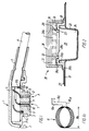
- the embodiment shown in Fig. 1 of an electrode to be used by the method according to the invention comprises a combined electrode 1 for transcutaneous (tc) measuring of pCO2 and pO2.
- the electrode is constructed primarily in the same manner as existing well-known tc electrodes, for example the combined tc electrode of the type E5280 from Radiometer A/S, Copenhagen, Denmark.
- the electrode 1 comprises an electrode housing 2 into which an electrode body 3 of silver is glued.
- the electrode housing 2 is closed by a protection cap 4.
- the electrode 1 is by means of a cable 6 connected to a monitor (not shown), which controls the functions relating to in vivo monitoring, i.a. switch on/switch off of current circuits, processing of data, etc.
- the transition between the electrode 1 and the cable 6 is strengthened by a flexible bush 5.
- the sensor parts 7 and 8 for measuring of pCO2 and pO2 are located in the electrode body 3.
- the sensor parts 7 and 8 are located in such a manner that their measuring surfaces end on the outwards extending surface of the silver body 3.
- Measuring of pCO2 is based on measuring of pH.
- the pCO2 sensor part 7 comprises a solid state element 9 and a conductive wire 10, which connects the solid state element 9 with the cable 6.
- the solid state element 9 is constructed of several layers.
- the outer layer is a pH sensitive glass layer arranged on a layer of conductive glass which again is arranged on an intermediate conductor of Pt. All of this is carried by an insulating, ceramic basis.
- the conductive glass layer converts the measurement signal from the pH sensitive glass into electric signals and transmits said signals through the intermediate conductor to the conductive wire 10, which is surrounded by an insulating plastic tube 11 at the center of the silver body 3.
- the pO2 sensor part 8 comprises a Pt wire 12 embedded in a glass element 13.
- the Pt wire 12 is connected with the cable 6 in the electrode housing 2.
- the electrode body 3 further comprises a heating element 14 in the form of a zener diode for heating of the electrode and the skin on which measurement is to be performed and a heat sensor (not shown) in the form of an NTC resistor.
- the heating element 14 as well as the heat sensor are by means of the cable 6 connected with the controlling monitor.
- the silver body 3 of the electrode 1 also serves as a reference electrode and for that purpose it is chlorinated on its surface facing the electrode front.
- the silver body 3 is also by means of the cable 6 connected with the monitor.
- the electrode housing 2 further comprises a coil 15, located in an annular groove along the outer edges of the interior of the electrode housing 2.
- the coil 15 is at its ends 15a and 15b connected to the cable 6. The function of the coil 15 will be explained further in connection with Figs. 7, 8 and 9.
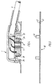
- FIG. 2 A sectional view of a calibration device 20 adapted to the electrode 1 is shown in Fig. 2, primarily comprising a calibration chamber, a membraning device, and a fixation means.
- the calibration device 20 consists of a silicone-coated base foil 21 into which is pressed and glued a foil cup 22 of aluminum, the edge of which ends in an outwards extending flange 22a.
- a cover 23, of aluminum foil too, is welded onto the flange 22a and closes the cup 22 tightly so that no exchange of matter will take place between a fluid contained in the chamber 24 delimited by said parts and the surroundings.
- the chamber 24 serves as a calibration chamber and contains a calibration fluid 25 with a well-known composition suitable for calibration of the electrode 1, the content of O2 and CO2 differing from the content of these components in the air.
- the calibration fluid may consist of for example 15% O2, 5% CO2 and the remainder N2.
- the cup 22 is at its upper part, which is not attached to the base foil 21, surrounded by a fixation ring 26 consisting of a smooth tube section with two circular flanges located at each end of the tube section, the upper flange 26a of which extends inwardly and the lower flange 26b extends outwards.
- a fixation plaster 27 consisting of a gel adhesive with a mesh reinforcement is attached to the lower flange 26b of the fixation ring 26.
- the fixation plaster 27 is adapted to hold the fixation ring 26 against a not necessarily plane surface, for example the base foil 21, human skin, etc.
- a squeezing ring 28 consisting of an annular ring 28a with upwards extending tabs 28b located along the outside edge which are elastically displaceable in radial direction, is located over the cover 23 within the flange 26a, so that the ring 28a engages with the flange 26a.
- a 15 ⁇ m PP membrane 29 of the type which is usually used in tc electrodes for measuring of pO2 and pCO2 is located.
- the calibration device 20 is closed by a protection cap 30. At the bottom of the spacing 31, which is delimited by the fixation ring 26 and the protection cap 30, is located an bicarbonate-containing electrolyte.
- any used membrane, etc. must be removed so that the electrode looks like the one shown in Fig. 1.
- the protection cap 30 on the calibration device 20 is removed and the electrode 1 is inserted into the calibration device 20 while attempting to center the silver body 3 of the electrode 1 in relation to the squeezing ring 28 in the calibration device 20.
- the electrode front will press against the aluminum cover 23, which at a time will be ruptured and bend into the calibration chamber 24.
- some of the electrolyte fluid from the chamber 31 will flow into the chamber 24 and wet the calibration fluid contained herein.
- the remainder of the electrolyte fluid is locked up between the electrode body 3 and the membrane 29.
- the projecting parts 16 of the electrode housing 2 will abut on the surface 32 of the circular ring 28a, and the squeezing ring 28 will be pressed downwardly in relation to the fixation ring 26.
- the tabs 28b will be pressed inwardly against the part of the electrode housing 2 surrounding the electrode body 3.
- the top surface 34 of the flange 26a of the fixation ring 26 abuts on the downward surface 17 of the electrode housing 2, a projecting part 2a of the electrode housing 2 is fixedly engaged with a projecting part 26c of the fixation ring 26, and the squeezing ring 28 is wedged between the fixation ring 26 and the electrode 1.
- the membrane 29 is stretched across the electrode front and held between the squeezing ring 28 and the fixation ring 26.
- the two parts, the electrode 1 and the calibration device 20, are now locked together and the electrode 1 is ready for calibration.
- the electrode 1 may, if desired, remain in the calibration chamber 24 after calibration, whereby the risk of the electrode 1 drying out is reduced while kept at ready mode.
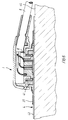
- Fig. 4 shows a sectional view of the calibrated and membranated electrode 1 with a mounted fixation means after the electrode 1 is released from the calibration chamber 24.
- the electrode front with the measuring electrodes 7 and 8 may now be applied a dose of contact gel and then placed at the desired measuring site on the patient.
- the fastening to the skin of a patient is carried out by means of the fixation plaster 27 only.
- the electrode 1 may be kept (parked) in a special parking means 40 shown in Fig. 5.
- the parking means 40 consists of a metal ring 41, for example of aluminum, fixedly mounted on one side of a piece of silicone-treated plastic foil 42.
- the side of the foil 42 opposite the ring 41 is adhesive and on delivery protected by another, easily removable piece of foil 43.
- the ring 41 is adapted to the annular groove 33, which is delimited by the elements located at the electrode 1, the fixation ring 26, and the squeezing ring 28.
- the parking means 40 may be placed where desired.
- Fig. 6 shows the electrode 1 parked in a parking means 40 which after removal of the protection foil 43 is located on a surface 44, for example on a wall in an incubator.
- the used membrane 29, the squeezing ring 28, and the fixation ring 26 are removed by stripping off the fixation ring 26 from its engagement with the electrode housing 2 whereafter the membrane 29, the squeezing ring 28 and the fixation ring 26 are discarded.
- the electrode 1 is now ready for recalibration.
- the electrode 1 Before using the electrode 1 shown on the drawing, including calibration and measuring, the electrode 1 is by means of the cable 6 connected to a monitor (not shown) which i.a. is a control unit for all the functions relating to calibration and measuring.
- the monitor controls for example thermostating of the electrode 1 by means of the heating element 14 and the heat sensor, collection and printout of measurement data as well as some control functions, which activate the alarm function when measurement or control values are beyond the specified ranges.
- These functions are all known from former monitors for existing tc electrodes, for example the monitor mentioned above of the type TCM3 from Radiometer A/S, Copenhagen, Denmark.
- This monitor comprises a micro switch built into the calibration chamber which detects whether the electrode is positioned in the chamber.
- a similar function is obtained by the electrode 1 according to the invention by using the coil 15 mentioned in connection with Fig. 1.
- a sinusoidal alternating voltage U with a peak value U peak 1 V and a frequency f u 150 KHz is applied to the coil circuit.
- the circuit diagram in Fig. 7, comprising two circuits 50 and 54 shows the above-mentioned system.
- the upper circuit 50 corresponds to the coil circuit in the electrode 1 with a coil 51 corresponding to the coil 15.
- the lower circuit 54 represents the aluminum cup 22, which acts as a short-circuit.
- the distance d1 between the two circuits is variable, corresponding to the distance between the electrode 1 and the calibration device 22 being variable.
- Fig. 8 is shown how the peak value U s,peak of the voltage across the coil circuit varies with the distance d between the surface 17 of the electrode housing 2 and the surface 34 of the upper flange 26a of the fixation ring 26.
- U peak 1 V
- frequency f u 150 kH.
- the steepness of the curve on the first part results in that the electrode 1 need not to be lifted very much from the calibration device 20 before the measured voltage U s,peak shows an unmistakably detectable change. As also seen from the drawing, it will also be unmistakably detectable whether the electrode 1 is lifted completely out of the calibration device 20, for example when the electrode 1 is to be used for measuring on a patient. There will, of course, be some uncertainty in the values U s,min. and U s,max. , i.a. dependent on the tolerance of the coil 15 and of the accuracy of gluing of the silver body 3.
- a first embodiment according to the invention comprises to detect in which position the electrode 1 is located. This is done by currently detecting the magnetic field in the coil circuit and comparing the detected signal with the predetermined signals for the positions of the electrode 1 - in this case U s,min. (the electrode 1 in position for calibration) and U s,max. (the electrode 1 in position for measuring). As a result of the uncertainty mentioned above in these values, detected values within a certain range around U s,min. and U s,max. , respectively will be accepted as representing these values.
- the detected voltage U s,peak will lie within the range around U s,max. . Now the electrode 1 is thermostated by means of the heating element 14, alarm functions, etc. are connected, and calibration can no longer be activated. With the voltage U s,peak in this range, the electrode 1 is adjusted for in vivo measurement.
- Fig. 9 is shown how the phase shift ⁇ f u of the voltage U s across the coil circuit varies with the distance d.
- the ring 41 will - in a similar manner to the cup 22 - influence the coil circuit so that the detected change in the voltage U s,peak or the phase shift ⁇ f u no longer lies within the ranges around U s,max. or ⁇ f u,min. (cf. Fig. 8).
- the ring 41 can be constructed in such a manner that it provides an equal detected signal for the voltage U s,peak or the phase shift ⁇ f u as that of the cup 22.
- the functions mentioned in connection with calibration are connected/disconnected, said functions relating to a position where the electrode 1 is not applied for measuring.
- the ring 41 on the parking means 40 may be constructed in such a manner that its influence on the coil circuit result in the detected signal for the voltage U s,peak or the phase shift ⁇ f u will fall within a third range separated from the two others.
- the functions mentioned previously may also on this signal be connected/disconnected, but then it will not be possible to activate a calibration.
- Metal objects other than the calibration cup 22 and the parking means ring 41 are also able to influence the coil circuit and cause a changed signal for the voltage U s,peak or the phase shift ⁇ f u .
- the coil 15 is, however, constructed and located in such a manner that only objects which penetrate into the groove 33 formed by the fixation ring 26 and the squeezing ring 28 (cf. Fig. 4) can cause a displacement of the detected signal for the magnetic field, corresponding to the electrode 1 being located in the calibration device 20 (U s,min. , ⁇ f u,max. ). For example, if the electrode 1 is placed on a metal surface, the detected signal will only be displaced to a value between the signal corresponding to an open-air position (U s,max.
- the electrode 1 In another embodiment it is not detected in which position the electrode 1 is located, but it is detected whether the electrode 1 changes its position. This is done by detecting the magnetic field in the coil circuit as mentioned above by measuring one of said parameters. When calibration is activated, a certain signal is detected. The monitor will not be adjusted for measuring on a patient until it detects that the measured signal changes more than a certain predetermined value and in a certain direction. The quantity and direction of this limit value is determined on the basis of the premeasured signals, when the electrode 1 is in measuring position (on a patient) and when the electrode 1 is in calibration position (in the calibration device 20), respectively. To safeguard against that a considerable unintended effect on the coil circuit is detected as a change of position, an alarm function will be activated if the detected change is considerably larger than the limit value.
- the limit value is determined on the basis of U s,max. and U s,min. .
- the monitor will in this case not be adjusted for measuring on a patient until it detects that the signal for the peak value U s,peak of the voltage across the coil circuit detected at calibration is increased by approx. 35 mV.
- the monitor will, when it detects a decrease in the detected signal of approx. 35 mV, interpret this as if the electrode 1 has been transferred to a calibration device 20, and the functions mentioned previously in connection with calibration will be connected/disconnected.
- the sought limit value for the change is determined on the basis of ⁇ f u,min. and ⁇ f u,max. .
- the monitor is not adjusted for measuring until the detected signal for ⁇ f u decreases by approx. 2.1°.
- the parking means 40 mentioned previously may, of course, be used by this method also. If the ring 41 on the parking means 40 is constructed in such a manner that it provides the same effect on the coil circuit of the electrode 1 as that of the calibration cup 22, the alarm functions, etc. mentioned previously will be connected/disconnected when removing the electrode 1 from a patient to the parking means.
- the ring 41 may, however, be constructed in such a manner that its influence on the coil circuit is different from that of the calibration cup 22. For example, if the signal from the influence of the ring 41 on the coil circuit is between the signals from the calibration cup 22 and the open air, then only the corresponding further limit values for the changes and the related directions need be entered to the monitor.
- the coil 15 has the only function to form part of the circuit producing the magnetic field, with which the surroundings of the electrode 1 (the calibration cup 22, the ring 41) interact.
- the coil may, however, in another embodiment have more functions.
- the coil may also act as a heating element for the electrode whereby the heating element mentioned in connection with Fig. 1 may be excluded.
- the invention may, of course, be used for monitoring of the positions of any types of sensors for measuring a fluid component.
- a coil must be built into the sensor which is able to interact with the surroundings in the different positions in the manner as mentioned above.
Landscapes
- Health & Medical Sciences (AREA)
- Life Sciences & Earth Sciences (AREA)
- Physics & Mathematics (AREA)
- Engineering & Computer Science (AREA)
- Medical Informatics (AREA)
- Public Health (AREA)
- Veterinary Medicine (AREA)
- Biophysics (AREA)
- Pathology (AREA)
- General Health & Medical Sciences (AREA)
- Biomedical Technology (AREA)
- Heart & Thoracic Surgery (AREA)
- Animal Behavior & Ethology (AREA)
- Molecular Biology (AREA)
- Surgery (AREA)
- Optics & Photonics (AREA)
- Chemical & Material Sciences (AREA)
- Chemical Kinetics & Catalysis (AREA)
- General Chemical & Material Sciences (AREA)
- Human Computer Interaction (AREA)
- Geophysics And Detection Of Objects (AREA)
- Measuring And Recording Apparatus For Diagnosis (AREA)
- Measurement Of Length, Angles, Or The Like Using Electric Or Magnetic Means (AREA)
- Measurement And Recording Of Electrical Phenomena And Electrical Characteristics Of The Living Body (AREA)
Abstract
Description
- The present invention relates to a method of monitoring the position of a sensor. The invention also relates to a system for monitoring the position of a sensor.
- Sensors for measuring the presence of one or several components in a fluid have been known for several decades. The components may be for example ions or in the form of gas and be present in various fluids. The sensors may be based on various measuring principles, for example electrochemical measuring principles such as potentiometry, amperometry and polarography, and optical measuring principles.
- It is common to most of the sensors that at a time during use they must be located in a certain position, and it may be of crucial importance that the sensor is located correctly. To ensure this, many systems are provided with position detectors. The determination of the position may be to detect whether the sensor is located correctly in a measuring chamber, as for example in measuring devices wherein a replaceable sensor is located in a combined measuring and calibration chamber built into a monitor. The determination may also simply comprise detection of where in the system the sensor is, as for example in measuring devices for in vivo measurements where the sensor during measuring is in direct contact with a patient and during calibration is located in a separate calibration chamber. To ensure that the sensor is not calibrated when located on a patient, it may be necessary automatically to check whether the sensor is present in the calibration chamber when calibration is activated.
- An example of such measuring device is the monitor of the type TCM3 from Radiometer A/S, Copenhagen, Denmark. Said monitor is adapted for transcutaneous (tc) measuring of the O₂ and/or CO₂ content in blood. Calibration of a sensor in the form of an electrode connected to the monitor is performed with the electrode located in a calibration chamber placed in the monitor itself to which the calibration gas is supplied through a tube assembly from a separate calibration device.
- To ensure that calibration of the electrode is not performed while the electrode is located on a patient, a micro switch is built into the calibration chamber, detecting whether the electrode is located in the chamber. Thus, activation of the calibration is only possible when the micro switch detects that the electrode is in position in the chamber.
- Apart from controlling the possibility of calibration, the information from the micro switch may be used to control several other functions in the monitor as well. With the electrode located in the calibration chamber, the heat supply to the electrode is shut off after 30 minutes in the chamber, ensuring that the electrolyte between the electrode and the membrane does not evaporate disproportionately quickly when the electrode is not used. Moreover, other functions - necessary only when measuring - are disconnected, for example the acoustic alarm is suppressed and the curve printout and the data sampling by a connected recorder are stopped.
- The TCM3 monitor itself is a compact portable unit, but the relating calibration device, which has a volume corresponding to half the volume of the monitor (24 x 8 x 23 cm), makes the entire unit quite unwieldy.
- In order to provide a measuring system which is easy to carry, a new type of calibration device has been developed with much smaller dimensions (approx. 4 x 1 x 4 cm). Said calibration device is disclosed in applicant's patent application PCT/DK89/00092, publication no. WO 90/01160. The calibration device is a mass-produced disposable device and comprises primarily a base foil into which a completely closed calibration cup is pressed, containing the fluid for calibration of a sensor.
- When a sensor is to be calibrated, it is inserted into the calibration device whereby the cover of the calibration cup is ruptured, the sensor penetrates into the cup and is brought in contact with the calibration fluid.
- With the newly-developed calibration device the advantage is obtained that when calibrating the electrode mentioned above need not be placed in a calibration chamber on the monitor, but calibration can be performed in close proximity to the patient. For example, on in vivo monitoring of neonates the electrode need not be removed from the incubator during calibration, as the calibration device is so small that it can easily be placed inside the incubator.
- However, the calibration device does not render it possible to use the micro switch mentioned in connection with the TCM3 monitor to detect whether the electrode is present in the calibration chamber, as no electronic parts exist in the separate calibration device. To build a micro switch into the electrode is not a good solution to the problem; firstly it will make the electrode large and unwieldy and secondly the risk of the micro switch being activated by other than the calibration device is too big. In addition, the gel required in order to establish a good contact between the electrode and the skin of a patient is likely to contaminate the micro switch, causing failures and faulty detections.
- However, it is very important to ensure, especially with the newly-developed calibration device by which it is possible to calibrate the electrode while located inside the incubator, that calibration is not performed while the electrode is located on a patient, but only when the electrode is located in the calibration chamber.
- Therefore, the object of the invention is to provide a method for a safe monitoring of the position of a sensor. This is obtained by the method according to the invention wherein a sensor for measuring a component of a fluid is used comprising a coil integrated in a coil circuit, wherein a magnetic field is generated, the coil is constructed and arranged in the sensor in such a way that the magnetic field produced in the coil circuit extends beyond the delimitations of the sensor, the magnetic field in the coil circuit is intermittently detected, the mutual induction between the coil circuit and the surroundings of the sensor is detected as a change of the magnetic field in the coil circuit, a first predefined position of the sensor is defined by the sensor being in mechanical engagement with first engagement means of a chamber adapted for the sensor, said first engagement means comprising a material for varying the magnetic field in the coil circuit when the sensor is in the first position, and on the basis of the intermittent detection of the magnetic field in the coil circuit, it is monitored when the sensor is in the first predefined position, or when in another position in which the sensor it is not in engagement with said first engagement means.
- The magnetic field in the coil circuit of the sensor may be generated by applying an alternating voltage across the coil circuit or making an alternating current flow through the circuit. The extension of the magnetic field depends on the magnitude of the applied voltage or current. As the sensor is put near an object which is influenced by the magnetic field, a counteracting magnetic field will be produced in that object, the magnitude of which i.a. is dependent on the distance between the sensor and the object. The resulting developed mutual induction between the coil circuit and the object outside the sensor will change the magnetic field in the coil circuit. When the magnetic field in the coil circuit changes, the alternating voltage across and the alternating current through the coil circuit as well as the phase of each of these change. Thus, it is possible to detect a change of the magnetic field in the coil circuit by intermittently measuring the peak value of the voltage or the current or the phase of one of these. A change of the magnetic field may also be detected by measuring parameters derived from those mentioned. It is only necessary to measure one of these parameters. In this context, intermittently means continuously or at different, possibly predetermined times.
- The specification of US Patent No. US 4,526,177 discloses a sensor or probe used for locating metallic objects misplaced in a human or animal body, such as bullets, broken scalpel blades, surgical needles, etc. The sensor comprises a coil. When the sensor is not near a metallic object, the voltage drop across the coil remains constant. When the sensor approaches a metallic object, the voltage will drop. The sensor disclosed in the specification of US Patent No. US 4,526,177 is not a sensor for measuring a component of a fluid as the sensor according to the present invention. Moreover, the prior art sensor is not mechanically engaged with engagement means and no detection of its position takes place.
- In a preferred embodiment the method comprises that for a given measurement parameter, the signal ranges, which represent given positions of the sensor, are predetermined. At a given time, the position of the sensor is then determined by comparing the signal for the magnetic field in the coil circuit detected at said given time with the predetermined signal ranges.
- In another embodiment, the quantity and the sign of the difference between signal values relating to given positions of the sensor are predetermined for a given measurement parameter. A change of position of the sensor between two given positions is then detected by the occurrence of a change in the detected signal for the magnetic field in the coil circuit, said change being larger than or equal to the predetermined quantity and having the related sign.
- The invention is further described below with reference to the drawing wherein
- Fig. 1 is a partially sectional view of an electrode to be used by the method according to the invention,
- Fig. 1a is a schematic view of a detector coil used in the electrode shown in Fig. 1,
- Fig. 2 is a sectional view of a calibration device relating to the electrode shown in Fig. 1,
- Fig. 3 is a partially sectional view of the electrode shown in Fig. 1 inserted into the calibration device shown in Fig. 2,
- Fig. 4 is a partially sectional view of the electrode shown in Fig. 1 engaged with a fixation means for fastening the electrode to a patient,
- Fig. 5 is a sectional view of a parking means relating to the electrode shown in Fig. 1,
- Fig. 6 is a partially sectional view of the electrode shown in Fig. 1 inserted into the parking means shown in Fig. 5 after it is placed on an arbitrary surface,
- Fig. 7 is a circuit diagram, illustrating the interaction between the detector coil and the calibration cup,
- Fig. 8 is a curve showing how the peak value of the voltage across the coil circuit varies with the distance between the electrode and the calibration device, and
- Fig. 9 is a curve showing how the phase of the voltage across the coil circuit is displaced in relation to the phase of the applied voltage when the distance between the electrode and the calibration device varies.
- The embodiment shown in Fig. 1 of an electrode to be used by the method according to the invention comprises a combined electrode 1 for transcutaneous (tc) measuring of pCO₂ and pO₂. The electrode is constructed primarily in the same manner as existing well-known tc electrodes, for example the combined tc electrode of the type E5280 from Radiometer A/S, Copenhagen, Denmark. The electrode 1 comprises an
electrode housing 2 into which anelectrode body 3 of silver is glued. Theelectrode housing 2 is closed by aprotection cap 4. The electrode 1 is by means of acable 6 connected to a monitor (not shown), which controls the functions relating to in vivo monitoring, i.a. switch on/switch off of current circuits, processing of data, etc. The transition between the electrode 1 and thecable 6 is strengthened by aflexible bush 5. - In the
electrode body 3, thesensor parts sensor parts silver body 3. Measuring of pCO₂ is based on measuring of pH. ThepCO₂ sensor part 7 comprises a solid state element 9 and aconductive wire 10, which connects the solid state element 9 with thecable 6. The solid state element 9 is constructed of several layers. The outer layer is a pH sensitive glass layer arranged on a layer of conductive glass which again is arranged on an intermediate conductor of Pt. All of this is carried by an insulating, ceramic basis. The conductive glass layer converts the measurement signal from the pH sensitive glass into electric signals and transmits said signals through the intermediate conductor to theconductive wire 10, which is surrounded by an insulatingplastic tube 11 at the center of thesilver body 3. ThepO₂ sensor part 8 comprises aPt wire 12 embedded in aglass element 13. ThePt wire 12 is connected with thecable 6 in theelectrode housing 2. Theelectrode body 3 further comprises a heating element 14 in the form of a zener diode for heating of the electrode and the skin on which measurement is to be performed and a heat sensor (not shown) in the form of an NTC resistor. The heating element 14 as well as the heat sensor are by means of thecable 6 connected with the controlling monitor. In addition to forming a basis for thesensor parts silver body 3 of the electrode 1 also serves as a reference electrode and for that purpose it is chlorinated on its surface facing the electrode front. Thesilver body 3 is also by means of thecable 6 connected with the monitor. - In addition to the well-known elements mentioned above in connection with tc electrodes, the
electrode housing 2 further comprises acoil 15, located in an annular groove along the outer edges of the interior of theelectrode housing 2. Thecoil 15, which is shown schematically in Fig. 1a, consists of an enamel-insulated Cu wire with a diameter ⌀Cu = 0.05 mm wound with 55 turns across a mandrel with a diameter ⌀d = 10.8 mm. The coil with an inner diameter ⌀s = ⌀d = 10.8 mm, is supplied by Oticon A/S, Copenhagen, Denmark, and has a resistance of 20 Ω and an inductance of 110 µH. Thecoil 15 is at itsends cable 6. The function of thecoil 15 will be explained further in connection with Figs. 7, 8 and 9. - A sectional view of a
calibration device 20 adapted to the electrode 1 is shown in Fig. 2, primarily comprising a calibration chamber, a membraning device, and a fixation means. Thecalibration device 20 consists of a silicone-coatedbase foil 21 into which is pressed and glued afoil cup 22 of aluminum, the edge of which ends in an outwards extendingflange 22a. Acover 23, of aluminum foil too, is welded onto theflange 22a and closes thecup 22 tightly so that no exchange of matter will take place between a fluid contained in thechamber 24 delimited by said parts and the surroundings. Thechamber 24 serves as a calibration chamber and contains acalibration fluid 25 with a well-known composition suitable for calibration of the electrode 1, the content of O₂ and CO₂ differing from the content of these components in the air. The calibration fluid may consist of for example 15% O₂, 5% CO₂ and the remainder N₂. Thecup 22 is at its upper part, which is not attached to thebase foil 21, surrounded by afixation ring 26 consisting of a smooth tube section with two circular flanges located at each end of the tube section, the upper flange 26a of which extends inwardly and thelower flange 26b extends outwards. Thelower flange 26b abuts on thebase foil 21 and the upper flange 26a abuts on theflange 22a of thecup 22 and thecover 23. Afixation plaster 27 consisting of a gel adhesive with a mesh reinforcement is attached to thelower flange 26b of thefixation ring 26. Thefixation plaster 27 is adapted to hold thefixation ring 26 against a not necessarily plane surface, for example thebase foil 21, human skin, etc. - A squeezing
ring 28, consisting of an annular ring 28a with upwards extendingtabs 28b located along the outside edge which are elastically displaceable in radial direction, is located over thecover 23 within the flange 26a, so that the ring 28a engages with the flange 26a. Along the bottom of the squeezingring 28 and held between this and thefixation ring 26, a 15µm PP membrane 29 of the type which is usually used in tc electrodes for measuring of pO₂ and pCO₂ is located. Thecalibration device 20 is closed by aprotection cap 30. At the bottom of thespacing 31, which is delimited by thefixation ring 26 and theprotection cap 30, is located an bicarbonate-containing electrolyte. - When the tc electrode 1 shown in Fig. 1 is to be calibrated this is performed as follows:
First, any used membrane, etc. must be removed so that the electrode looks like the one shown in Fig. 1. Theprotection cap 30 on thecalibration device 20 is removed and the electrode 1 is inserted into thecalibration device 20 while attempting to center thesilver body 3 of the electrode 1 in relation to the squeezingring 28 in thecalibration device 20. When the electrode 1 is pressed into thecalibration device 20, the electrode front will press against thealuminum cover 23, which at a time will be ruptured and bend into thecalibration chamber 24. Hereby some of the electrolyte fluid from thechamber 31 will flow into thechamber 24 and wet the calibration fluid contained herein. The remainder of the electrolyte fluid is locked up between theelectrode body 3 and themembrane 29. By pressing the electrode 1 further into thecalibration device 20, the projecting parts 16 of theelectrode housing 2 will abut on thesurface 32 of the circular ring 28a, and the squeezingring 28 will be pressed downwardly in relation to thefixation ring 26. Hereby thetabs 28b will be pressed inwardly against the part of theelectrode housing 2 surrounding theelectrode body 3. - When the electrode 1 is pressed completely into the calibration device 20 (see Fig. 3), the
top surface 34 of the flange 26a of thefixation ring 26 abuts on thedownward surface 17 of theelectrode housing 2, a projecting part 2a of theelectrode housing 2 is fixedly engaged with a projecting part 26c of thefixation ring 26, and the squeezingring 28 is wedged between thefixation ring 26 and the electrode 1. Themembrane 29 is stretched across the electrode front and held between the squeezingring 28 and thefixation ring 26. The two parts, the electrode 1 and thecalibration device 20, are now locked together and the electrode 1 is ready for calibration. The electrode 1 may, if desired, remain in thecalibration chamber 24 after calibration, whereby the risk of the electrode 1 drying out is reduced while kept at ready mode. - After calibration the electrode 1 can be lifted out of the
calibration chamber 24. This is done by lifting thefixation plaster 27 from thebase foil 21 as the electrode 1 as mentioned above is in fixed engagement with thefixation ring 26 which is connected with theplaster 27. Fig. 4 shows a sectional view of the calibrated and membranated electrode 1 with a mounted fixation means after the electrode 1 is released from thecalibration chamber 24. The electrode front with the measuringelectrodes fixation plaster 27 only. - If desired, the electrode 1 may be kept (parked) in a special parking means 40 shown in Fig. 5. The parking means 40 consists of a
metal ring 41, for example of aluminum, fixedly mounted on one side of a piece of silicone-treatedplastic foil 42. The side of thefoil 42 opposite thering 41 is adhesive and on delivery protected by another, easily removable piece of foil 43. Thering 41 is adapted to theannular groove 33, which is delimited by the elements located at the electrode 1, thefixation ring 26, and the squeezingring 28. After removal of the protection foil 43, the parking means 40 may be placed where desired. Moreover, it is possible to establish parking means several places so that the electrode 1 can be easily removed from the patient, if necessary, and parked so that it will not be in the way. Fig. 6 shows the electrode 1 parked in a parking means 40 which after removal of the protection foil 43 is located on asurface 44, for example on a wall in an incubator. - When the electrode 1 is to be calibrated again, the used
membrane 29, the squeezingring 28, and thefixation ring 26 are removed by stripping off thefixation ring 26 from its engagement with theelectrode housing 2 whereafter themembrane 29, the squeezingring 28 and thefixation ring 26 are discarded. The electrode 1 is now ready for recalibration. - Before using the electrode 1 shown on the drawing, including calibration and measuring, the electrode 1 is by means of the
cable 6 connected to a monitor (not shown) which i.a. is a control unit for all the functions relating to calibration and measuring. When measuring, the monitor controls for example thermostating of the electrode 1 by means of the heating element 14 and the heat sensor, collection and printout of measurement data as well as some control functions, which activate the alarm function when measurement or control values are beyond the specified ranges. These functions are all known from former monitors for existing tc electrodes, for example the monitor mentioned above of the type TCM3 from Radiometer A/S, Copenhagen, Denmark. This monitor comprises a micro switch built into the calibration chamber which detects whether the electrode is positioned in the chamber. A similar function is obtained by the electrode 1 according to the invention by using thecoil 15 mentioned in connection with Fig. 1. - When the electrode 1 is connected to a monitor, a sinusoidal alternating voltage U with a peak value Upeak 1 V and a frequency fu 150 KHz is applied to the coil circuit.
- As a result of the applied alternating voltage U, a magnetic field will develop in and around the coil circuit. When the electrode 1 is inserted into the
calibration device 20, thealuminum cup 22 is influenced by the magnetic field from the coil circuit. Thealuminum cup 22 will act as a short-circuited turn, and an electromotive force will be induced into this which will attempt to counteract the applied field. The counteracting field will again influence the coil circuit, and the voltage across this will be changed. In other words, a mutual induction develops between the coil circuit and thealuminum cup 22. Thus, the value for the peak value of the voltage across the coil circuit will decrease, and the phase of the measured voltage will be displaced in relation to the phase of the applied voltage. How much the magnetic field of the coil circuit influences thecup 22 and vice versa (how large the degree of coupling is between the coil circuit and the aluminum cup 22) is dependent on the distance between thecoil 15 and thecup 22. - The circuit diagram in Fig. 7, comprising two
circuits upper circuit 50 corresponds to the coil circuit in the electrode 1 with acoil 51 corresponding to thecoil 15. Across thecoil circuit 50, an alternating voltage is applied from asupply point 52, and the voltage across the coil circuit is measured by anAC voltmeter 53. Thelower circuit 54 represents thealuminum cup 22, which acts as a short-circuit. The distance d₁ between the two circuits is variable, corresponding to the distance between the electrode 1 and thecalibration device 22 being variable. - In Fig. 8 is shown how the peak value Us,peak of the voltage across the coil circuit varies with the distance d between the
surface 17 of theelectrode housing 2 and thesurface 34 of the upper flange 26a of thefixation ring 26. Across the coil circuit is applied the previously mentioned alternating voltage U with Upeak = 1 V and frequency fu = 150 kH. The curve has a minimum value Us,min. = 598.7 mV, corresponding to a position where the electrode 1 is fully inserted into thecalibration device 20 and from here increases steeply until the distance d between the electrode 1 and thecalibration device 20 is approx. 3 mm. Hereafter the curve flattens and approaches asymptotically the maximum value Us,max. = 635.8 mV. - The steepness of the curve on the first part results in that the electrode 1 need not to be lifted very much from the
calibration device 20 before the measured voltage Us,peak shows an unmistakably detectable change. As also seen from the drawing, it will also be unmistakably detectable whether the electrode 1 is lifted completely out of thecalibration device 20, for example when the electrode 1 is to be used for measuring on a patient. There will, of course, be some uncertainty in the values Us,min. and Us,max., i.a. dependent on the tolerance of thecoil 15 and of the accuracy of gluing of thesilver body 3. - A first embodiment according to the invention comprises to detect in which position the electrode 1 is located. This is done by currently detecting the magnetic field in the coil circuit and comparing the detected signal with the predetermined signals for the positions of the electrode 1 - in this case Us,min. (the electrode 1 in position for calibration) and Us,max. (the electrode 1 in position for measuring). As a result of the uncertainty mentioned above in these values, detected values within a certain range around Us,min. and Us,max., respectively will be accepted as representing these values.
- When the connected monitor detects that the voltage Us,peak across the coil system lies within the range around Us,min., several functions are connected/disconnected, corresponding to the functions mentioned above in connection with calibration in the monitor system of the type TCM3 from Radiometer A/S. Moreover, it is only possible to activate a calibration when the voltage Us,peak lies within the range around Us,min.. Hereby the risk of calibrating by mistake with the electrode 1 located on a patient is reduced, for example when measuring on a patient in an incubator.
- When the electrode 1 has been removed from the
calibration cup 22 and for example placed on a patient, the detected voltage Us,peak will lie within the range around Us,max.. Now the electrode 1 is thermostated by means of the heating element 14, alarm functions, etc. are connected, and calibration can no longer be activated. With the voltage Us,peak in this range, the electrode 1 is adjusted for in vivo measurement. - In Fig. 9 is shown how the phase shift Δfu of the voltage Us across the coil circuit varies with the distance d. The remarks in connection with Fig. 8 regarding the shape of the curve and the resulting possibilities of detection apply to this curve too, except that the curve for Δfu has a maximum Δfu,max. = 17.5°, where the curve for Us,peak has a minimum Us,min., and a minimum Δfu,min. = 15.3°, where the curve for Us,peak has a maximum Us,max.
- If the electrode 1 is placed in a parking means 40, the
ring 41 will - in a similar manner to the cup 22 - influence the coil circuit so that the detected change in the voltage Us,peak or the phase shift Δfu no longer lies within the ranges around Us,max. or Δfu,min. (cf. Fig. 8). Thering 41 can be constructed in such a manner that it provides an equal detected signal for the voltage Us,peak or the phase shift Δfu as that of thecup 22. Hereby the functions mentioned in connection with calibration are connected/disconnected, said functions relating to a position where the electrode 1 is not applied for measuring. It is possible to activate calibration, but as the measured values for pO₂ and pCO₂ lie outside the range determined according to the calibration medium, the calibration will be rejected. Even if the parking means 40 has been located on a patient by mistake, the measured values for O₂ and CO₂ will represent the content of O₂ and CO₂ in the air, as thefoil layer 42 is impermeable to these gasses. - Alternatively, the
ring 41 on the parking means 40 may be constructed in such a manner that its influence on the coil circuit result in the detected signal for the voltage Us,peak or the phase shift Δfu will fall within a third range separated from the two others. The functions mentioned previously may also on this signal be connected/disconnected, but then it will not be possible to activate a calibration. - Metal objects other than the
calibration cup 22 and the parking meansring 41 are also able to influence the coil circuit and cause a changed signal for the voltage Us,peak or the phase shift Δfu. Thecoil 15 is, however, constructed and located in such a manner that only objects which penetrate into thegroove 33 formed by thefixation ring 26 and the squeezing ring 28 (cf. Fig. 4) can cause a displacement of the detected signal for the magnetic field, corresponding to the electrode 1 being located in the calibration device 20 (Us,min., Δfu,max.). For example, if the electrode 1 is placed on a metal surface, the detected signal will only be displaced to a value between the signal corresponding to an open-air position (Us,max., Δfu,min.) and the signal corresponding to the calibration position (Us,min., Δfu,max.). An external applied magnetic field may, however, influence thecoil 15 too. In case that an external influence would cause calibration to be activated, when the electrode 1 is located in positions other than in thecalibration device 20 and the parking means 40, the subsequent check on the measured values of pO₂ and pCO₂ will result in the calibration being rejected (cf. the above-mentioned description of the parking means 40). - In another embodiment it is not detected in which position the electrode 1 is located, but it is detected whether the electrode 1 changes its position. This is done by detecting the magnetic field in the coil circuit as mentioned above by measuring one of said parameters. When calibration is activated, a certain signal is detected. The monitor will not be adjusted for measuring on a patient until it detects that the measured signal changes more than a certain predetermined value and in a certain direction. The quantity and direction of this limit value is determined on the basis of the premeasured signals, when the electrode 1 is in measuring position (on a patient) and when the electrode 1 is in calibration position (in the calibration device 20), respectively. To safeguard against that a considerable unintended effect on the coil circuit is detected as a change of position, an alarm function will be activated if the detected change is considerably larger than the limit value.
- For example, if the peak value Us,peak of the voltage across the coil circuit (see Fig. 8) is measured, the limit value is determined on the basis of Us,max. and Us,min.. The sought quantity must be a little less than the difference between these and must therefore, as Us,max. - Us,min. = 635.8 mV - 598.7 mV = 37.1 mV, be approx. 35 mV. As

- Similarly, the monitor will, when it detects a decrease in the detected signal of approx. 35 mV, interpret this as if the electrode 1 has been transferred to a
calibration device 20, and the functions mentioned previously in connection with calibration will be connected/disconnected. - If measuring on the phase shift Δfu instead of the peak value Us,peak of the alternating voltage U across the coil circuit, the sought limit value for the change is determined on the basis of Δfu,min. and Δfu,max.. Thus, the limit value will be, as Δfu,max. - Δfu,min. = 17.5° - 15.3° = 2.2°, approx. 2.1°, and its sign will be negative, as

- By use of this method it is possible to activate calibration of the electrode 1 with said electrode located in any position, but the monitor will only be adjusted for subsequent measuring if it detects a change of the measured signal of said quantity and direction. Thus, if calibration is performed with the electrode 1 located on a patient, measuring will not be performed on the patient. Displacement of the electrode 1 to a
calibration device 20 will result in a change of the signal of a proper quantity, but the sign will indicate that the electrode 1 has been displaced from a measuring position to a calibration position and the performed calibration will be rejected. - The parking means 40 mentioned previously may, of course, be used by this method also. If the
ring 41 on the parking means 40 is constructed in such a manner that it provides the same effect on the coil circuit of the electrode 1 as that of thecalibration cup 22, the alarm functions, etc. mentioned previously will be connected/disconnected when removing the electrode 1 from a patient to the parking means. Thering 41 may, however, be constructed in such a manner that its influence on the coil circuit is different from that of thecalibration cup 22. For example, if the signal from the influence of thering 41 on the coil circuit is between the signals from thecalibration cup 22 and the open air, then only the corresponding further limit values for the changes and the related directions need be entered to the monitor. - In the embodiment of Fig. 1 for the electrode 1 the
coil 15 has the only function to form part of the circuit producing the magnetic field, with which the surroundings of the electrode 1 (thecalibration cup 22, the ring 41) interact. The coil may, however, in another embodiment have more functions. For example, the coil may also act as a heating element for the electrode whereby the heating element mentioned in connection with Fig. 1 may be excluded. - The invention may, of course, be used for monitoring of the positions of any types of sensors for measuring a fluid component. The only limitation is that a coil must be built into the sensor which is able to interact with the surroundings in the different positions in the manner as mentioned above.
Claims (15)
- A method of monitoring the position of a sensor (1), wherein a sensor (1) for measuring a component of a fluid is used comprising a coil (15) integrated in a coil circuit, wherein a magnetic field is generated,
the coil (15) is constructed and arranged in the sensor (1) in such a way that the magnetic field produced in the coil circuit extends beyond the delimitations of the sensor (1),
the magnetic field in the coil circuit is intermittently detected,
the mutual induction between the coil circuit and the surroundings of the sensor (1) is detected as a change of the magnetic field in the coil circuit, a first predefined position of the sensor (1) is defined by the sensor (1) being in mechanical engagement with first engagement means (20,40) of a chamber adapted for the sensor (1), said first engagement means (20,40) comprising a material for varying the magnetic field in the coil circuit when the sensor (1) is in the first position, and
on the basis of the intermittent detection of the magnetic field in the coil circuit, it is monitored when the sensor (1) is in the first predefined position, or when in another position in which the sensor (1) it is not in engagement with said first engagement means (20,40). - A method according to claim 1,
characterized in,
that a second position of the sensor (1) is defined by the sensor (1) being in engagement with second engagement means adapted for the sensor (1), said second engagement means comprising a material for varying, when the sensor (1) is in the second position, the magnetic field in the coil circuit in a manner different from the first engagement means, and
that, on the basis of the intermittent detection of the magnetic field in the coil circuit, it is monitored when the sensor (1) is in the first position, in the second position or in another position in which the sensor (1) is not in engagement with any of said first and second engagement means. - A method according to claims 1 or 2,
characterized in
that the position of the sensor (1) is determined at a given time by comparing the signal for the magnetic field in the coil circuit detected at said given time with predetermined signal ranges representing known positions of the sensor (1). - A method according to claims 1 or 2,
characterized in
that a change of position of the sensor (1) between two predefined positions is detected by the occurrence of a change in the detected signal for the magnetic field in the coil circuit, said change being larger than or equal to a certain predetermined quantity and having a given sign. - A method according to claims 1-4,
characterized in
that the magnetic field generated in the coil circuit is varying. - A method according to claims 1-5,
characterized in
that a change of the magnetic field in the coil circuit is detected as a change of the peak value of the voltage across the coil circuit. - A method according to claims 1-5,
characterized in
that a change of the magnetic field in the coil circuit is detected as a phase shift of the voltage across the coil circuit. - A method according to claims 1-5,
characterized in
that a change of the magnetic field in the coil circuit is detected as a change of the peak value of the current intensity through the coil circuit. - A method according to claims 1-5,
characterized in
that a change of the magnetic field in the coil circuit is detected as a phase shift of the current through the coil circuit. - A method according to claims 1-9,
characterized in
that the sensor is adapted to be connected to a monitor which is adapted to collect and process the signals for the magnetic field in the coil circuit. - A method according to claims 1-10,
characterized in,
that said engagement means for mechanical engagement with the sensor is a calibration device (20) to be used in calibrating the sensor (1) and of the type comprising a cup (22) closed by a rupturable cover (23), which is adapted to be ruptured by contact with the sensor (1),
that the cup (22) constitutes a calibration chamber (24) containing a fluid (25) suitable for calibration of the sensor (1),
that the calibration device (20) further comprises a membrane (29) and a membrane mounting means (26,27) adapted to attach the membrane (29) to the sensor (1) as the sensor (1) is placed into the calibration device (20) and a fixation means (28) adapted to engage fixedly with the sensor (1), and that the cup (22) is constructed so that mutual induction between the coil circuit of the sensor (1) and the cup (22) is possible and detectable. - A method according to claims 1-10,
characterized in
that said engagement means for mechanical engagement with the sensor is a parking means (40) to be used in parking the sensor (1) and comprises a ring (41) of an electric conductive material shaped to the sensor (1),
that said ring (41) is attached to a foil (42) which is adhesive on the surface opposite the ring (41) and adapted to be placed on an arbitrary surface, and
that the ring (41) is constructed so that mutual induction between the coil circuit of the sensor (1) and the ring (41) is possible and detectable. - A system for monitoring the position of a sensor (1), said system comprising
a sensor (1) for measuring a component of a fluid and comprising a coil (15) integrated in a coil circuit, wherein a magnetic field is generated, the coil (15) being constructed and arranged in the sensor (1) in such a way that the magnetic field produced in the coil circuit extends beyond the delimitations of the sensor (1),
means for intermittently detecting the magnetic field in the coil circuit for detecting mutual induction between the coil circuit and the surroundings of the sensor (1) as a change of the magnetic field in the coil circuit,
engagement means (20,40) of a chamber adapted for mechanical engagement with the sensor (1), when the sensor (1) is in a first predefined position, said engagement means (20,40) comprising a material for varying the magnetic field in the coil circuit when the sensor (1) is in the first predefined position, and
means for monitoring, on the basis of the intermittent detection of the magnetic field in the coil circuit, when the sensor (1) is in the first predefined position, or in a second position at which the sensor is not positioned adjacent to said engagement means (20,40). - A system according to claim 13,
characterized in,
that said engagement means for mechanical engagement with the sensor is a calibration device (20) to be used in calibrating the sensor (1) and of the type comprising a cup (22) closed by a rupturable cover (23), which is adapted to be ruptured by contact with the sensor (1),
that the cup (22) constitutes a calibration chamber (24) containing a fluid (25) suitable for calibration of the sensor (1),
that the calibration device (20) further comprises a membrane (29) and a membrane mounting means (26,27) adapted to attach the membrane (29) to the sensor (1) as the sensor (1) is placed into the calibration device (20) and a fixation means (28) adapted to engage fixedly with the sensor (1), and
that the cup (22) is constructed so that mutual induction between the coil circuit of the sensor (1) and the cup (22) is possible and detectable. - A system according to claim 13,
characterized in,
that said engagement means for mechanical engagement with the sensor is a parking means (40) to be used in parking the sensor (1) and comprises a ring (41) of an electric conductive material shaped to the sensor (1),
that said ring (41) is attached to a foil (42) which is adhesive on the surface opposite the ring (41) and adapted to be placed on an arbitrary surface, and
that the ring (41) is constructed so that mutual induction between the coil circuit of the sensor (1) and the ring (41) is possible and detectable.
Applications Claiming Priority (3)
| Application Number | Priority Date | Filing Date | Title |
|---|---|---|---|
| DK108/91 | 1991-01-23 | ||
| DK010891A DK10891A (en) | 1991-01-23 | 1991-01-23 | PROCEDURE FOR MONITORING THE POSITION OF A SENSOR |
| PCT/DK1992/000014 WO1992012670A1 (en) | 1991-01-23 | 1992-01-21 | Method of monitoring the position of a sensor |
Publications (2)
| Publication Number | Publication Date |
|---|---|
| EP0568602A1 EP0568602A1 (en) | 1993-11-10 |
| EP0568602B1 true EP0568602B1 (en) | 1996-03-13 |
Family
ID=8089833
Family Applications (1)
| Application Number | Title | Priority Date | Filing Date |
|---|---|---|---|
| EP92904139A Expired - Lifetime EP0568602B1 (en) | 1991-01-23 | 1992-01-21 | Method of monitoring the position of a sensor |
Country Status (7)
| Country | Link |
|---|---|
| US (1) | US5443077A (en) |
| EP (1) | EP0568602B1 (en) |
| JP (1) | JP2848959B2 (en) |
| AU (1) | AU1198792A (en) |
| DE (1) | DE69209053T2 (en) |
| DK (2) | DK10891A (en) |
| WO (1) | WO1992012670A1 (en) |
Families Citing this family (6)
| Publication number | Priority date | Publication date | Assignee | Title |
|---|---|---|---|---|
| AU4980897A (en) * | 1996-10-15 | 1998-05-11 | Paul W. Mayer | Relative motion canceling platform for surgery |
| US8971989B2 (en) | 2012-01-24 | 2015-03-03 | Covidien Lp | Magnetic field device for mapping and navigation in laparoscopic surgery |
| CN106535761B (en) | 2014-07-15 | 2019-12-17 | 雷迪奥米特巴塞尔股份公司 | Interstitial Measurement of Analyte Partial Pressure in Skin Tissue |
| CA2962340A1 (en) * | 2014-09-22 | 2016-03-31 | University Of Cincinnati | Sweat sensing with analytical assurance |
| US10966629B2 (en) * | 2014-12-01 | 2021-04-06 | Koninklijke Philips N.V. | Virtually-oriented electromagnetic tracking coil for catheter based navigation |
| DE102020115791A1 (en) | 2020-06-16 | 2021-12-16 | Presens Precision Sensing Gmbh | SENSOR UNIT, MEASURING METHOD AND MANUFACTURING METHOD |
Family Cites Families (6)
| Publication number | Priority date | Publication date | Assignee | Title |
|---|---|---|---|---|
| US4416289A (en) * | 1981-05-07 | 1983-11-22 | Mccormick Laboratories, Inc. | Circuits for determining very accurately the position of a device inside biological tissue |
| US4526177A (en) * | 1983-06-24 | 1985-07-02 | Rudy Michael A | Electronic anatomical probe |
| US4943770A (en) * | 1987-04-21 | 1990-07-24 | Mccormick Laboratories, Inc. | Device for accurately detecting the position of a ferromagnetic material inside biological tissue |
| DE3742298A1 (en) * | 1987-12-14 | 1989-06-22 | Merten Kg Pulsotronic | DEVICE FOR LOCATING A CATHETER OR PROBE IN AN ORGAN OF A LIVING BEING |
| DK170900B1 (en) * | 1988-07-21 | 1996-03-04 | Radiometer Medical As | A method of contacting a sensor with a calibration fluid, a calibration unit for use in the method, and a system comprising a sensor and a calibration unit |
| US4905698A (en) * | 1988-09-13 | 1990-03-06 | Pharmacia Deltec Inc. | Method and apparatus for catheter location determination |
-
1991
- 1991-01-23 DK DK010891A patent/DK10891A/en unknown
-
1992
- 1992-01-21 DK DK92904139.0T patent/DK0568602T3/en active
- 1992-01-21 WO PCT/DK1992/000014 patent/WO1992012670A1/en not_active Ceased
- 1992-01-21 DE DE69209053T patent/DE69209053T2/en not_active Expired - Fee Related
- 1992-01-21 AU AU11987/92A patent/AU1198792A/en not_active Abandoned
- 1992-01-21 JP JP4503924A patent/JP2848959B2/en not_active Expired - Fee Related
- 1992-01-21 EP EP92904139A patent/EP0568602B1/en not_active Expired - Lifetime
- 1992-01-21 US US08/090,156 patent/US5443077A/en not_active Expired - Fee Related
Also Published As
| Publication number | Publication date |
|---|---|
| JP2848959B2 (en) | 1999-01-20 |
| DE69209053D1 (en) | 1996-04-18 |
| JPH06503986A (en) | 1994-05-12 |
| US5443077A (en) | 1995-08-22 |
| WO1992012670A1 (en) | 1992-08-06 |
| DE69209053T2 (en) | 1996-10-31 |
| DK10891A (en) | 1992-07-24 |
| DK0568602T3 (en) | 1996-07-22 |
| DK10891D0 (en) | 1991-01-23 |
| EP0568602A1 (en) | 1993-11-10 |
| AU1198792A (en) | 1992-08-27 |
Similar Documents
| Publication | Publication Date | Title |
|---|---|---|
| US10722623B2 (en) | Smart bag used in sensing physiological and/or physical parameters of bags containing biological substance | |
| EP3485570B1 (en) | Methods, systems, and apparatuses for detecting activation of an electronic device | |
| US8594760B2 (en) | In vivo analyte monitor with malfunction detection | |
| JP5214963B2 (en) | Trauma bandages and performance measurements of such bandages | |
| US6525549B1 (en) | Method for determining the concentration of a substance in a liquid by measuring electrical current in a test strip | |
| US5425868A (en) | Sensor for non-invasive, in vivo determination of an analyte and blood flow | |
| FI111298B (en) | Method for measuring skin moisture and device for applying the method | |
| US5598847A (en) | Implantable flow sensor apparatus and method | |
| EP3505147A1 (en) | A leak sensor | |
| KR900701217A (en) | Catheter positioning method and apparatus | |
| JPH0698894A (en) | Tip part positioning system | |
| EP1532440A1 (en) | Device for quantitative analysis of biological materials | |
| CA2402139A1 (en) | Measurement of substances in liquids | |
| US20200029414A1 (en) | Flat flexible coating arrangement | |
| US5443077A (en) | Method of monitoring the position of a sensor | |
| US20130141116A1 (en) | Conductivity Sensor | |
| EP2302342A1 (en) | Infrared thermometer | |
| CA1158312A (en) | Probe for transcutaneous sampling | |
| EP4038375B1 (en) | System and method for detection of patient's contact with a test strip using capacitive sensing | |
| JP2001070266A (en) | Biological signal detection device | |
| US6274326B1 (en) | Method and apparatus for detecting proper strip insertion into an optical reflectance meter | |
| JP2000232974A (en) | Specimen sampling implement and puncture device | |
| US5848965A (en) | Method and a system for the determination of pH and other fluid parameters utilizing a metal monocrystalline electrode | |
| CN109100394B (en) | A kind of coagulation time detector and its detection method | |
| US5738828A (en) | Apparatus for detecting proper strip insertion into an optical reflectance meter |
Legal Events
| Date | Code | Title | Description |
|---|---|---|---|
| PUAI | Public reference made under article 153(3) epc to a published international application that has entered the european phase |
Free format text: ORIGINAL CODE: 0009012 |
|
| 17P | Request for examination filed |
Effective date: 19930701 |
|
| AK | Designated contracting states |
Kind code of ref document: A1 Designated state(s): DE DK FR GB |
|
| 17Q | First examination report despatched |
Effective date: 19931110 |
|
| RAP1 | Party data changed (applicant data changed or rights of an application transferred) |
Owner name: RADIOMETER MEDICAL A/S |
|
| GRAA | (expected) grant |
Free format text: ORIGINAL CODE: 0009210 |
|
| RAP1 | Party data changed (applicant data changed or rights of an application transferred) |
Owner name: RADIOMETER MEDICAL A/S |
|
| AK | Designated contracting states |
Kind code of ref document: B1 Designated state(s): DE DK FR GB |
|
| REF | Corresponds to: |
Ref document number: 69209053 Country of ref document: DE Date of ref document: 19960418 |
|
| ET | Fr: translation filed | ||
| REG | Reference to a national code |
Ref country code: DK Ref legal event code: T3 |
|
| GRAH | Despatch of communication of intention to grant a patent |
Free format text: ORIGINAL CODE: EPIDOS IGRA |
|
| PLBE | No opposition filed within time limit |
Free format text: ORIGINAL CODE: 0009261 |
|
| STAA | Information on the status of an ep patent application or granted ep patent |
Free format text: STATUS: NO OPPOSITION FILED WITHIN TIME LIMIT |
|
| 26N | No opposition filed | ||
| REG | Reference to a national code |
Ref country code: GB Ref legal event code: IF02 |
|
| PGFP | Annual fee paid to national office [announced via postgrant information from national office to epo] |
Ref country code: FR Payment date: 20040108 Year of fee payment: 13 |
|
| PGFP | Annual fee paid to national office [announced via postgrant information from national office to epo] |
Ref country code: DK Payment date: 20040115 Year of fee payment: 13 |
|
| PGFP | Annual fee paid to national office [announced via postgrant information from national office to epo] |
Ref country code: GB Payment date: 20040121 Year of fee payment: 13 |
|
| PGFP | Annual fee paid to national office [announced via postgrant information from national office to epo] |
Ref country code: DE Payment date: 20040129 Year of fee payment: 13 |
|
| PG25 | Lapsed in a contracting state [announced via postgrant information from national office to epo] |
Ref country code: GB Free format text: LAPSE BECAUSE OF NON-PAYMENT OF DUE FEES Effective date: 20050121 |
|
| PG25 | Lapsed in a contracting state [announced via postgrant information from national office to epo] |
Ref country code: DK Free format text: LAPSE BECAUSE OF NON-PAYMENT OF DUE FEES Effective date: 20050131 |
|
| PG25 | Lapsed in a contracting state [announced via postgrant information from national office to epo] |
Ref country code: DE Free format text: LAPSE BECAUSE OF NON-PAYMENT OF DUE FEES Effective date: 20050802 |
|
| REG | Reference to a national code |
Ref country code: DK Ref legal event code: EBP |
|
| GBPC | Gb: european patent ceased through non-payment of renewal fee |
Effective date: 20050121 |
|
| PG25 | Lapsed in a contracting state [announced via postgrant information from national office to epo] |
Ref country code: FR Free format text: LAPSE BECAUSE OF NON-PAYMENT OF DUE FEES Effective date: 20050930 |
|
| REG | Reference to a national code |
Ref country code: FR Ref legal event code: ST |