EP0566889A1 - Quick connector - Google Patents
Quick connector Download PDFInfo
- Publication number
- EP0566889A1 EP0566889A1 EP93104859A EP93104859A EP0566889A1 EP 0566889 A1 EP0566889 A1 EP 0566889A1 EP 93104859 A EP93104859 A EP 93104859A EP 93104859 A EP93104859 A EP 93104859A EP 0566889 A1 EP0566889 A1 EP 0566889A1
- Authority
- EP
- European Patent Office
- Prior art keywords
- engager
- shaped
- diameter
- annular
- female member
- Prior art date
- Legal status (The legal status is an assumption and is not a legal conclusion. Google has not performed a legal analysis and makes no representation as to the accuracy of the status listed.)
- Granted
Links
Images












Classifications
-
- F—MECHANICAL ENGINEERING; LIGHTING; HEATING; WEAPONS; BLASTING
- F16—ENGINEERING ELEMENTS AND UNITS; GENERAL MEASURES FOR PRODUCING AND MAINTAINING EFFECTIVE FUNCTIONING OF MACHINES OR INSTALLATIONS; THERMAL INSULATION IN GENERAL
- F16L—PIPES; JOINTS OR FITTINGS FOR PIPES; SUPPORTS FOR PIPES, CABLES OR PROTECTIVE TUBING; MEANS FOR THERMAL INSULATION IN GENERAL
- F16L37/00—Couplings of the quick-acting type
- F16L37/08—Couplings of the quick-acting type in which the connection between abutting or axially overlapping ends is maintained by locking members
- F16L37/084—Couplings of the quick-acting type in which the connection between abutting or axially overlapping ends is maintained by locking members combined with automatic locking
- F16L37/098—Couplings of the quick-acting type in which the connection between abutting or axially overlapping ends is maintained by locking members combined with automatic locking by means of flexible hooks
- F16L37/0985—Couplings of the quick-acting type in which the connection between abutting or axially overlapping ends is maintained by locking members combined with automatic locking by means of flexible hooks the flexible hook extending radially inwardly from an outer part and engaging a bead, recess or the like on an inner part
- F16L37/0987—Couplings of the quick-acting type in which the connection between abutting or axially overlapping ends is maintained by locking members combined with automatic locking by means of flexible hooks the flexible hook extending radially inwardly from an outer part and engaging a bead, recess or the like on an inner part the flexible hook being progressively compressed by axial tensile loads acting on the coupling
-
- F—MECHANICAL ENGINEERING; LIGHTING; HEATING; WEAPONS; BLASTING
- F16—ENGINEERING ELEMENTS AND UNITS; GENERAL MEASURES FOR PRODUCING AND MAINTAINING EFFECTIVE FUNCTIONING OF MACHINES OR INSTALLATIONS; THERMAL INSULATION IN GENERAL
- F16L—PIPES; JOINTS OR FITTINGS FOR PIPES; SUPPORTS FOR PIPES, CABLES OR PROTECTIVE TUBING; MEANS FOR THERMAL INSULATION IN GENERAL
- F16L37/00—Couplings of the quick-acting type
- F16L37/08—Couplings of the quick-acting type in which the connection between abutting or axially overlapping ends is maintained by locking members
- F16L37/084—Couplings of the quick-acting type in which the connection between abutting or axially overlapping ends is maintained by locking members combined with automatic locking
-
- F—MECHANICAL ENGINEERING; LIGHTING; HEATING; WEAPONS; BLASTING
- F16—ENGINEERING ELEMENTS AND UNITS; GENERAL MEASURES FOR PRODUCING AND MAINTAINING EFFECTIVE FUNCTIONING OF MACHINES OR INSTALLATIONS; THERMAL INSULATION IN GENERAL
- F16L—PIPES; JOINTS OR FITTINGS FOR PIPES; SUPPORTS FOR PIPES, CABLES OR PROTECTIVE TUBING; MEANS FOR THERMAL INSULATION IN GENERAL
- F16L37/00—Couplings of the quick-acting type
- F16L37/08—Couplings of the quick-acting type in which the connection between abutting or axially overlapping ends is maintained by locking members
- F16L37/084—Couplings of the quick-acting type in which the connection between abutting or axially overlapping ends is maintained by locking members combined with automatic locking
- F16L37/088—Couplings of the quick-acting type in which the connection between abutting or axially overlapping ends is maintained by locking members combined with automatic locking by means of a split elastic ring
-
- F—MECHANICAL ENGINEERING; LIGHTING; HEATING; WEAPONS; BLASTING
- F16—ENGINEERING ELEMENTS AND UNITS; GENERAL MEASURES FOR PRODUCING AND MAINTAINING EFFECTIVE FUNCTIONING OF MACHINES OR INSTALLATIONS; THERMAL INSULATION IN GENERAL
- F16L—PIPES; JOINTS OR FITTINGS FOR PIPES; SUPPORTS FOR PIPES, CABLES OR PROTECTIVE TUBING; MEANS FOR THERMAL INSULATION IN GENERAL
- F16L37/00—Couplings of the quick-acting type
- F16L37/08—Couplings of the quick-acting type in which the connection between abutting or axially overlapping ends is maintained by locking members
- F16L37/084—Couplings of the quick-acting type in which the connection between abutting or axially overlapping ends is maintained by locking members combined with automatic locking
- F16L37/088—Couplings of the quick-acting type in which the connection between abutting or axially overlapping ends is maintained by locking members combined with automatic locking by means of a split elastic ring
- F16L37/0885—Couplings of the quick-acting type in which the connection between abutting or axially overlapping ends is maintained by locking members combined with automatic locking by means of a split elastic ring with access to the split elastic ring from a radial or tangential opening in the coupling
-
- F—MECHANICAL ENGINEERING; LIGHTING; HEATING; WEAPONS; BLASTING
- F16—ENGINEERING ELEMENTS AND UNITS; GENERAL MEASURES FOR PRODUCING AND MAINTAINING EFFECTIVE FUNCTIONING OF MACHINES OR INSTALLATIONS; THERMAL INSULATION IN GENERAL
- F16L—PIPES; JOINTS OR FITTINGS FOR PIPES; SUPPORTS FOR PIPES, CABLES OR PROTECTIVE TUBING; MEANS FOR THERMAL INSULATION IN GENERAL
- F16L37/00—Couplings of the quick-acting type
- F16L37/08—Couplings of the quick-acting type in which the connection between abutting or axially overlapping ends is maintained by locking members
- F16L37/12—Couplings of the quick-acting type in which the connection between abutting or axially overlapping ends is maintained by locking members using hooks, pawls, or other movable or insertable locking members
- F16L37/14—Joints secured by inserting between mating surfaces an element, e.g. a piece of wire, a pin, a chain
- F16L37/142—Joints secured by inserting between mating surfaces an element, e.g. a piece of wire, a pin, a chain where the securing element is inserted tangentially
- F16L37/144—Joints secured by inserting between mating surfaces an element, e.g. a piece of wire, a pin, a chain where the securing element is inserted tangentially the securing element being U-shaped
-
- Y—GENERAL TAGGING OF NEW TECHNOLOGICAL DEVELOPMENTS; GENERAL TAGGING OF CROSS-SECTIONAL TECHNOLOGIES SPANNING OVER SEVERAL SECTIONS OF THE IPC; TECHNICAL SUBJECTS COVERED BY FORMER USPC CROSS-REFERENCE ART COLLECTIONS [XRACs] AND DIGESTS
- Y10—TECHNICAL SUBJECTS COVERED BY FORMER USPC
- Y10S—TECHNICAL SUBJECTS COVERED BY FORMER USPC CROSS-REFERENCE ART COLLECTIONS [XRACs] AND DIGESTS
- Y10S285/00—Pipe joints or couplings
- Y10S285/921—Snap-fit
Definitions
- the present invention relates to a quick connector having a male member and a female member for piping for connecting hoses or pipes which are employed to transfer a fluid, such as gasoline, oil, water, air and the like, especially relates to a quick connector having a simple engager member.
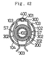
- a conventional quick connector comprises a tubular-shaped female member 100 which includes a receiving tube 102 having a receiving opening 101, a tubular-shaped male member 200 which includes a ring-shaped engager projection 201 projected in the centrifugal directions and an engager tube 202, a "C" shaped engager member 300 disposed in the receiving tube 102 of the female member 100.
- the engager member 300 is inserted into the receiving tube 102 through an entry 103 to rigidly fix a middle portion 301 to the receiving tube 102 by a rivet 400.
- the engager member 300 includes a tapered stopper 302 whose diameter can be increased.
- the tapered stopper 302 is tapered from one end to the other end in the axial direction, and the one end 302a has a small diameter and the other end 302b has a large diameter.
- the male member 200 is inserted into the receiving tube 102 of the female member 100 in the direction of the arrow "S8" through the opened flange 101, and the engager projection 201 of the male member 200 is pressed against the stopper 302 on the inner surfaces. Accordingly, the stopper 302 are deformed in the centrifugal direction (e.g., in the direction of the arrow "S7", shown in Figure 42) so as to increase the diameter.
- the engager projection 201 goes over the engager member 300, and it is disposed in the inner side with respect to the engager member 300.
- the stopper 302 of the engager member 300 whose diameter has been increased is restored to its original shape by its own elasticity in the direction reducing the diameter, thereby engaging the engager projection 201 with the engager member 300.
- the male member 200 is connected to the female member 100.
- the other conventional quick connector comprises a female member 100 which includes a a receiving tube 102 having a receiving opening 101 on one end in the axial direction, a male member 200 which includes a ring-shaped engager projection 201 projected in the centrifugal directions with a tapered surface 203 and an engager tube 202, a "U" shaped engager member 300 bent at the middle portion 301 so that one end portion 303 faces to the other end portion 303.
- a female member 100 which includes a a receiving tube 102 having a receiving opening 101 on one end in the axial direction
- a male member 200 which includes a ring-shaped engager projection 201 projected in the centrifugal directions with a tapered surface 203 and an engager tube 202, a "U" shaped engager member 300 bent at the middle portion 301 so that one end portion 303 faces to the other end portion 303.
- the middle portion 301 of the engager member 300 is outwardly projected from the entry 103, and the both end portions 303 of the engager member 300 are outwardly projected from a retainer 104. Therefore, the middle portion 301 and the both end portions 303 of the engager member 300 is likely to collide or interfere with the other component members, and the engager member 300 is likely to come off.
- the quick connector is disclosed in Japanese Patent Application No. 109419/1990.
- the quick connector requires a clearance C1 in the radial directions between the engager member 300 and the inner peripheral surface of the receiving tube 102 since the tapered stopper 302 of the engager member 300 is extended in the receiving tube 102.
- the clearance C1 is small, the diameter of the tapered stopper 302 of the engager member 300 cannot be fully increased.
- the clearance C1 is large, the engager member 300 is largely displaced with respect to the receiving tube 102.
- the engager member 300 deteriorates the smooth insertion of the male member 200. Furthermore, the satisfactory diameter enlargement of the tapered stopper 302 is also deteriorated.
- the present invention was completed to overcome the above-mentioned disadvantage.
- It is an object of the present invention is to provide a quick connector which solves the disadvantage caused by that the engager member collides or interferes with the other component members, and which solves the large displacement between the engager member and the receiving tube. Hence, it is possible to obtain the smooth insertion of the male member and the satisfactory diameter enlargement of the tapered stopper of the engager member.
- One type of quick connector according to the present invention comprises a tubular-shaped female member having an opened flange which is projected in the centripetal directions and installed at an opening end on one side in the axial direction, and an annular-shaped concave which is adjacent to and inside the opened flange and whose inner diameter is larger than that of the opened flange; a tubular-shaped male member which has a ring-shaped engager projection projected in the centrifugal directions at the predetermined distance from the top end, and which is inserted into the annular-shaped concave through the opened flange; an engager member which is hold in the annular-shaped concave of the female member, and has the spring elasticity for connecting the female member and the male member inserted into the annular-shaped concave.
- the engager member comprises a "C" ring-shaped and tapered stopper whose diameter can be increased in the annular-shaped concave, and which has the smaller diameter ends having the small diameter at the inner side of the female member and having the large diameter at the side of the opened flange to engage the engager projection, and which has the larger diameter ends having the diameter larger than that of the opened flange of the female member to face the inside end surface of the opened flange; a regulator which is installed in the axial direction to the stopper, and which is projected in the centrifugal directions than do the larger diameter ends of the stopper, and which is brought into contact with the inner peripheral surface of the annular-shaped concave to regulate the displacement in the radial direction of the stopper; and a linkage for connecting the stopper and the regulator.
- the male member is relatively inserted into the annular-shaped concave of the female member through the opened flange, and the engager projection of the male member is pressed against the stopper of the engager member on the inner surfaces. Accordingly, the stopper is deformed in the cetrifugal directions so as to increase the diameter.
- the engager projection of the male member goes over the stopper of the engager member, and it is disposed in the inner side with respect to the engager member.
- the stopper of the engager member whose diameter has been increased is restored to its original shape by its own elasticity in the direction reducing the diameter, thereby engaging the engager projection of the male member with the smaller diameter ends of the stopper of the engager member.
- the male member is connected to the female member.
- the engager member adapted for connecting them is accommodated in the annular-shaped concave of the female member. Hence, the engager member hardly collides or interferes with the other component members.
- the regulator of the engager member is projected in the centrifugal directions than do the larger diameter ends of the stopper before the engaging tube of the male member is inserted into the annular-shaped concave of the female member. Consequently, the regulator is likely to be brought into contact with the inner peripheral surface of the annular-shaped concave of the female member, and thereby the stopper can be prevented from displacing in the radial directions.
- the diameter of the stopper of the engager member is fully increased, and there can be secured the sufficient clearance between the annular-shaped concave and the stopper so that the engager projection of the male member goes over the stopper of the engager member.
- the stopper of the engager member can be displaced less or prevented from displacing in the radial directions relatively with respect to the annular-shaped concave of the female member.
- Another type of quick connector comprises a tubular-shaped female member having an opened flange which is projected in the centripetal directions and installed at an opening end on one side in the axial direction, and an annular-shaped concave which is adjacent to and inside the opened flange and whose inner diameter is larger than that of the opened flange; a tubular-shaped male member which has a ring-shaped engager projection projected in the centrifugal directions at the predetermined distance from the top end, and which is inserted into the annular-shaped concave through the opened flange; an engager member which is hold in the annular-shaped concave of the female member, and has the spring elasticity for connecting the female member and the male member inserted into the annular-shaped concave.
- the engager member comprises a "C" ring-shaped and tapered stopper whose diameter can be increased in the annular-shaped concave, and which has the smaller diameter ends having the small diameter at the inner side of the female member and having the large diameter at the side of the opened flange to engage the engager projection, and which has the larger diameter ends having the diameter larger than that of the opened flange of the female member to face the inside end surface of the opened flange; a regulator having a pair of arms whose diameter can be reduced, and which is installed in the axial direction to the stopper, and which is projected in the centrifugal directions than do the larger diameter ends of the stopper, and which is brought into contact with the inner peripheral surface of the annular-shaped concave to regulate the displacement in the radial direction of the stopper; and a linkage for connecting the stopper and the regulator.
- the engager member is inserted through the opened flange of the female member by reducing the diameter of the stopper and the regulator.
- the regulator of the engager member has a pair of arms whose diameter can be reduced.
- a pair of arms are approached each other so as to decrease the diameter, and then the diameter of the "C" ring-shaped stopper is reduced. Therefore, in this type of quick connector, it is unnecessary to detachably install a tube which has the opened flange at one side in the axial direction so that the engager member is installed in the annular-shaped concave of the female member. It is possible to form the female member integrally, so the construction of the female member comes to be compact.
- the other type of quick connector comprises a tubular-shaped female member having an opened flange which is projected in the centripetal directions and installed at an opening end on one side in the axial direction, and an annular-shaped concave which is adjacent to and inside the opened flange and whose inner diameter is larger than that of the opened flange; a tubular-shaped male member which has a ring-shaped engager projection projected in the centrifugal directions at the predetermined distance from the top end, and which is inserted into the annular-shaped concave through the opened flange; an engager member which is hold in the annular-shaped concave of the female member, and has the spring elasticity for connecting the female member and the male member inserted into the annular-shaped concave.
- the engager member comprises a "C" ring-shaped larger diameter ends which are opposed to the inside end surface of the opened flange of the female member, and which are brought into contact with the inner peripheral surface of the annular-shaped concave, and which has the outer diameter being larger than the opening diameter of the opened flange and being almost equal to the inner diameter of the annular-shaped concave; plural tapered walls which are arranged in the circumferential direction, and which are tapered coaxially with respect to the "C" ring-shaped larger diameter ends from the "C” ring-shaped larger diameter ends to the inner side of female member, and which has the smaller diameter ends having the inner diameter smaller than the outer diameter of the engager projection of the male member to engage the engager projection; at least one of linkages for extending from the "C" ring-shaped larger diameter ends to the smaller diameter ends to connect tapered walls and having a top wall which is extended from the "C" ring-shaped larger diameter ends to the smaller diameter ends in parallel to the axis and in which both peripheral ends are brought
- the male member With respect to the female member holding the engager member in its annular-shaped concave, the male member is relatively inserted into the annular-shaped concave of the female member through the opened flange, and the engager projection of the male member is pressed against the engager member on the inner peripheral surfaces of the tapered walls. Accordingly, the tapered walls are deformed elastically so as to warp radially outwardly at the smaller diameter ends. At this moment, the engager member is brought into contact with the annular-shaped concave of the female member at the "C" ring-shaped larger diameter end, at the both peripheral ends of the top wall of the linkage, and at the peripheral end contacts of the pair of the leading walls.
- the engager member can be held securely in the annular-shaped concave of the female member and concentrically therewith. Thereby it cannot be displaced in the radial directions at all when the tapered walls of the engager member are deformed elastically by the engager projection of the male member. Accordingly, the insertion of the male member into the female member can be carried out with a remarkably good operability.
- the engager projection of the male member goes over the engager member, and it is disposed in the inner side of the female member with respect to the engager member. Then, the tapered walls which have been elastically deformed radially outwardly are restored to the original shapes by their own resilient forces.
- the male member is engaged with the smaller diameter ends of the tapered walls of the engager member at the engager projection
- the female member is engaged with the "C" ring-shaped larger diameter end of the engager member at the inside end surface of the opened flange and the inner peripheral surface of the annular-shaped concave
- the engager member is engaged with the inner peripheral surface of the annular-shaped concave of the female member at the both peripheral ends of the top wall of the linkage and at the peripheral end contacts of the leading end walls.
- the engager member adapted for connecting them is accommodated in the annular-shaped concave of the female member. Hence, the engager member hardly collides or interferes with the other component members.
- the male member and the female member can be securely prevented from moving relatively in the axial directions because the engager member is engaged with the engager projection of the male member at the smaller ends of the tapered walls, and because the engager member is engaged with the inside end surface of the opened flange of the female member at the "C" ring-shaped larger diameter end. Further, on the smaller diameter ends side of the tapered walls of the engager member, the smaller diameter ends of the tapered walls are held in the directions perpendicular to the axial direction between the linkage wall of the linkage and the leading walls which are regulated by the inner peripheral surface of the annular-shaped concave of the female member.
- the engager member can adequately receive the large axial force from the engager projection of the male member at the smaller diameter ends of the tapered walls so that it is not buckled at all.
- the engager member is brought into contact with the inner peripheral surface of the annular-shaped concave of the female member at at least both peripheral ends of the top wall of the "C" ring-shaped larger diameter end and the peripheral end contacts of the pair of the leading end walls thereof, and the tapered walls are regulated in the directions perpendicular to the axial direction by the linkage wall of the linkage and the leading walls. Consequently, the engager member cannot be moved idly or loosened.
- the female member and the male member can be firmly connected and held together by way of the engager member.
- the quick connector according to the First Preferred Embodiment comprises a female member 1 formed in a cylinder, including a receiving tube 10 and made of metal, a male member 2 formed in a cylinder and made of metal, and an engager member 3 disposed in the female member 2 and made of leaf spring steel.
- the receiving tube 10 of the female member 1 includes a first tube 14 having a female threaded portion 13, and a second tube 17 having a male threaded portion 15.
- the First tube 14 and the second tube 15 are connected detachably by screwing.
- the first tube 14 includes an opened flange 12 disposed on an opened end side in the axial direction and projecting in the centripetal directions.
- the inner peripheral surface of the opened flange 12 is adapted to form a receiving opening 11 in a simple circle.
- annular-shaped concave 10a which is disposed adjacent to the opened flange 12 and which has an inside diameter larger than the opened diameter (i.e., the inside diameter) of the opened flange 12.
- the second tube 17 includes a hose inserting groove 16 formed in a cylinder.
- a ring-shaped regulatory surface 17a In the inner peripheral surface of the second tube 17, there are formed a ring-shaped regulatory surface 17a, a ring-shaped groove 17b, a sealing surface 17c, a stepped surface 17d and a ring-shaped engaging surface 17e and a stepped surface 17f.
- On the sealing surface 17c there are held sealing rings 18, 18, a snap retainer ring 18a and a collar 19.
- the male member 2 includes a ring-shaped engager projection 20 disposed at a position away from a leading end by a predetermined distance, projecting in the centrifugal directions (e.g., in the direction of "S1"), and an engaging tube 21 disposed ahead of the engager projection 20.
- the outside diameter of the engaging tube 21 of the male member 2 corresponds to the inside diameter of the engaging surface 17e of the female member 1
- the outside diameter of the engager projection 20 corresponds to the inside diameter of the regulatory surface 17a of the female member 1.
- Figure 4 illustrates the appearance of the engager member 3.
- the engager member 3 includes a "C" ring-shaped stopper 30, a ring-shaped regulator 31 disposed adjacent to the stopper 30 in the axial direction, and a linkage 32 connecting the stopper 30 and the regulator 31 and formed in a tongue.
- the stopper 30 includes a pair of tapered walls 34, 34, an intermediate linkage 33 connecting the tapered walls 34, 34 and projections 35, 35 projecting outwardly radially at the circumferential leading ends (or the circumferential cut-off ends) of the tapered walls 34, 34.
- the engager member 3 is regulated by the opened flange 12 of the receiving tube 10 of the female member 1, and thereby it is accommodated and held in the annular-shaped concave 10a.
- the first tube 14 and the second tube 17 are separated.
- the tapered walls 34 of the engager member 3 are tapered to a smaller diameter in the direction toward the inner side of the receiving tube 10, and they are tapered to a larger diameter in the direction toward the opened flange 12.
- the inside diameter between the smaller ends 34a of the tapered walls 34 is designated by "D1,”
- the outside diameter of the engager projection 20 of the male member 2 is designated at “D2”
- “D1” is set smaller than “D2” (i.e., "D1" ⁇ "D2").
- the outside diameter of the regulator 31 of the engager member 3 is designated at "D4," and "D4" is adapted to be larger than the outside diameter between the larger diameter ends 34b of the tapered walls 34.
- the outer end 31a of the regulator 31 is projected in the centrifugal directions (e.g., in the direction of the arrow "S1") than do the larger diameter ends 34b of the tapered walls 34.
- a larger clearance "C2” between the larger diameter ends 34b of the tapered walls 34 and the annular-shaped concave 10a of the receiving tube 10
- the outer end 31a of the regulator 31 is likely to be brought into contact with the annular-shaped concave 10a of the receiving tube 10.
- the stopper 30 can be prevented from displacing in the radial directions.
- the engager member 3 is manufactured as follows. First, a spring steel plate is punched out so as to prepare a punched workpiece 4 as illustrated in Figure 5. Then, the punched workpiece 4 is bent along the bending lines 4a through 4f so as to form the substantially "C"-shaped stopper 30, and it is also bent along the bending line 32a in the linkage 32 so as to form the engager member 3 as illustrated in Figure 4.
- the thus manufactured engager member 3 is illustrated in Figures 6 through 8. As illustrated in Figure 6, linear portions 31b are formed in the regulator 31. In this First Preferred Embodiment, the regulator 31 and the stopper 30 are disposed eccentrically. As illustrated in Figures 7 and 8, there is provided a minute clearance 36 between the stopper 30 and the regulator 31 in the axial direction. It is preferred that the dimension "t1" of the minute clearance 36 is as small as possible.
- the engager member 3 can be formed of resin such as nylon, or the like.
- the engaging tube 21 of the male member 2 is first inserted into the annular-shaped concave 10a of the receiving tube 10 of the female member 1 through the opened flange 12, and the engager projection 20 of the male member 3 is pressed against the stopper 30 of the engager member 3 on the inner surfaces 34c of the tapered walls 34. Accordingly, the tapered walls 34 are deformed in the centrifugal directions (e.g., in the direction of the arrow "S1") so as to increase the diameter.
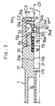
- the engager projection 20 goes over the stopper 30 of the engager member 3, and it is disposed in the inner side of the female member 1 with respect to the engager member 3. Then, the tapered walls 34 whose diameter has been increased are restored to their original shapes by its own elasticity in the direction reducing the diameter, thereby engaging the engager projection 20 with the smaller diameter ends 34a of the tapered walls 34 as illustrated in Figure 2. Finally, the male member 2 is connected to the female member 1.
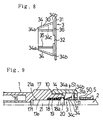
- the male member 2 and the female member 1 can be separated as follows. First, as illustrated in Figure 9, a releasing, tube 5 is inserted into the receiving tube 10 through the opened flange 12, and it is pressed onto the inner peripheral surfaces 34c of the tapered walls 34 at the leading end 50. Accordingly, the tapered walls 34 are deformed in centrifugal directions, e.g., in the direction of the arrow "S1" so as to increase the diameter, and thereby the engager projection 20 and the smaller ends 34a of the tapered walls 34 are disengaged. Under the disengagement, the male member 2 and the female member 1 can be separated apart relatively.
- the outer end 31a of the regulator 31 of the engager member 3 is projected in the centrifugal directions (e.g., in the direction of the arrow "S1") than do the larger diameter ends 34b of the tapered walls 34 before the engaging tube 21 of the male member 2 is inserted into the receiving tube 10 of the female member 1. Consequently, the outer end 31a of the regulator 31 is likely to be brought into contact with the annular-shaped concave 10a of the receiving tube 10, and thereby the stopper 30 can be prevented from displacing in the radial directions.
- the sealing rings 18, 18 maintain the sealing in the boundary area between the male member 2 and the female member 1, and accordingly a fluid can be transferred by way of the tubular male member 2 and the tubular female member 1.
- the outer peripheral surface 21a of the engaging tube 21 of the male member 2 is opposed to and supported by the engaging surface 17e of the receiving tube 10
- the outer peripheral surface of the engager projection 20 of the male member 2 is opposed to and supported by the regulatory surface 17a of the receiving tube 10. Consequently, the male member 2 and the female member 1 can be prevented from displacing relatively in the directions perpendicular to the axial direction.
- a quick connector according to a Second Preferred Embodiment of the present invention will be hereinafter described with reference to Figures 10 and 11.
- the constructions, the operations and the advantageous effects of the Second Preferred Embodiment are identical with those of the First Preferred Embodiment basically, and like component parts will be described with the same reference numerals as those of the First Preferred Embodiment.
- a regulator 61 of the engager member 3 includes two arms 62 projecting in the centrifugal directions and formed in a letter "V" shape, and an intermediate portion 63.
- the letter "V"-shaped arms 62 are disposed adjacent to or brought into contact with the annular-shaped concave 10a of the receiving tube 10.
- the leading ends (or the cut-off ends) 62c of the arms 62 are disposed on the same side as the projections 35, and the intermediate outer peripheral ends 62a (or the radially outermost portions 62a) of the arms 62 are opposed in the same direction as the direction in which the stopper 30 is deformed so as to increase the diameter.
- the quick connector of the Second Preferred Embodiment operates and produces the advantageous effects as the First Preferred Embodiment does. Additionally, when inserting the engager member 3 into the receiving tube 10 through the opened flange 12 of the female member 1 in the quick connector, the first tube 14 and the second tube 17 of the female member 1 are kept assembled, a pair of the arms 62 are approached each other so as to decrease the diameter, and then the diameter of the tapered walls 34 of the stopper 30 is reduced. In other words, before inserting the engager member 3 into the receiving tube 10, it is unnecessary to disassemble the first tube 14 and the second tube 17 of the receiving tube 10. Hence, it is possible to form the first tube 14 and the second tube 17 integrally.
- a quick connector according to a Third Preferred Embodiment of the present invention will be hereinafter described with reference to Figures 12 and 13.
- the constructions, the operations and the advantageous effects of the Third Preferred Embodiment are identical with those of the Second Preferred Embodiment basically.
- the regulator 61 includes two arms 62 projecting in the centrifugal directions, and an intermediate linkage portion 63. At the ends of the arms 62, there are further formed a first curved portion 62e and a second curved portion 62f.
- the first curved portions 62e are disposed adjacent to the outer peripheral surface of the engaging tube 21 of the male member 2, and the second curved portions 62f are disposed adjacent to the annular-shaped concave 10a of the receiving tube 10.
- the quick connector operates and produces the same advantageous effects as the Second Preferred Embodiment does in general.
- a quick connector according to a Fourth Preferred Embodiment of the present invention will be hereinafter described with reference to Figures 14 and 16.
- the constructions, the operations and the advantageous effects of the Third Preferred Embodiment are identical with those of the Second Preferred Embodiment basically.
- the regulator 61 includes two arms 62 projecting in the centrifugal directions at the ends and formed in a letter "V" shape.
- the arms 62 are adapted to have a length of "L5,” but the length "L5" can be shortened.
- the linkage 32 is bent so that it is drawn in toward the stopper 30. Accordingly, the clearance 36 between the stopper 30 and the regulator 61 is made smaller.
- a quick connector according to a Fifth Preferred Embodiment of the present invention will be hereinafter described with reference to Figures 17 and 19.
- the constructions, the operations and the advantageous effects of the Fifth Preferred Embodiment are identical with those of the Second Preferred Embodiment basically.
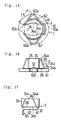
- the regulator 61 includes the two arms 62 projecting in the centrifugal directions and formed in a letter "V" shape. At each leading end of the arms 62, there is provided a grip 65 so as to extend in the axial direction (i.e., two grips 65 are provided in total for the regulator 61 of the engager member 3).
- the grips 65 are approached each other by operating manually or by a robot in the direction of the arrows "S5" illustrated in Figure 19, and thereby the regulator 61 is deformed so as to decrease the diameter. Accordingly, in the quick connector of the Fifth Preferred Embodiment, the operability is improved during the insertion of the engager member 3 into the receiving tube 10 through the opened flange 12.
- the grips 65 of the engager member 3 are extended so as to project from the opened flange 12 of the female member 1, the grips 65 can be approached each other so as to decrease the diameter of the regulator 61 by operating the portions of the grips 65 exposed to the outside. As a result, the engager member 3 can be taken out of the receiving tube 10 of the female member 1, and thereby the female member 1 and the male member 2 can be disintegrated.
- a quick connector according to a Sixth Preferred Embodiment of the present invention will be hereinafter described with reference to Figure 20.
- the constructions, the operations and the advantageous effects of the Sixth Preferred Embodiment are identical with those of the Second Preferred Embodiment basically.
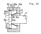
- the stopper 30 is disposed on the side of the opened flange 12 of the female member 1, and the regulator 61 is disposed on the inner side of the receiving tube 10 of the female member 1.
- the tapered walls 34 of the stopper 30 are engaged with the engager projection 20 of the male member 2 at the smaller diameter ends 34a, and they are directly and uniformly brought into contact with and engaged with the inner end surface of the opened flange 12 of the receiving tube 10 at the larger diameter ends 34b around the periphery.
- the engager member 3 can be hardly displaced in the axial direction so that the female member 1 and the male member 2 can be connected stably.
- a quick connector according to a Seventh Preferred Embodiment of the present invention will be hereinafter described with reference to Figures 21 through 25.
- the constructions, the operations and the advantageous effects of the Seventh Preferred Embodiment are identical with those of the Sixth Preferred Embodiment basically.
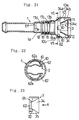
- the female member 1 is formed integrally, and it is provided with the receiving tube 10 at an end of the shaft 1a in the axial direction, receiving tube 10 which is formed by increasing the diameter at the end.
- the engager member 3 is disposed in the receiving tube 10 through the opened flange 12 by deforming the stopper 30 and the regulator 61 so as to decrease the diameters.
- the regulator 61 of the stopper 30 includes two arms 62 projecting in the centrifugal directions and formed substantially in a letter "U" shape. As best shown in Figures 23 and 25, the arms 62 are formed integrally with the stopper 30.
- the arms 62 are connected to the stopper 30 by way of two linkages 32 which are extended from the projections 35 at the leading ends of the tapered walls 34 in the axial direction.
- the snap retainer ring 18 is made from resin, and it is fixed in the female member 1 by press-fitting itself into the ring-shaped groove 17b of the female member 1.
- the annular-shaped concave 10a is formed in a stepped surface 10b on the innermost side.
- a quick connector according to an Eighth Preferred Embodiment of the present invention will be hereinafter described with reference to Figures 26 through 31.
- the constructions, the operations and the advantageous effects of the Eighth Preferred Embodiment are identical with those of the Sixth Preferred Embodiment basically.
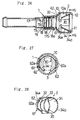
- the female member 1 is formed integrally, and the engager member 3 is disposed in the receiving tube 10 through the opened flange 12 by deforming the stopper 30 and the regulator 61 so as to decrease the diameters.
- the regulator 61 of the stopper 30 includes two arms 62 projecting in the centrifugal directions and formed substantially in a letter "U" shape.
- the arms 62 are formed integrally with the stopper 30. Specifically speaking, on the side of the smaller diameter ends 34a of the tapered walls 34 of the stopper 30, the arms 62 are connected to the stopper 30 by way of a linkage 32 which is extended from an intermediate linkage 33 disposed on the stopper 30 in the axial direction.
- the stopper 30 of the engager member 3 is disposed on the inner side of the opened flange 12, and the regulator 61 is disposed on the inner side of the receiving tube 10 in the same manner as the Sixth Preferred Embodiment described above. Accordingly, the tapered walls 34 of the stopper 30 are engaged with the engager projection 20 of the male member 2 at the smaller diameter ends 34a, and they are directly and uniformly brought into contact with and engaged with the inner end surface of the opened flange 12 of the receiving tube 10 at the larger diameter ends 34b around, the periphery.
- the engager member 3 can be hardly displaced in the axial direction so that the female member 1 and the male member 2 can be connected stably.
- a quick connector according to a Ninth Preferred Embodiment of the present invention will be hereinafter described with reference to Figures 32 through 39.
- the quick connector comprises the female member 1 and the male member 2 whose constructions are identical with those of the Seventh Preferred Embodiment, and they will not be described herein.
- the engager member 3 has a "C” ring-shaped overall configuration, and it is formed by cutting and bending a thin leaf spring made of stainless steel.
- the engager member 3 includes a "C" ring-shaped larger diameter end 71, a pair of arc-shaped tapered walls 72, 72, a linkage 73, and a pair of leading end (or cut-off end) walls 74, 74.
- the "C” ring-shaped larger diameter end 71 of the engager member 3 has an outside diameter which is larger than the opened diameter (i.e., the inside diameter) of the opened flange 12 of the female member 1 and which is substantially equal to the inside diameter of the annular-shaped concave 10a.
- the "C” ring-shaped larger diameter end 71 of the engager member 3 is brought into contact with the inside end surface of the opened flange 12 and the inner peripheral surface of the annular-shaped concave 10a.
- the pair of the arc-shaped tapered walls 72, 72 of the engager member 3 are formed integrally with the "C" ring-shaped larger diameter end 71 on the larger diameter side, and they reduce the diameter coaxially with the "C" ring-shaped larger diameter end 71 as they extend in the direction toward the inner side of the female member 1.
- the pair of the arc-shaped tapered walls 72, 72 have an inside diameter which is smaller than the outside diameter of the engager projection 20 of the male member 2 on the side of the smaller diameter ends, and they have an inside diameter which is substantially equal to the outside diameter of the engaging tube 21 of the male member 2 on the side of the smaller ends.
- the linkage 73 of the engager member 3 is extended from the "C" ring-shaped larger diameter end 71 to the smaller diameter ends of the arc-shaped tapered walls 72, 72 so as to link the pair of the arc-shaped tapered walls 72, 72.
- the linkage 73 includes an arc-shaped top wall 73a, and a pair of linkage walls 73b, 73b formed in a substantially triangular plate.
- the arc-shaped top wall 73a is brought into contact with the inner peripheral surface of the annular-shaped concave 10a which has the inside diameter substantially equal to the outside diameter of the "C" ring-shaped larger diameter end 71.
- the linkage walls 73b, 73b are formed by bending the arc-shaped top wall 73a at the circumferential ends (or the diametric ends), and they are extended parallel each other so that they are connected to one of the circumferential ends (or the cut-off ends) of the pair of the arc-shaped tapered walls 72, 72.
- the pair of the leading end walls 74, 74 of the engager member 3 are extended from the circumferential ends (or the cut-off ends) of the "C" ring-shaped larger diameter end 71 to the smaller diameter ends of the arc-shaped tapered walls 72, 72, and they are connected to another one of the circumferential ends (or the cut-off ends) of the pair of the arc-shaped tapered walls 72, 72.
- the leading end walls 74, 74 are formed in a substantially triangular plate, and they are extended symmetrically each other and parallelly with the linkage walls 73b, 73b.
- the pair of the leading end walls 74, 74 include a pair of peripheral end contacts 74a, 74a.
- the outside diameter of the "C" ring-shaped larger diameter end 71 of the engager member 3 is set so that it is slightly larger than the annular-shaped concave 10a of the female member 1.
- the engager member 3 is inserted into the annular-shaped concave 10a through the opened flange 12 while its diameter is reduced by elastically deforming, namely by approaching the pair of the leading end walls 74, 74 each other.
- the engager member 3 is put back into its original diameter by its own resilient force when the insertion is completed, and thereby it is engaged in the annular-shaped concave 10a with the outer peripheral surfaces of the arc-shaped top wall 73a and the pair of the peripheral end contacts 74a, 74a brought into contact with the inner peripheral surface of the annular-shaped concave 10a.
- the engaging tube 21 of the male member 2 is inserted into the annular-shaped concave 10a of the receiving tube 10 of the female member 1 through the opened flange 12, and the engager projection 20 of the male member 2 is pressed against the inner peripheral surfaces of the pair of the arc-shaped tapered walls 32, 32. Accordingly, the pair of the tapered walls 34, 34 are deformed elastically so as to warp radially outwardly at the smaller diameter ends as illustrated in Figure 33.
- the engager member 3 is brought into contact with the annular-shaped concave 10a at the "C" ring-shaped larger diameter end 71, at the arc-shaped top wall 33a of the linkage 73 and at the peripheral end contacts 74a, 74a of the pair of the leading walls 74, 74.
- the engager member 3 can be held securely in the annular-shaped concave 10a of the female member 1 and concentrically therewith.
- the engager member 3 can be prevented from moving into the inside of the female member 1 because the linkage 73 and the leading ends 74 are brought into contact with the stepped surface 10b of the annular-shaped concave 10a at the ends, and thereby it cannot be displaced in the radial directions and in the axial directions at all when the pair of the arc-shaped tapered walls 72, 72 are deformed elastically by the projection 20 of the male member 2. Accordingly, the insertion of the male member 2 into the female member 1 can be carried out with a remarkably good operability.
- the male member 2 is engaged with the smaller diameter ends of the arc-shaped tapered walls 72, 72 of the engager member 3 at the engager projection 20, the female member 1 is engaged with the "C" ring-shaped larger diameter end 71 of the engager member 3 at the inside end surface of the opened flange 12 and the inner peripheral surface of the annular-shaped concave 10a, and the engager member 3 is engaged with the inner peripheral surface of the annular-shaped concave 10a of the female member 1 at the arc-shaped top wall 73a of the linkage 73 and at the peripheral end contacts 74a, 74a of the leading ends walls 74 and 74.
- the male member 2 is connected to the female member 1.
- the engager member 3 adapted for connecting them is accommodated in the annular-shaped concave 10a of the female member 1. Hence, the engager member 3 hardly collides or interferes with the other component members.
- the male member 2 and the female member 1 can be securely prevented from moving relatively in the axial directions because the engager member 3 is engaged with the engager projection 20 of the male member 2 at the smaller ends of the pair of the arc-shaped tapered walls 72, 72, and because the engager member 3 is engaged with the inside end surface of the opened flange 12 of the female member 1 at the "C" ring-shaped larger diameter end 71.
- the smaller diameter ends of the arc-shaped tapered walls 72, 72 are held in the directions perpendicular to the axial direction between the linkage wall 73b of the linkage 73 and the leading walls 74, 74 which are regulated by the inner peripheral surface of the annular-shaped concave 10a of the female member 1.
- the engager member 3 can adequately receive the large axial force from the engager projection 20 of the male member 2 at the smaller diameter ends of the arc-shaped tapered walls 72, 72 so that it is not buckled at all.
- the engager member 3 is brought into contact with the inner peripheral surface of the annular-shaped concave 10a of the female member 1 at the "C" ring-shaped larger diameter ends 71, the arc-shaped top wall 73a of the linkage 73 and the peripheral end contacts 74a, 74a of the pair of the leading end walls 74, 74 thereof, and the pair of the arc-shaped tapered walls 72, 72 are regulated in the directions perpendicular to the axial direction by the linkage wall 73b of the linkage 73 and the leading walls 74, 74. Consequently, the engager member 3 cannot be moved idly or loosened.
- the female member 1 and the male member 2 can be firmly connected and held together by way of the engager member 3.
- the outer configuration of the "C" ring-shaped larger diameter end 71 is formed in a simple circle.
- the engager member 3 can be freely inserted into the female member 1 through the opened flange 12 by deforming itself so as to reduce the diameter. Accordingly, the engager member 3 can be disposed in the female member 1 with an improved operability.
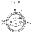
- the opened flange 12 of the female member 1 can be formed in a simple circle as illustrated in Figure 35. Accordingly, the female member 1 is manufactured with a reduced cost.
- a releasing jig 4 When separating the male member 2 and the female member 1, a releasing jig 4 is moved into the inner side of the female member 1 as illustrated in Figure 34, and it is pressed onto the inner peripheral surfaces of the arc-shaped tapered walls 72, 72 in order to elastically deform them. Accordingly, the engager projection 20 and the arc-shaped tapered walls 74, 74 are disengaged. Under the disengagement, the male member 2 and the female member 1 can be separated apart relatively.
- a quick connector according to a Tenth Preferred Embodiment of the present invention will be hereinafter described with reference to Figures 40 and 41.
- the constructions, the operations arid the advantageous effects of the Tenth Preferred Embodiment are identical with those of the Ninth Preferred Embodiment basically except that an engager member 3' is modified in the configuration.
- the engager member 3' has the same constructions as those of the engager member 3 of the Ninth Preferred Embodiment except that it includes three arc-shaped tapered walls 72 instead of the two of them provided to the engager member 3 of the Ninth Preferred Embodiment, and that it includes two linkages 73, 73 instead of the one provided thereto.
- the quick connector of the Tenth Preferred Embodiment operates and effects advantages similarly to the Ninth Preferred Embodiment.
- a groove 73c can be formed in the arc-shaped top walls 73a, 73a of the linkages 73, 73, groove 73c which extends from the smaller ends of the arc-shaped tapered walls 72, 72 to the larger diameter ends in the axial direction.
- the engager member 3' can be upgraded in the overall diameter reducing ability.
- the engager member 3' can be disposed in the annular-shaped concave 10a through the opened flange 12 of the female member 1 with a further improved operability.
- the top walls 73a of the linkage 73 of the engager member 3 or 3' are formed in an arc.
- the present invention is not limited thereto.
- the top walls 73a can be formed in a flat surface, and they are can be brought into contact with the inner peripheral surface of the annular-shaped concave 10a at the circumferential ends (or the diametric ends).
- the female member 1 can be formed of resin such as nylon, polypropylene, or the like
- the engager member 3 and 3' can be formed of resin having a spring-like elasticity, e.g., nylon, or the like.
- a quick connector comprises a tubular-shaped female member, a tubular-shaped male member, and an engager member which comprises a "C" ring-shaped and tapered stopper whose diameter can be increased in said annular-shaped concave, and which has the smaller diameter ends having the small diameter at the inner side of said female member and having the large diameter at the side of said opened flange to engage said engager projection, and which has the larger diameter ends having the diameter larger than that of said opened flange of said female member to face the inside end surface of said opened flange; a regulator which is installed in the axial direction to said stopper, and which is projected in the centrifugal directions than do the larger diameter ends of said stopper, and which is brought into contact with the inner peripheral surface of said annular-shaped concave to regulate the displacement in the radial direction of said stopper; and a linkage for connecting said stopper and said regulator.
- the smooth insertion of the male member and the satisfactory diameter enlargement of the stopper can be obtained.
Landscapes
- Engineering & Computer Science (AREA)
- General Engineering & Computer Science (AREA)
- Mechanical Engineering (AREA)
- Quick-Acting Or Multi-Walled Pipe Joints (AREA)
Abstract
Description
- The present invention relates to a quick connector having a male member and a female member for piping for connecting hoses or pipes which are employed to transfer a fluid, such as gasoline, oil, water, air and the like, especially relates to a quick connector having a simple engager member.
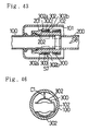
- As disclosed in Figures 42 and 43, a conventional quick connector comprises a tubular-shaped
female member 100 which includes areceiving tube 102 having a receiving opening 101, a tubular-shaped male member 200 which includes a ring-shaped engager projection 201 projected in the centrifugal directions and anengager tube 202, a "C"shaped engager member 300 disposed in thereceiving tube 102 of thefemale member 100. This is described in U.S.P. 3,929,357. As illustrated in Figure 32, theengager member 300 is inserted into thereceiving tube 102 through anentry 103 to rigidly fix amiddle portion 301 to thereceiving tube 102 by a rivet 400. The engagermember 300 includes atapered stopper 302 whose diameter can be increased. Thetapered stopper 302 is tapered from one end to the other end in the axial direction, and the one end 302a has a small diameter and the other end 302b has a large diameter. - The
male member 200 is inserted into thereceiving tube 102 of thefemale member 100 in the direction of the arrow "S8" through the openedflange 101, and theengager projection 201 of themale member 200 is pressed against thestopper 302 on the inner surfaces. Accordingly, thestopper 302 are deformed in the centrifugal direction (e.g., in the direction of the arrow "S7", shown in Figure 42) so as to increase the diameter. Thus, theengager projection 201 goes over the engagermember 300, and it is disposed in the inner side with respect to the engagermember 300. Then, thestopper 302 of theengager member 300 whose diameter has been increased is restored to its original shape by its own elasticity in the direction reducing the diameter, thereby engaging theengager projection 201 with theengager member 300. Finally, themale member 200 is connected to thefemale member 100. - As disclosed in Figures 44 and 45, the other conventional quick connector comprises a
female member 100 which includes a a receivingtube 102 having a receiving opening 101 on one end in the axial direction, amale member 200 which includes a ring-shaped engager projection 201 projected in the centrifugal directions with atapered surface 203 and anengager tube 202, a "U" shaped engagermember 300 bent at themiddle portion 301 so that oneend portion 303 faces to theother end portion 303. This is described in Japanese Laid-Open Patent Publication No. 225290/1983. - As illustrated in Figures 42 and 45, in the above conventional quick connector, the
middle portion 301 of theengager member 300 is outwardly projected from theentry 103, and the bothend portions 303 of theengager member 300 are outwardly projected from aretainer 104. Therefore, themiddle portion 301 and the bothend portions 303 of theengager member 300 is likely to collide or interfere with the other component members, and theengager member 300 is likely to come off. - As illustrated in Figure 46, inventors have found a new type of quick connector in which the "C" shaped
engager member 300 is installed in thereceiving tube 102 of thefemale member 100. The quick connector is disclosed in Japanese Patent Application No. 109419/1990. The quick connector requires a clearance C1 in the radial directions between theengager member 300 and the inner peripheral surface of thereceiving tube 102 since thetapered stopper 302 of theengager member 300 is extended in thereceiving tube 102. When the clearance C1 is small, the diameter of thetapered stopper 302 of theengager member 300 cannot be fully increased. When the clearance C1 is large, theengager member 300 is largely displaced with respect to thereceiving tube 102. Therefore, when themale member 200 is inserted into thereceiving tube 102 of thefemale member 100, theengager member 300 deteriorates the smooth insertion of themale member 200. Furthermore, the satisfactory diameter enlargement of thetapered stopper 302 is also deteriorated. - The present invention was completed to overcome the above-mentioned disadvantage.
- It is an object of the present invention is to provide a quick connector which solves the disadvantage caused by that the engager member collides or interferes with the other component members, and which solves the large displacement between the engager member and the receiving tube. Hence, it is possible to obtain the smooth insertion of the male member and the satisfactory diameter enlargement of the tapered stopper of the engager member.
- One type of quick connector according to the present invention comprises a tubular-shaped female member having an opened flange which is projected in the centripetal directions and installed at an opening end on one side in the axial direction, and an annular-shaped concave which is adjacent to and inside the opened flange and whose inner diameter is larger than that of the opened flange; a tubular-shaped male member which has a ring-shaped engager projection projected in the centrifugal directions at the predetermined distance from the top end, and which is inserted into the annular-shaped concave through the opened flange; an engager member which is hold in the annular-shaped concave of the female member, and has the spring elasticity for connecting the female member and the male member inserted into the annular-shaped concave. The engager member comprises a "C" ring-shaped and tapered stopper whose diameter can be increased in the annular-shaped concave, and which has the smaller diameter ends having the small diameter at the inner side of the female member and having the large diameter at the side of the opened flange to engage the engager projection, and which has the larger diameter ends having the diameter larger than that of the opened flange of the female member to face the inside end surface of the opened flange; a regulator which is installed in the axial direction to the stopper, and which is projected in the centrifugal directions than do the larger diameter ends of the stopper, and which is brought into contact with the inner peripheral surface of the annular-shaped concave to regulate the displacement in the radial direction of the stopper; and a linkage for connecting the stopper and the regulator.
- The male member is relatively inserted into the annular-shaped concave of the female member through the opened flange, and the engager projection of the male member is pressed against the stopper of the engager member on the inner surfaces. Accordingly, the stopper is deformed in the cetrifugal directions so as to increase the diameter. Thus, the engager projection of the male member goes over the stopper of the engager member, and it is disposed in the inner side with respect to the engager member. Then, the stopper of the engager member whose diameter has been increased is restored to its original shape by its own elasticity in the direction reducing the diameter, thereby engaging the engager projection of the male member with the smaller diameter ends of the stopper of the engager member. Finally, the male member is connected to the female member. Under the connection thus established, even when one tries to separate the male member and female member relatively, they cannot be separated apart because the smaller diameter ends of the stopper of the engager member and the engager projection of the male member are engaged with each other, and because the larger diameter ends of the stopper and the inside end surface of the opened flange are engaged with each other directly or indirectly.
- When the female member and the male member are connected, the engager member adapted for connecting them is accommodated in the annular-shaped concave of the female member. Hence, the engager member hardly collides or interferes with the other component members.
- The regulator of the engager member is projected in the centrifugal directions than do the larger diameter ends of the stopper before the engaging tube of the male member is inserted into the annular-shaped concave of the female member. Consequently, the regulator is likely to be brought into contact with the inner peripheral surface of the annular-shaped concave of the female member, and thereby the stopper can be prevented from displacing in the radial directions. Hence, when the male member is connected to the female member, the diameter of the stopper of the engager member is fully increased, and there can be secured the sufficient clearance between the annular-shaped concave and the stopper so that the engager projection of the male member goes over the stopper of the engager member. At the same time, the stopper of the engager member can be displaced less or prevented from displacing in the radial directions relatively with respect to the annular-shaped concave of the female member. As a result, it is possible to ensure the smooth insertion of the male member into the female member and the satisfactory diameter enlargement of the stopper of the engager member.
- Another type of quick connector according to the present invention comprises a tubular-shaped female member having an opened flange which is projected in the centripetal directions and installed at an opening end on one side in the axial direction, and an annular-shaped concave which is adjacent to and inside the opened flange and whose inner diameter is larger than that of the opened flange; a tubular-shaped male member which has a ring-shaped engager projection projected in the centrifugal directions at the predetermined distance from the top end, and which is inserted into the annular-shaped concave through the opened flange; an engager member which is hold in the annular-shaped concave of the female member, and has the spring elasticity for connecting the female member and the male member inserted into the annular-shaped concave. The engager member comprises a "C" ring-shaped and tapered stopper whose diameter can be increased in the annular-shaped concave, and which has the smaller diameter ends having the small diameter at the inner side of the female member and having the large diameter at the side of the opened flange to engage the engager projection, and which has the larger diameter ends having the diameter larger than that of the opened flange of the female member to face the inside end surface of the opened flange; a regulator having a pair of arms whose diameter can be reduced, and which is installed in the axial direction to the stopper, and which is projected in the centrifugal directions than do the larger diameter ends of the stopper, and which is brought into contact with the inner peripheral surface of the annular-shaped concave to regulate the displacement in the radial direction of the stopper; and a linkage for connecting the stopper and the regulator. The engager member is inserted through the opened flange of the female member by reducing the diameter of the stopper and the regulator.
- In the above mentioned quick connector, the regulator of the engager member has a pair of arms whose diameter can be reduced. In other words, when inserting the engager member into the annular-shaped concave through the opened flange of the female member, a pair of arms are approached each other so as to decrease the diameter, and then the diameter of the "C" ring-shaped stopper is reduced. Therefore, in this type of quick connector, it is unnecessary to detachably install a tube which has the opened flange at one side in the axial direction so that the engager member is installed in the annular-shaped concave of the female member. It is possible to form the female member integrally, so the construction of the female member comes to be compact.
- The other type of quick connector according to the present invention comprises a tubular-shaped female member having an opened flange which is projected in the centripetal directions and installed at an opening end on one side in the axial direction, and an annular-shaped concave which is adjacent to and inside the opened flange and whose inner diameter is larger than that of the opened flange; a tubular-shaped male member which has a ring-shaped engager projection projected in the centrifugal directions at the predetermined distance from the top end, and which is inserted into the annular-shaped concave through the opened flange; an engager member which is hold in the annular-shaped concave of the female member, and has the spring elasticity for connecting the female member and the male member inserted into the annular-shaped concave. The engager member comprises a "C" ring-shaped larger diameter ends which are opposed to the inside end surface of the opened flange of the female member, and which are brought into contact with the inner peripheral surface of the annular-shaped concave, and which has the outer diameter being larger than the opening diameter of the opened flange and being almost equal to the inner diameter of the annular-shaped concave; plural tapered walls which are arranged in the circumferential direction, and which are tapered coaxially with respect to the "C" ring-shaped larger diameter ends from the "C" ring-shaped larger diameter ends to the inner side of female member, and which has the smaller diameter ends having the inner diameter smaller than the outer diameter of the engager projection of the male member to engage the engager projection; at least one of linkages for extending from the "C" ring-shaped larger diameter ends to the smaller diameter ends to connect tapered walls and having a top wall which is extended from the "C" ring-shaped larger diameter ends to the smaller diameter ends in parallel to the axis and in which both peripheral ends are brought into contact with the inner peripheral surface of the annular-shaped concave having the diameter almost equal to the outer diameter of the "C" ring-shaped larger diameter ends, and a pair of linkage walls which are extended downwardly and in parallel from the both peripheral ends of the top wall and in which each linkage wall is connected to each one peripheral end of the tapered walls; a pair of leading walls which are extended from the "C" ring-shaped larger diameter ends to the smaller diameter ends and in which each leading wall is connected to the other peripheral end of the tapered walls, and which has peripheral end contacts extended from the "C" ring-shaped larger diameter ends to the smaller diameter ends and brought into contact with the inner peripheral surface of the annular-shaped concave whose diameter is equal to the outer diameter of the "C" ring-shaped larger diameter ends.
- With respect to the female member holding the engager member in its annular-shaped concave, the male member is relatively inserted into the annular-shaped concave of the female member through the opened flange, and the engager projection of the male member is pressed against the engager member on the inner peripheral surfaces of the tapered walls. Accordingly, the tapered walls are deformed elastically so as to warp radially outwardly at the smaller diameter ends. At this moment, the engager member is brought into contact with the annular-shaped concave of the female member at the "C" ring-shaped larger diameter end, at the both peripheral ends of the top wall of the linkage, and at the peripheral end contacts of the pair of the leading walls. Thus, the engager member can be held securely in the annular-shaped concave of the female member and concentrically therewith. Thereby it cannot be displaced in the radial directions at all when the tapered walls of the engager member are deformed elastically by the engager projection of the male member. Accordingly, the insertion of the male member into the female member can be carried out with a remarkably good operability.
- When the male member is further inserted into the female member, the engager projection of the male member goes over the engager member, and it is disposed in the inner side of the female member with respect to the engager member. Then, the tapered walls which have been elastically deformed radially outwardly are restored to the original shapes by their own resilient forces. Accordingly, the male member is engaged with the smaller diameter ends of the tapered walls of the engager member at the engager projection, the female member is engaged with the "C" ring-shaped larger diameter end of the engager member at the inside end surface of the opened flange and the inner peripheral surface of the annular-shaped concave, and the engager member is engaged with the inner peripheral surface of the annular-shaped concave of the female member at the both peripheral ends of the top wall of the linkage and at the peripheral end contacts of the leading end walls. As a result, the male member is connected to the female member.
- When the female member and the male member are connected, the engager member adapted for connecting them is accommodated in the annular-shaped concave of the female member. Hence, the engager member hardly collides or interferes with the other component members.
- The male member and the female member can be securely prevented from moving relatively in the axial directions because the engager member is engaged with the engager projection of the male member at the smaller ends of the tapered walls, and because the engager member is engaged with the inside end surface of the opened flange of the female member at the "C" ring-shaped larger diameter end. Further, on the smaller diameter ends side of the tapered walls of the engager member, the smaller diameter ends of the tapered walls are held in the directions perpendicular to the axial direction between the linkage wall of the linkage and the leading walls which are regulated by the inner peripheral surface of the annular-shaped concave of the female member. As a result, when a large axial force is exerted to the female member and the male member so as to separate them apart, the engager member can adequately receive the large axial force from the engager projection of the male member at the smaller diameter ends of the tapered walls so that it is not buckled at all.
- In addition, the engager member is brought into contact with the inner peripheral surface of the annular-shaped concave of the female member at at least both peripheral ends of the top wall of the "C" ring-shaped larger diameter end and the peripheral end contacts of the pair of the leading end walls thereof, and the tapered walls are regulated in the directions perpendicular to the axial direction by the linkage wall of the linkage and the leading walls. Consequently, the engager member cannot be moved idly or loosened.
- Hence, the female member and the male member can be firmly connected and held together by way of the engager member.
- A more complete appreciation of the present invention and many of its advantages will be readily obtained as the same becomes better understood by reference to the following detailed description when considered in connection with the accompanying drawings and detailed specification, all of which forms a part of the disclosure:
- Figure 1 is a cross-sectional view for showing the principal part of the female member.
- Figure 2 is a cross-sectional view for showing the condition that the male member is connected to the female member.
- Figure 3 is a Y1 to Y1 cross-sectional view of Figure 2.
- Figure 4 is a diagonal view for showing the engager member.
- Figure 5 is a development for showing the engager member.
- Figure 6 is a front view for showing the engager member.
- Figure 7 is a plane view for showing the engager member.
- Figure 8 is a side view for showing the engager member.
- Figure 9 is a cross-sectional view for showing the principle part when the male member is separated from the female member.
- Figure 10 is a Y2 to Y2 cross-sectional view of Figure 11.
- Figure 11 is a cross-sectional view for showing the principle part according to the Second Preferred Embodiment.
- Figure 12 is a front view for showing the engager member according to the Third Preferred Embodiment.
- Figure 13 is a side view for showing the engager member according to the Third Preferred Embodiment.
- Figure 14 is a plane view for showing the engager member according to the Fourth Preferred Embodiment.
- Figure 15 is a front view for showing the engager member according to the Fourth Preferred Embodiment.
- Figure 16 is a side view for showing the engager member according to the Fourth Preferred Embodiment.
- Figure 17 is a plane view for showing the engager member according to the Fifth Preferred Embodiment.
- Figure 18 is a Y4 to Y4 front view of Figure 19 for showing the engager member according to the Fifth Preferred Embodiment,
- Figure 19 is a cross-sectional view for showing the principle part when the engager member according to the Fifth Preferred Embodiment is used.
- Figure 20 is a cross-sectional view for showing the principle part when the engager member according to the Sixth Preferred Embodiment.
- Figure 21 is a cross-sectional view for showing the female member according to the Seventh Preferred Embodiment.
- Figure 22 is a Y5 to Y5 cross-sectional view of Figure 21.
- Figure 23 is a side view for showing the engager member according to the Seventh Preferred Embodiment.
- Figure 24 is a A-view front view of the engager member according to the Seventh Preferred Embodiment.
- Figure 25 is a base view for showing the engager member according to the Seventh Preferred Embodiment.
- Figure 26 is a cross-sectional view for showing the female member according to the Eighth Preferred Embodiment.
- Figure 27 is a Y6 to Y6 cross-sectional view of Figure 26.
- Figure 28 is a diagonal view for showing the engager member according to the Eighth Preferred Embodiment.
- Figure 29 is a side view for showing the engager member according to the Eighth Preferred Embodiment.
- Figure 30 is a B-view front view for showing the engager member according to the Eighth Preferred Embodiment.
- Figure 31 is a base view for showing the engager member according to the Eighth Preferred Embodiment.
- Figure 32 is a cross-sectional view for showing the female member of the quick connector according to the Ninth Preferred Embodiment.
- Figure 33 is a cross-sectional view for showing the condition that the male member is inserted into the female member according to the Ninth Preferred Embodiment.
- Figure 34 is a cross-sectional view for showing the condition that the male member is connected to the female member according to the Ninth Preferred Embodiment.
- Figure 35 is a X-view of Figure 1 according to the Ninth Preferred Embodiment.
- Figure 36 is a diagonal view for showing the engager member according to the Ninth Preferred Embodiment.
- Figure 37 is a A-view of Figure 5 and a front view for showing the engager member.
- Figure 38 is a B to B cross-sectional view of Figure 6 for showing the engager member.
- Figure 39 is a C to C cross-sectional view of Figure 6 for showing the engager member.
- Figure 40 is a diagonal view for showing other embodiment of the engager member according to the Tenth Preferred Embodiment.
- Figure 41 is a diagonal view for showing other embodiment of the engager member according to the Tenth Preferred Embodiment.
- Figure 42 is a horizontal cross-sectional view for showing the condition that the engager member according to the conventional quick connector is used.
- Figure 43 is a cross-sectional view for showing that the engager member according to the conventional quick connector is used.
- Figure 44 is a decomposed diagonal view for showing the conventional quick connector.
- Figure 45 is a cross-sectional view for showing the conventional quick connector.
- Figure 46 is a cross-sectional view for showing the related quick connector.
- Having generally described the present invention, a further understanding can be obtained by reference to the specific preferred embodiments which are provided herein for purposes of illustration only and are not intended to limit the scope of the appended claims.
- A quick connector according to a First Preferred Embodiment of the present invention will be hereinafter described with reference to Figures 1 through 8.
- As illustrated in Figures 1 and 2, the quick connector according to the First Preferred Embodiment comprises a
female member 1 formed in a cylinder, including a receivingtube 10 and made of metal, amale member 2 formed in a cylinder and made of metal, and anengager member 3 disposed in thefemale member 2 and made of leaf spring steel. - The receiving
tube 10 of thefemale member 1 includes afirst tube 14 having a female threadedportion 13, and asecond tube 17 having a male threaded portion 15. TheFirst tube 14 and the second tube 15 are connected detachably by screwing. Thefirst tube 14 includes an openedflange 12 disposed on an opened end side in the axial direction and projecting in the centripetal directions. The inner peripheral surface of the openedflange 12 is adapted to form a receivingopening 11 in a simple circle. In the inner side of the openedflange 12, there is formed an annular-shaped concave 10a which is disposed adjacent to the openedflange 12 and which has an inside diameter larger than the opened diameter (i.e., the inside diameter) of the openedflange 12. Thesecond tube 17 includes ahose inserting groove 16 formed in a cylinder. In the inner peripheral surface of thesecond tube 17, there are formed a ring-shapedregulatory surface 17a, a ring-shapedgroove 17b, a sealingsurface 17c, a steppedsurface 17d and a ring-shapedengaging surface 17e and a steppedsurface 17f. On the sealingsurface 17c, there are held sealingrings snap retainer ring 18a and acollar 19. - As illustrated in Figure 2, the
male member 2 includes a ring-shapedengager projection 20 disposed at a position away from a leading end by a predetermined distance, projecting in the centrifugal directions (e.g., in the direction of "S1"), and an engagingtube 21 disposed ahead of theengager projection 20. As can be appreciated from Figure 2, the outside diameter of the engagingtube 21 of themale member 2 corresponds to the inside diameter of theengaging surface 17e of thefemale member 1, and the outside diameter of theengager projection 20 corresponds to the inside diameter of theregulatory surface 17a of thefemale member 1. - Figure 4 illustrates the appearance of the
engager member 3. Theengager member 3 includes a "C" ring-shapedstopper 30, a ring-shapedregulator 31 disposed adjacent to thestopper 30 in the axial direction, and alinkage 32 connecting thestopper 30 and theregulator 31 and formed in a tongue. Thestopper 30 includes a pair of taperedwalls intermediate linkage 33 connecting the taperedwalls projections walls engager member 3 is regulated by the openedflange 12 of the receivingtube 10 of thefemale member 1, and thereby it is accommodated and held in the annular-shaped concave 10a. When accommodating theengager member 3 therein and when removing it therefrom, thefirst tube 14 and thesecond tube 17 are separated. As illustrated in Figure 1, the taperedwalls 34 of theengager member 3 are tapered to a smaller diameter in the direction toward the inner side of the receivingtube 10, and they are tapered to a larger diameter in the direction toward the openedflange 12. As illustrated in Figure 2, the inside diameter between the smaller ends 34a of the taperedwalls 34 is designated by "D1," the outside diameter of theengager projection 20 of themale member 2 is designated at "D2," and "D1" is set smaller than "D2" (i.e., "D1" < "D2"). - Turning back to Figure 1, the outside diameter of the
regulator 31 of theengager member 3 is designated at "D4," and "D4" is adapted to be larger than the outside diameter between the larger diameter ends 34b of the taperedwalls 34. In other words, theouter end 31a of theregulator 31 is projected in the centrifugal directions (e.g., in the direction of the arrow "S1") than do the larger diameter ends 34b of the taperedwalls 34. Accordingly, as can be understood from Figure 2, although there is provided a larger clearance "C2" between the larger diameter ends 34b of the taperedwalls 34 and the annular-shaped concave 10a of the receivingtube 10, there is provided a smaller clearance "C3" between theouter end 31a of theregulator 31 and the annular-shaped concave 10a. With this construction, theouter end 31a of theregulator 31 is likely to be brought into contact with the annular-shaped concave 10a of the receivingtube 10. When theouter end 31a of theregulator 31 is brought into contact with the annular-shaped concave 10a of the receivingtube 10, thestopper 30 can be prevented from displacing in the radial directions. - The
engager member 3 is manufactured as follows. First, a spring steel plate is punched out so as to prepare a punched workpiece 4 as illustrated in Figure 5. Then, the punched workpiece 4 is bent along thebending lines 4a through 4f so as to form the substantially "C"-shapedstopper 30, and it is also bent along thebending line 32a in thelinkage 32 so as to form theengager member 3 as illustrated in Figure 4. The thus manufacturedengager member 3 is illustrated in Figures 6 through 8. As illustrated in Figure 6,linear portions 31b are formed in theregulator 31. In this First Preferred Embodiment, theregulator 31 and thestopper 30 are disposed eccentrically. As illustrated in Figures 7 and 8, there is provided aminute clearance 36 between thestopper 30 and theregulator 31 in the axial direction. It is preferred that the dimension "t1" of theminute clearance 36 is as small as possible. - Naturally, the
engager member 3 can be formed of resin such as nylon, or the like. - The operations of the quick connector of the First Preferred Embodiment will be hereinafter described together with the usage. With respect to the
female member 1 holding theengager member 3 therein as described above, the engagingtube 21 of themale member 2 is first inserted into the annular-shaped concave 10a of the receivingtube 10 of thefemale member 1 through the openedflange 12, and theengager projection 20 of themale member 3 is pressed against thestopper 30 of theengager member 3 on theinner surfaces 34c of the taperedwalls 34. Accordingly, the taperedwalls 34 are deformed in the centrifugal directions (e.g., in the direction of the arrow "S1") so as to increase the diameter. Thus, theengager projection 20 goes over thestopper 30 of theengager member 3, and it is disposed in the inner side of thefemale member 1 with respect to theengager member 3. Then, the taperedwalls 34 whose diameter has been increased are restored to their original shapes by its own elasticity in the direction reducing the diameter, thereby engaging theengager projection 20 with the smaller diameter ends 34a of the taperedwalls 34 as illustrated in Figure 2. Finally, themale member 2 is connected to thefemale member 1. Under the connection thus established, even when one tries to separate themale member 2 andfemale member 1 relatively, they cannot be separated apart because theengager projection 20 and the smaller ends 34a of the taperedwalls 34 are engaged with each other, and because theengager member 3 is deformed in the axial direction so as to bring the larger diameter ends 34b of the taperedwalls 34 into contact with theregulator 31 and to eventually engage the larger diameter ends 34 with the inside end surface of the openedflange 12 by way of theregulator 31. - The
male member 2 and thefemale member 1 can be separated as follows. First, as illustrated in Figure 9, a releasing, tube 5 is inserted into the receivingtube 10 through the openedflange 12, and it is pressed onto the innerperipheral surfaces 34c of the taperedwalls 34 at the leading end 50. Accordingly, the taperedwalls 34 are deformed in centrifugal directions, e.g., in the direction of the arrow "S1" so as to increase the diameter, and thereby theengager projection 20 and the smaller ends 34a of the taperedwalls 34 are disengaged. Under the disengagement, themale member 2 and thefemale member 1 can be separated apart relatively. - As having been described so far and as can be appreciated from Figure 1, in the First Preferred Embodiment, the
outer end 31a of theregulator 31 of theengager member 3 is projected in the centrifugal directions (e.g., in the direction of the arrow "S1") than do the larger diameter ends 34b of the taperedwalls 34 before the engagingtube 21 of themale member 2 is inserted into the receivingtube 10 of thefemale member 1. Consequently, theouter end 31a of theregulator 31 is likely to be brought into contact with the annular-shaped concave 10a of the receivingtube 10, and thereby thestopper 30 can be prevented from displacing in the radial directions. - Hence, before the engaging
tube 21 of themale member 2 is inserted into the receivingtube 10 of thefemale member 1, there is secured the sufficient clearance "C2" between the larger diameter ends 34b of the taperedwalls 34 and the annular-shaped concave 10a of the receivingtube 10, and at the same time thestopper 30 of theengager member 3 is displaced less or prevented from displacing in the radial directions relatively with respect to the receivingtube 10 of thefemale member 1. As a result, it is possible to ensure the smooth insertion of the engagingtube 21 of themale member 2 and the satisfactory diameter enlargement of the taperedwalls 34 of thestopper 30. - As illustrated in Figure 2, in the quick connector of the First Preferred Embodiment in which the
male member 2 and thefemale member 1 are connected, the sealing rings 18, 18 maintain the sealing in the boundary area between themale member 2 and thefemale member 1, and accordingly a fluid can be transferred by way of the tubularmale member 2 and the tubularfemale member 1. As can be seen from Figure 2, after the quick connector is connected and it is put into the service, the outerperipheral surface 21a of the engagingtube 21 of themale member 2 is opposed to and supported by the engagingsurface 17e of the receivingtube 10, and the outer peripheral surface of theengager projection 20 of themale member 2 is opposed to and supported by theregulatory surface 17a of the receivingtube 10. Consequently, themale member 2 and thefemale member 1 can be prevented from displacing relatively in the directions perpendicular to the axial direction. - A quick connector according to a Second Preferred Embodiment of the present invention will be hereinafter described with reference to Figures 10 and 11. The constructions, the operations and the advantageous effects of the Second Preferred Embodiment are identical with those of the First Preferred Embodiment basically, and like component parts will be described with the same reference numerals as those of the First Preferred Embodiment.
- As illustrated in Figure 10, in the quick connector of the Second Preferred Embodiment, a
regulator 61 of theengager member 3 includes twoarms 62 projecting in the centrifugal directions and formed in a letter "V" shape, and anintermediate portion 63. The letter "V"-shapedarms 62 are disposed adjacent to or brought into contact with the annular-shaped concave 10a of the receivingtube 10. The leading ends (or the cut-off ends) 62c of thearms 62 are disposed on the same side as theprojections 35, and the intermediate outerperipheral ends 62a (or the radiallyoutermost portions 62a) of thearms 62 are opposed in the same direction as the direction in which thestopper 30 is deformed so as to increase the diameter. - The quick connector of the Second Preferred Embodiment operates and produces the advantageous effects as the First Preferred Embodiment does. Additionally, when inserting the
engager member 3 into the receivingtube 10 through the openedflange 12 of thefemale member 1 in the quick connector, thefirst tube 14 and thesecond tube 17 of thefemale member 1 are kept assembled, a pair of thearms 62 are approached each other so as to decrease the diameter, and then the diameter of the taperedwalls 34 of thestopper 30 is reduced. In other words, before inserting theengager member 3 into the receivingtube 10, it is unnecessary to disassemble thefirst tube 14 and thesecond tube 17 of the receivingtube 10. Hence, it is possible to form thefirst tube 14 and thesecond tube 17 integrally. - A quick connector according to a Third Preferred Embodiment of the present invention will be hereinafter described with reference to Figures 12 and 13. The constructions, the operations and the advantageous effects of the Third Preferred Embodiment are identical with those of the Second Preferred Embodiment basically.
- As illustrated in Figure 12, in the quick connector of the Third Preferred Embodiment, the
regulator 61 includes twoarms 62 projecting in the centrifugal directions, and anintermediate linkage portion 63. At the ends of thearms 62, there are further formed a firstcurved portion 62e and a secondcurved portion 62f. The firstcurved portions 62e are disposed adjacent to the outer peripheral surface of the engagingtube 21 of themale member 2, and the secondcurved portions 62f are disposed adjacent to the annular-shaped concave 10a of the receivingtube 10. The quick connector operates and produces the same advantageous effects as the Second Preferred Embodiment does in general. - A quick connector according to a Fourth Preferred Embodiment of the present invention will be hereinafter described with reference to Figures 14 and 16. The constructions, the operations and the advantageous effects of the Third Preferred Embodiment are identical with those of the Second Preferred Embodiment basically.
- As illustrated in Figure 15, in the quick connector of the Fourth Preferred Embodiment, the
regulator 61 includes twoarms 62 projecting in the centrifugal directions at the ends and formed in a letter "V" shape. Thearms 62 are adapted to have a length of "L5," but the length "L5" can be shortened. As illustrated in Figure 14, thelinkage 32 is bent so that it is drawn in toward thestopper 30. Accordingly, theclearance 36 between thestopper 30 and theregulator 61 is made smaller. With the construction, when a reaction force is exerted between thefemale member 1 and themale member 2 in the axial direction during the service, thestopper 30 and theregulator 31 can be prevented from relatively displacing in the axial direction. - A quick connector according to a Fifth Preferred Embodiment of the present invention will be hereinafter described with reference to Figures 17 and 19. The constructions, the operations and the advantageous effects of the Fifth Preferred Embodiment are identical with those of the Second Preferred Embodiment basically.
- As illustrated in Figure 13, the
regulator 61 includes the twoarms 62 projecting in the centrifugal directions and formed in a letter "V" shape. At each leading end of thearms 62, there is provided agrip 65 so as to extend in the axial direction (i.e., twogrips 65 are provided in total for theregulator 61 of the engager member 3). - When accommodating the
engager member 3 in the receivingtube 10 through the openedflange 12, thegrips 65 are approached each other by operating manually or by a robot in the direction of the arrows "S5" illustrated in Figure 19, and thereby theregulator 61 is deformed so as to decrease the diameter. Accordingly, in the quick connector of the Fifth Preferred Embodiment, the operability is improved during the insertion of theengager member 3 into the receivingtube 10 through the openedflange 12. In addition, thegrips 65 of theengager member 3 are extended so as to project from the openedflange 12 of thefemale member 1, thegrips 65 can be approached each other so as to decrease the diameter of theregulator 61 by operating the portions of thegrips 65 exposed to the outside. As a result, theengager member 3 can be taken out of the receivingtube 10 of thefemale member 1, and thereby thefemale member 1 and themale member 2 can be disintegrated. -
- A quick connector according to a Sixth Preferred Embodiment of the present invention will be hereinafter described with reference to Figure 20. The constructions, the operations and the advantageous effects of the Sixth Preferred Embodiment are identical with those of the Second Preferred Embodiment basically.
- As illustrated in Figure 20, however, the
stopper 30 is disposed on the side of the openedflange 12 of thefemale member 1, and theregulator 61 is disposed on the inner side of the receivingtube 10 of thefemale member 1. In the quick connector of the Sixth Preferred Embodiment, the taperedwalls 34 of thestopper 30 are engaged with theengager projection 20 of themale member 2 at the smaller diameter ends 34a, and they are directly and uniformly brought into contact with and engaged with the inner end surface of the openedflange 12 of the receivingtube 10 at the larger diameter ends 34b around the periphery. As a result,-when a reaction force is exerted between thefemale member 1 and themale member 2 in the axial direction during the service, theengager member 3 can be hardly displaced in the axial direction so that thefemale member 1 and themale member 2 can be connected stably. - A quick connector according to a Seventh Preferred Embodiment of the present invention will be hereinafter described with reference to Figures 21 through 25. The constructions, the operations and the advantageous effects of the Seventh Preferred Embodiment are identical with those of the Sixth Preferred Embodiment basically.
- As illustrated in Figure 21, however, the
female member 1 is formed integrally, and it is provided with the receivingtube 10 at an end of theshaft 1a in the axial direction, receivingtube 10 which is formed by increasing the diameter at the end. Theengager member 3 is disposed in the receivingtube 10 through the openedflange 12 by deforming thestopper 30 and theregulator 61 so as to decrease the diameters. AS best shown in Figure 22, theregulator 61 of thestopper 30 includes twoarms 62 projecting in the centrifugal directions and formed substantially in a letter "U" shape. As best shown in Figures 23 and 25, thearms 62 are formed integrally with thestopper 30. Specifically speaking, on the side of the smaller diameter ends 34a of the taperedwalls 34 of thestopper 30, thearms 62 are connected to thestopper 30 by way of twolinkages 32 which are extended from theprojections 35 at the leading ends of the taperedwalls 34 in the axial direction. Further, as illustrated in Figure 21, thesnap retainer ring 18 is made from resin, and it is fixed in thefemale member 1 by press-fitting itself into the ring-shapedgroove 17b of thefemale member 1. Furthermore, as also illustrated in Figure 21, the annular-shaped concave 10a is formed in a steppedsurface 10b on the innermost side. - A quick connector according to an Eighth Preferred Embodiment of the present invention will be hereinafter described with reference to Figures 26 through 31. The constructions, the operations and the advantageous effects of the Eighth Preferred Embodiment are identical with those of the Sixth Preferred Embodiment basically.
- As illustrated in Figure 26, however, the
female member 1 is formed integrally, and theengager member 3 is disposed in the receivingtube 10 through the openedflange 12 by deforming thestopper 30 and theregulator 61 so as to decrease the diameters. As best shown in Figures 27 and 28, theregulator 61 of thestopper 30 includes twoarms 62 projecting in the centrifugal directions and formed substantially in a letter "U" shape. As best shown in Figures 28 and 29, thearms 62 are formed integrally with thestopper 30. Specifically speaking, on the side of the smaller diameter ends 34a of the taperedwalls 34 of thestopper 30, thearms 62 are connected to thestopper 30 by way of alinkage 32 which is extended from anintermediate linkage 33 disposed on thestopper 30 in the axial direction. In the quick connector of the Eighth Preferred Embodiment, thestopper 30 of theengager member 3 is disposed on the inner side of the openedflange 12, and theregulator 61 is disposed on the inner side of the receivingtube 10 in the same manner as the Sixth Preferred Embodiment described above. Accordingly, the taperedwalls 34 of thestopper 30 are engaged with theengager projection 20 of themale member 2 at the smaller diameter ends 34a, and they are directly and uniformly brought into contact with and engaged with the inner end surface of the openedflange 12 of the receivingtube 10 at the larger diameter ends 34b around, the periphery. As a result, when a reaction force is exerted between thefemale member 1 and themale member 2 in the axial direction during the service, theengager member 3 can be hardly displaced in the axial direction so that thefemale member 1 and themale member 2 can be connected stably. - A quick connector according to a Ninth Preferred Embodiment of the present invention will be hereinafter described with reference to Figures 32 through 39. The quick connector comprises the
female member 1 and themale member 2 whose constructions are identical with those of the Seventh Preferred Embodiment, and they will not be described herein. - As illustrated in Figures 36 through 39, the
engager member 3 has a "C" ring-shaped overall configuration, and it is formed by cutting and bending a thin leaf spring made of stainless steel. Theengager member 3 includes a "C" ring-shapedlarger diameter end 71, a pair of arc-shaped taperedwalls linkage 73, and a pair of leading end (or cut-off end)walls - The "C" ring-shaped larger diameter end 71 of the
engager member 3 has an outside diameter which is larger than the opened diameter (i.e., the inside diameter) of the openedflange 12 of thefemale member 1 and which is substantially equal to the inside diameter of the annular-shaped concave 10a. When theengager member 3 is accommodated in the annular-shaped concave 10a of thefemale member 1, the "C" ring-shaped larger diameter end 71 of theengager member 3 is brought into contact with the inside end surface of the openedflange 12 and the inner peripheral surface of the annular-shaped concave 10a. - The pair of the arc-shaped tapered
walls engager member 3 are formed integrally with the "C" ring-shaped larger diameter end 71 on the larger diameter side, and they reduce the diameter coaxially with the "C" ring-shaped larger diameter end 71 as they extend in the direction toward the inner side of thefemale member 1. The pair of the arc-shaped taperedwalls engager projection 20 of themale member 2 on the side of the smaller diameter ends, and they have an inside diameter which is substantially equal to the outside diameter of the engagingtube 21 of themale member 2 on the side of the smaller ends. When themale member 2 is connected to thefemale member 1, the pair of the arc-shaped taperedwalls engager projection 20 of themale member 2 and brought into contact with the outer peripheral surface of themale member 2 at the smaller diameter ends. - The
linkage 73 of theengager member 3 is extended from the "C" ring-shaped larger diameter end 71 to the smaller diameter ends of the arc-shaped taperedwalls walls linkage 73 includes an arc-shapedtop wall 73a, and a pair oflinkage walls top wall 73a is brought into contact with the inner peripheral surface of the annular-shaped concave 10a which has the inside diameter substantially equal to the outside diameter of the "C" ring-shapedlarger diameter end 71. Thelinkage walls top wall 73a at the circumferential ends (or the diametric ends), and they are extended parallel each other so that they are connected to one of the circumferential ends (or the cut-off ends) of the pair of the arc-shaped taperedwalls engager member 3 is accommodated in the annular-shaped concave 10a of thefemale member 1, the whole surface of the arc-shapedtop wall 73a is brought into contact with the inner peripheral surface of the annular-shaped concave 10a. - The pair of the
leading end walls engager member 3 are extended from the circumferential ends (or the cut-off ends) of the "C" ring-shaped larger diameter end 71 to the smaller diameter ends of the arc-shaped taperedwalls walls leading end walls linkage walls leading end walls peripheral end contacts engager member 3 is accommodated in the annular-shaped concave 10a of thefemale member 1, theperipheral end contacts - When the
engager member 3 is put into the free state, namely before theengager member 3 is inserted into thefemale member 1, the outside diameter of the "C" ring-shaped larger diameter end 71 of theengager member 3 is set so that it is slightly larger than the annular-shaped concave 10a of thefemale member 1. Theengager member 3 is inserted into the annular-shaped concave 10a through the openedflange 12 while its diameter is reduced by elastically deforming, namely by approaching the pair of theleading end walls engager member 3 is put back into its original diameter by its own resilient force when the insertion is completed, and thereby it is engaged in the annular-shaped concave 10a with the outer peripheral surfaces of the arc-shapedtop wall 73a and the pair of theperipheral end contacts - The operations of the quick connector of the Ninth Preferred Embodiment will be hereinafter described together with the usage. With respect to the
female member 1 holding theengager member 3 therein as described above, the engagingtube 21 of themale member 2 is inserted into the annular-shaped concave 10a of the receivingtube 10 of thefemale member 1 through the openedflange 12, and theengager projection 20 of themale member 2 is pressed against the inner peripheral surfaces of the pair of the arc-shaped taperedwalls walls engager member 3 is brought into contact with the annular-shaped concave 10a at the "C" ring-shapedlarger diameter end 71, at the arc-shaped top wall 33a of thelinkage 73 and at theperipheral end contacts walls engager member 3 can be held securely in the annular-shaped concave 10a of thefemale member 1 and concentrically therewith. Further, theengager member 3 can be prevented from moving into the inside of thefemale member 1 because thelinkage 73 and the leading ends 74 are brought into contact with the steppedsurface 10b of the annular-shaped concave 10a at the ends, and thereby it cannot be displaced in the radial directions and in the axial directions at all when the pair of the arc-shaped taperedwalls projection 20 of themale member 2. Accordingly, the insertion of themale member 2 into thefemale member 1 can be carried out with a remarkably good operability. - When the
male member 2 is further inserted into thefemale member 1, theengager projection 20 of themale member 2 goes over theengager member 3, and it is disposed in the inner side of thefemale member 1 with respect to theengager member 3. Then, the pair of the taperedwalls male member 2 is engaged with the smaller diameter ends of the arc-shaped taperedwalls engager member 3 at theengager projection 20, thefemale member 1 is engaged with the "C" ring-shaped larger diameter end 71 of theengager member 3 at the inside end surface of the openedflange 12 and the inner peripheral surface of the annular-shaped concave 10a, and theengager member 3 is engaged with the inner peripheral surface of the annular-shaped concave 10a of thefemale member 1 at the arc-shapedtop wall 73a of thelinkage 73 and at theperipheral end contacts walls male member 2 is connected to thefemale member 1. - When the
female member 1 and themale member 2 are connected, theengager member 3 adapted for connecting them is accommodated in the annular-shaped concave 10a of thefemale member 1. Hence, theengager member 3 hardly collides or interferes with the other component members. - The
male member 2 and thefemale member 1 can be securely prevented from moving relatively in the axial directions because theengager member 3 is engaged with theengager projection 20 of themale member 2 at the smaller ends of the pair of the arc-shaped taperedwalls engager member 3 is engaged with the inside end surface of the openedflange 12 of thefemale member 1 at the "C" ring-shapedlarger diameter end 71. Further, on the smaller diameter ends side of the arc-shaped taperedwalls engager member 3, the smaller diameter ends of the arc-shaped taperedwalls linkage wall 73b of thelinkage 73 and the leadingwalls female member 1. As a result, when a large axial force is exerted to thefemale member 1 and themale member 2 so as to separate them apart, theengager member 3 can adequately receive the large axial force from theengager projection 20 of themale member 2 at the smaller diameter ends of the arc-shaped taperedwalls - In addition, the
engager member 3 is brought into contact with the inner peripheral surface of the annular-shaped concave 10a of thefemale member 1 at the "C" ring-shaped larger diameter ends 71, the arc-shapedtop wall 73a of thelinkage 73 and theperipheral end contacts leading end walls walls linkage wall 73b of thelinkage 73 and the leadingwalls engager member 3 cannot be moved idly or loosened. - Hence, in accordance with the quick connector of the Ninth Preferred Embodiment, the
female member 1 and themale member 2 can be firmly connected and held together by way of theengager member 3. - Further, in the quick connector of the Ninth Preferred Embodiment, the outer configuration of the "C" ring-shaped
larger diameter end 71 is formed in a simple circle. Thus without providing a cut-off to the openedflange 12 of thefemale member 1, theengager member 3 can be freely inserted into thefemale member 1 through the openedflange 12 by deforming itself so as to reduce the diameter. Accordingly, theengager member 3 can be disposed in thefemale member 1 with an improved operability. Furthermore, in the quick connector, the openedflange 12 of thefemale member 1 can be formed in a simple circle as illustrated in Figure 35. Accordingly, thefemale member 1 is manufactured with a reduced cost. - When separating the
male member 2 and thefemale member 1, a releasing jig 4 is moved into the inner side of thefemale member 1 as illustrated in Figure 34, and it is pressed onto the inner peripheral surfaces of the arc-shaped taperedwalls engager projection 20 and the arc-shaped taperedwalls male member 2 and thefemale member 1 can be separated apart relatively. - As can be seen from Figure 32, after the
male member 2 and thefemale member 1 are connected in the quick connector of the Ninth Preferred Embodiment, the sealing is maintained by the sealing rings 18, 18 in the boundary area between themale member 2 and thefemale member 1, a fluid can be transferred by way of the tubularmale member 2 and the tubularfemale member 1. - A quick connector according to a Tenth Preferred Embodiment of the present invention will be hereinafter described with reference to Figures 40 and 41. The constructions, the operations arid the advantageous effects of the Tenth Preferred Embodiment are identical with those of the Ninth Preferred Embodiment basically except that an engager member 3' is modified in the configuration.
- As illustrated in Figure 40, the engager member 3' has the same constructions as those of the
engager member 3 of the Ninth Preferred Embodiment except that it includes three arc-shaped taperedwalls 72 instead of the two of them provided to theengager member 3 of the Ninth Preferred Embodiment, and that it includes twolinkages - The quick connector of the Tenth Preferred Embodiment operates and effects advantages similarly to the Ninth Preferred Embodiment.
- Further, as illustrated in Figure 41, in the engager member 3', a groove 73c can be formed in the arc-shaped
top walls linkages walls flange 12 of thefemale member 1 with a further improved operability. - Furthermore, in the quick connectors of the Ninth and Tenth Preferred Embodiments, the
top walls 73a of thelinkage 73 of theengager member 3 or 3' are formed in an arc. However, the present invention is not limited thereto. For instance, thetop walls 73a can be formed in a flat surface, and they are can be brought into contact with the inner peripheral surface of the annular-shaped concave 10a at the circumferential ends (or the diametric ends). - Moreover, it goes without saying that the
female member 1 can be formed of resin such as nylon, polypropylene, or the like, and that theengager member 3 and 3' can be formed of resin having a spring-like elasticity, e.g., nylon, or the like. - Having now fully described the present invention, it will be apparent to one of ordinary skill in the art that many changes and modifications can be made thereto without departing from the spirit or scope of the present invention as set forth herein including the appended claims.
- A quick connector comprises a tubular-shaped female member, a tubular-shaped male member, and an engager member which comprises a "C" ring-shaped and tapered stopper whose diameter can be increased in said annular-shaped concave, and which has the smaller diameter ends having the small diameter at the inner side of said female member and having the large diameter at the side of said opened flange to engage said engager projection, and which has the larger diameter ends having the diameter larger than that of said opened flange of said female member to face the inside end surface of said opened flange; a regulator which is installed in the axial direction to said stopper, and which is projected in the centrifugal directions than do the larger diameter ends of said stopper, and which is brought into contact with the inner peripheral surface of said annular-shaped concave to regulate the displacement in the radial direction of said stopper; and a linkage for connecting said stopper and said regulator. In the quick connector, the smooth insertion of the male member and the satisfactory diameter enlargement of the stopper can be obtained.
Claims (12)
- A quick connector comprising:
a tubular-shaped female member having an opened flange which is projected in the centripetal directions and installed at an opening end on one side in the axial direction, and an annular-shaped concave which is adjacent to and inside said opened flange and whose inner diameter is larger than that of said opened flange;
a tubular-shaped male member which has a ring-shaped engager projection projected in the centrifugal directions at the predetermined distance from the top end, and which is inserted into said annular-shaped concave through said opened flange;
an engager member which is hold in said annular-shaped concave of said female member, and has the spring elasticity for connecting said female member and said male member inserted into said annular-shaped concave;
characterized in that said engager member comprising a "C" ring-shaped and tapered stopper whose diameter can be increased in said annular-shaped concave, and which has the smaller diameter ends having the small diameter at the inner side of said female member and having the large diameter at the side of said opened flange to engage said engager projection, and which has the larger diameter ends having the diameter larger than that of said opened flange of said female member to face the inside end surface of said opened flange; a regulator which is installed in the axial direction to said stopper, and which is projected in the centrifugal directions than do the larger diameter ends of said stopper, and which is brought into contact with the inner peripheral surface of said annular-shaped concave to regulate the displacement in the radial direction of said stopper; and a linkage for connecting said stopper and said regulator. - A quick connector according to claim 1, wherein said female member comprises a first tube which has said annular-shaped concave and said opened flange, and a second tube which is detachably connected to said first tube.
- A quick connector according to claim 1, wherein said regulator is ring-shaped.
- A quick connector comprising:
a tubular-shaped female member having an opened flange which is projected in the centripetal directions and installed at an opening end on one side in the axial direction, and an annular-shaped concave which is adjacent to and inside said opened flange and whose inner diameter is larger than that of said opened flange;
a tubular-shaped male member which has a ring-shaped engager projection projected in the centrifugal directions at the predetermined distance from the top end, and which is inserted into said annular-shaped concave through said opened flange;
an engager member which is hold in said annular-shaped concave of said female member, and has the spring elasticity for connecting said female member and said male member inserted into said annular-shaped concave;
characterized in that said engager member comprising a "C" ring-shaped and tapered stopper whose diameter can be increased in said annular-shaped concave, and which has the smaller diameter ends having the small diameter at the inner side of said female member and having the large diameter at the side of said opened flange to engage said engager projection, and which has the larger diameter ends having the diameter larger than that of said opened flange of said female member to face the inside end surface of said opened flange; a regulator having a pair of arms whose diameter can be reduced, and which is installed in the axial direction to said stopper, and which is projected in the centrifugal directions than do the larger diameter ends of said stopper, and which is brought into contact with the inner peripheral surface of said annular-shaped concave to regulate the displacement in the radial direction of said stopper; and a linkage for connecting said stopper and said regulator; and
said engager member being inserted through said opened flange of said female member by reducing the diameter of said stopper and said regulator. - A quick connector according to claim 4, wherein said female member is formed integrally.
- A quick connector according to claim 4, said linkage of said engager member is bent so that it is drawn in toward said stopper to reduce a clearance in the axial direction between said stopper and said regulator.
- A quick connector according to claim 4, wherein each leading end of said arms of said engager member has a grip which is extended in the axial direction so as to project from said opened flange of said female member, and said engager member can be taken out of said annular-shaped concave of said female member by approaching both grips and reducing the diameter of said arms.
- A quick connector according to claim 4, wherein said stopper is disposed on the side of said opened flange of said female member, and said regulator is disposed on the inner side of said female member, and said stopper is engaged with said engager projection of said male member at the smaller diameter ends, and it is engaged with the inner end surface of said opened flange of said female member at the larger diameter ends.
- A quick connector comprising:
a tubular-shaped female member having an opened flange which is projected in the centripetal directions and installed at an opening end on one side in the axial direction, and an annular-shaped concave which is adjacent to and inside said opened flange and whose inner diameter is larger than that of said opened flange;
a tubular-shaped male member which has a ring-shaped engager projection projected in the centrifugal directions at the predetermined distance from the top end, and which is inserted into said annular-shaped concave through said opened flange;
an engager member which is hold in said annular-shaped concave of said female member, and has the spring elasticity for connecting said female member and said male member inserted into said annular-shaped concave;
characterized in that said engager member comprising a "C" ring-shaped larger diameter end which is opposed to the inside end surface of said opened flange of said female member, and which is brought into contact with the inner peripheral surface of said annular-shaped concave, and which has the outer diameter being larger than the opening diameter of said opened flange and being almost equal to the inner diameter of said annular-shaped concave;
plural tapered walls which are arranged in the circumferential direction, and which are tapered coaxially with respect to said "C" ring-shaped larger diameter ends from said "C" ring-shaped larger diameter ends to the inner side of said female member, and which have the smaller diameter ends having the inner diameter smaller than the outer diameter of said engager projection of said male member to engage said engager projection;
at least one of linkages for extending from said "C" ring-shaped larger diameter ends to said smaller diameter ends to connect said tapered walls and having a top wall which is extended from said "C" ring-shaped larger diameter ends to said smaller diameter ends in parallel to the axis and in which at least both peripheral ends are brought into contact with the inner peripheral surface of said annular-shaped concave having the diameter almost equal to the outer diameter of said "C" ring-shaped larger diameter ends, and a pair of linkage walls which are extended downwardly and in parallel from said both peripheral ends of said top wall and in which each linkage wall is connected to each one peripheral end of said tapered walls; and
a pair of leading walls which are extended from said "C" ring-shaped larger diameter ends to said smaller diameter ends and in which each leading wall is connected to the other peripheral end of said tapered walls, and which has peripheral end contacts extended from said "C" ring-shaped larger diameter ends to said smaller diameter ends and brought into contact with the inner peripheral surface of said annular-shaped concave whose diameter is equal to the outer diameter of said "C" ring-shaped larger diameter ends. - A quick connector according to claim 9, wherein said female member is formed integrally.
- A quick connector according to claim 9, wherein said engager member includes three tapered walls and two linkages.
- A quick connector according to claim 11 wherein said linkage has a groove which is extended in the axial direction.
Applications Claiming Priority (6)
| Application Number | Priority Date | Filing Date | Title |
|---|---|---|---|
| JP6745792 | 1992-03-25 | ||
| JP67457/92 | 1992-03-25 | ||
| JP4342808A JP2777767B2 (en) | 1992-03-25 | 1992-12-22 | Quick connector |
| JP342808/92 | 1992-12-22 | ||
| JP12474/93 | 1993-01-28 | ||
| JP5012474A JP2769763B2 (en) | 1993-01-28 | 1993-01-28 | Quick connector |
Publications (2)
| Publication Number | Publication Date |
|---|---|
| EP0566889A1 true EP0566889A1 (en) | 1993-10-27 |
| EP0566889B1 EP0566889B1 (en) | 1997-07-09 |
Family
ID=27279841
Family Applications (1)
| Application Number | Title | Priority Date | Filing Date |
|---|---|---|---|
| EP93104859A Expired - Lifetime EP0566889B1 (en) | 1992-03-25 | 1993-03-24 | Quick connector |
Country Status (3)
| Country | Link |
|---|---|
| US (1) | US5378024A (en) |
| EP (1) | EP0566889B1 (en) |
| DE (1) | DE69311951T2 (en) |
Cited By (9)
| Publication number | Priority date | Publication date | Assignee | Title |
|---|---|---|---|---|
| US6267418B1 (en) * | 1995-04-05 | 2001-07-31 | General Electric Company | Coupling |
| WO2003089830A1 (en) * | 2002-04-17 | 2003-10-30 | Itt Manufacturing Entreprises, Inc. | Fluid quick connector with retention clip for flangeless endforms |
| EP1635104A1 (en) * | 2004-09-13 | 2006-03-15 | TI Group Automotive Systems LLC | Quick connector for high pressure applications |
| US7472931B2 (en) | 2004-09-13 | 2009-01-06 | Ti Group Automotive Systems, Llc | Coupling assembly for tubing and hose connections |
| WO2015121589A1 (en) | 2014-02-14 | 2015-08-20 | Sartorius Stedim Fmt Sas | Modular fluid connection assembly |
| WO2015121581A1 (en) | 2014-02-14 | 2015-08-20 | Sartorius Stedim Fmt Sas | Fluid connector with locking ring |
| EP2607769A3 (en) * | 2011-12-20 | 2015-10-21 | Fränkische Industrial Pipes GmbH & Co. KG | Connection unit and connection assembly comprising such a connection unit for producing a permanent connection between lines containing media |
| US9625073B2 (en) | 2011-12-20 | 2017-04-18 | Frankische Industrial Pipes | Joint unit and joint assembly comprising such a joint unit for non-detachable connection of media-conveying lines |
| US20170261128A1 (en) * | 2010-07-09 | 2017-09-14 | Wayne Fueling Systems Sweden Ab | Fuel Dispensing Unit Comprising A Locking Member For Retaining A Fuel Conduit In A Locked Position |
Families Citing this family (23)
| Publication number | Priority date | Publication date | Assignee | Title |
|---|---|---|---|---|
| FR2740526B1 (en) * | 1995-10-30 | 1998-01-16 | Manuli Automobile France Sa | COMPOSITE SEAL FOR A SEALED CONNECTION BETWEEN A TUBE END AND A PART, AND PIECE / TUBE ASSEMBLY COMPRISING SUCH A SEAL |
| DE19624524C2 (en) * | 1996-06-20 | 1998-07-02 | Raymond A & Cie | Detachable connector with assembly display |
| US5711553A (en) | 1996-09-04 | 1998-01-27 | Stmc-Llc | Quick connect fluid coupling |
| US6543814B2 (en) | 2000-08-10 | 2003-04-08 | John M. Bartholomew | Quick connector |
| US6517121B1 (en) * | 2000-11-01 | 2003-02-11 | Parker-Hannifin Corporation | Quick connect/disconnect coupling |
| SE0004701D0 (en) * | 2000-12-19 | 2000-12-19 | Siemens Elema Ab | Anesthetic vaporizers |
| US6908015B2 (en) | 2001-10-09 | 2005-06-21 | Camelbak Products, Llc | Personal hydration system with component connectivity |
| US20040089301A1 (en) * | 2001-10-09 | 2004-05-13 | Robert Choi | Personal hydration system with component connectivity |
| US7073688B2 (en) * | 2001-10-09 | 2006-07-11 | Camelbak Products, Llc | Personal hydration system with component connectivity |
| US20060231561A1 (en) * | 2001-10-09 | 2006-10-19 | Robert Choi | Personal hydration system with component connectivity |
| US20060066101A1 (en) * | 2004-09-29 | 2006-03-30 | Hollnagel Harold E | High pressure line connector |
| US7338030B2 (en) * | 2005-06-17 | 2008-03-04 | Brown Iii Chester O | Quick stop supply valve |
| DE102006048287B3 (en) * | 2006-10-12 | 2008-06-19 | Uponor Innovation Ab | Fitting for a pipe |
| CA2694589C (en) * | 2007-07-31 | 2016-08-09 | Uponor Innovation Ab | Press fitting for a pipe, in particular, plastic pipe or plastic-metal composite pipe |
| US8342579B2 (en) | 2009-02-03 | 2013-01-01 | Hennemann Thomas L | Push lock pipe connection system |
| US9810358B2 (en) * | 2009-02-03 | 2017-11-07 | Aqseptence Group, Inc. | Male push lock pipe connection system |
| US8814219B2 (en) * | 2009-02-03 | 2014-08-26 | Bilfinger Water Technologies, Inc. | Push lock pipe connection system and disconnection tool |
| US10221977B2 (en) | 2009-02-03 | 2019-03-05 | Aqseptence Group, Inc. | Pipe coupling |
| US9624089B1 (en) | 2010-11-11 | 2017-04-18 | Arctic Innovations, Llc | Cold weather hydration systems, devices, components and methods |
| EP2597348A1 (en) * | 2011-11-24 | 2013-05-29 | Eaton Germany GmbH | Plug-in connection with a retaining clip |
| US10179726B2 (en) | 2016-09-30 | 2019-01-15 | Matthew J Steele | Wirelessly-activated and controlled portable hydration systems, devices, components and methods |
| US10421655B1 (en) | 2019-05-17 | 2019-09-24 | Arapaho Technologies Inc. | Portable hydration system |
| USD995208S1 (en) | 2021-05-13 | 2023-08-15 | Hydrapak Llc | Beverage container adapter |
Citations (3)
| Publication number | Priority date | Publication date | Assignee | Title |
|---|---|---|---|---|
| GB2222218A (en) * | 1988-08-26 | 1990-02-28 | Usui Kokusai Sangyo Kk | Push fit pipe connector. |
| GB2236567A (en) * | 1989-10-07 | 1991-04-10 | Rasmussen Gmbh | A hose coupling |
| DE4100498A1 (en) * | 1990-01-10 | 1991-07-25 | Usui Kokusai Sangyo Kk | CONNECTORS FOR CONNECTING THIN PIPE ELEMENTS |
Family Cites Families (9)
| Publication number | Priority date | Publication date | Assignee | Title |
|---|---|---|---|---|
| US3929357A (en) * | 1974-11-13 | 1975-12-30 | Gen Motors Corp | Quick connect coupling with tandem snap rings |
| US4423892A (en) * | 1980-10-29 | 1984-01-03 | Bartholomew Donald D | Swivelable quick connector assembly |
| US4601497A (en) * | 1980-10-29 | 1986-07-22 | Proprietary Technology | Swivelable quick connector assembly |
| US4802696A (en) * | 1986-10-23 | 1989-02-07 | The Gates Rubber Company | Quick connect coupling |
| US4944537A (en) * | 1988-06-13 | 1990-07-31 | Usui Kokusai Sangyo Kaisha Ltd. | Small-diameter pipe connector |
| JP2502472Y2 (en) * | 1988-09-20 | 1996-06-26 | 臼井国際産業 株式会社 | Connector for small diameter piping |
| US5112084A (en) * | 1989-02-07 | 1992-05-12 | Usui Kokusai Sangyo Kaisha, Ltd. | Connector for small-diameter piping |
| US5141264A (en) * | 1990-03-19 | 1992-08-25 | Usui Kokusai Sangyo Kaisha Ltd. | Connector for connecting thin tube |
| JP2921935B2 (en) * | 1990-07-04 | 1999-07-19 | 前田建設工業株式会社 | Tunnel formation method |
-
1993
- 1993-03-24 EP EP93104859A patent/EP0566889B1/en not_active Expired - Lifetime
- 1993-03-24 DE DE69311951T patent/DE69311951T2/en not_active Expired - Fee Related
- 1993-03-25 US US08/038,981 patent/US5378024A/en not_active Expired - Lifetime
Patent Citations (3)
| Publication number | Priority date | Publication date | Assignee | Title |
|---|---|---|---|---|
| GB2222218A (en) * | 1988-08-26 | 1990-02-28 | Usui Kokusai Sangyo Kk | Push fit pipe connector. |
| GB2236567A (en) * | 1989-10-07 | 1991-04-10 | Rasmussen Gmbh | A hose coupling |
| DE4100498A1 (en) * | 1990-01-10 | 1991-07-25 | Usui Kokusai Sangyo Kk | CONNECTORS FOR CONNECTING THIN PIPE ELEMENTS |
Cited By (15)
| Publication number | Priority date | Publication date | Assignee | Title |
|---|---|---|---|---|
| US6267418B1 (en) * | 1995-04-05 | 2001-07-31 | General Electric Company | Coupling |
| WO2003089830A1 (en) * | 2002-04-17 | 2003-10-30 | Itt Manufacturing Entreprises, Inc. | Fluid quick connector with retention clip for flangeless endforms |
| EP1635104A1 (en) * | 2004-09-13 | 2006-03-15 | TI Group Automotive Systems LLC | Quick connector for high pressure applications |
| US7472931B2 (en) | 2004-09-13 | 2009-01-06 | Ti Group Automotive Systems, Llc | Coupling assembly for tubing and hose connections |
| US7488005B2 (en) | 2004-09-13 | 2009-02-10 | Ti Group Automotive Systems, Llc | Quick connector for high pressure applications |
| US10578230B2 (en) * | 2010-07-09 | 2020-03-03 | Wayne Fueling Systems Sweden Ab | Fuel dispensing unit comprising a locking member for retaining a fuel conduit in a locked position |
| US20170261128A1 (en) * | 2010-07-09 | 2017-09-14 | Wayne Fueling Systems Sweden Ab | Fuel Dispensing Unit Comprising A Locking Member For Retaining A Fuel Conduit In A Locked Position |
| US9625073B2 (en) | 2011-12-20 | 2017-04-18 | Frankische Industrial Pipes | Joint unit and joint assembly comprising such a joint unit for non-detachable connection of media-conveying lines |
| EP2607769A3 (en) * | 2011-12-20 | 2015-10-21 | Fränkische Industrial Pipes GmbH & Co. KG | Connection unit and connection assembly comprising such a connection unit for producing a permanent connection between lines containing media |
| CN106030180A (en) * | 2014-02-14 | 2016-10-12 | 赛多利斯斯泰迪姆Fmt有限公司 | Modular fluid connection assembly |
| WO2015121581A1 (en) | 2014-02-14 | 2015-08-20 | Sartorius Stedim Fmt Sas | Fluid connector with locking ring |
| US10139025B2 (en) | 2014-02-14 | 2018-11-27 | Santorius Stedim Fmt Sas | Fluid connector with locking ring |
| US10151413B2 (en) | 2014-02-14 | 2018-12-11 | Satorius Stedim Fmt Sas | Modular fluid connection assembly |
| CN106030180B (en) * | 2014-02-14 | 2019-04-09 | 赛多利斯斯泰迪姆Fmt有限公司 | Modular Fluid Connection Components |
| WO2015121589A1 (en) | 2014-02-14 | 2015-08-20 | Sartorius Stedim Fmt Sas | Modular fluid connection assembly |
Also Published As
| Publication number | Publication date |
|---|---|
| EP0566889B1 (en) | 1997-07-09 |
| DE69311951T2 (en) | 1998-01-22 |
| DE69311951D1 (en) | 1997-08-14 |
| US5378024A (en) | 1995-01-03 |
Similar Documents
| Publication | Publication Date | Title |
|---|---|---|
| EP0566889B1 (en) | Quick connector | |
| EP0796405B1 (en) | Squeeze-to-release quick connector with snap-in retainer | |
| EP0946841B1 (en) | Push-to-release quick connector | |
| US6543814B2 (en) | Quick connector | |
| US5181751A (en) | Quick connector | |
| US5284369A (en) | Quick connector | |
| EP0628760B1 (en) | Tube fitting | |
| JPH0631668B2 (en) | Connector assembly | |
| EP1716358B1 (en) | Connector assembly for male and female members | |
| US5782508A (en) | Swivelable quick connector assembly | |
| US5193857A (en) | Connector | |
| US4681351A (en) | Swivelable quick connector assembly | |
| US4423892A (en) | Swivelable quick connector assembly | |
| JP3415985B2 (en) | Telescopic fittings | |
| US4524995A (en) | Swivelable quick connector assembly | |
| EP0971163B1 (en) | Quick connector assembly, and female member of quick connector assembly | |
| EP0837277A2 (en) | Retainer for use in fluid couplings | |
| KR20010020968A (en) | Coupling assemblies for providing fluid connection | |
| US20050230968A1 (en) | Quick connector | |
| JPH05118485A (en) | Connector for fluid and sealing assembly in said connector | |
| CN114593297B (en) | Quick Connectors | |
| JPH06221485A (en) | Quick connector | |
| JPH089513Y2 (en) | Quick connector | |
| JPH06185683A (en) | Quick connector | |
| EP0742401A2 (en) | Manually releasable quick connector |
Legal Events
| Date | Code | Title | Description |
|---|---|---|---|
| PUAI | Public reference made under article 153(3) epc to a published international application that has entered the european phase |
Free format text: ORIGINAL CODE: 0009012 |
|
| 17P | Request for examination filed |
Effective date: 19930324 |
|
| AK | Designated contracting states |
Kind code of ref document: A1 Designated state(s): DE FR GB |
|
| 17Q | First examination report despatched |
Effective date: 19950213 |
|
| GRAG | Despatch of communication of intention to grant |
Free format text: ORIGINAL CODE: EPIDOS AGRA |
|
| GRAH | Despatch of communication of intention to grant a patent |
Free format text: ORIGINAL CODE: EPIDOS IGRA |
|
| GRAH | Despatch of communication of intention to grant a patent |
Free format text: ORIGINAL CODE: EPIDOS IGRA |
|
| GRAA | (expected) grant |
Free format text: ORIGINAL CODE: 0009210 |
|
| AK | Designated contracting states |
Kind code of ref document: B1 Designated state(s): DE FR GB |
|
| ET | Fr: translation filed | ||
| REF | Corresponds to: |
Ref document number: 69311951 Country of ref document: DE Date of ref document: 19970814 |
|
| PLBE | No opposition filed within time limit |
Free format text: ORIGINAL CODE: 0009261 |
|
| 26N | No opposition filed | ||
| REG | Reference to a national code |
Ref country code: GB Ref legal event code: IF02 |
|
| PGFP | Annual fee paid to national office [announced via postgrant information from national office to epo] |
Ref country code: FR Payment date: 20060308 Year of fee payment: 14 |
|
| PGFP | Annual fee paid to national office [announced via postgrant information from national office to epo] |
Ref country code: DE Payment date: 20060316 Year of fee payment: 14 |
|
| REG | Reference to a national code |
Ref country code: FR Ref legal event code: ST Effective date: 20071130 |
|
| PG25 | Lapsed in a contracting state [announced via postgrant information from national office to epo] |
Ref country code: DE Free format text: LAPSE BECAUSE OF NON-PAYMENT OF DUE FEES Effective date: 20071002 |
|
| PG25 | Lapsed in a contracting state [announced via postgrant information from national office to epo] |
Ref country code: FR Free format text: LAPSE BECAUSE OF NON-PAYMENT OF DUE FEES Effective date: 20070402 |
|
| PGFP | Annual fee paid to national office [announced via postgrant information from national office to epo] |
Ref country code: GB Payment date: 20100322 Year of fee payment: 18 |
|
| GBPC | Gb: european patent ceased through non-payment of renewal fee |
Effective date: 20110324 |
|
| PG25 | Lapsed in a contracting state [announced via postgrant information from national office to epo] |
Ref country code: GB Free format text: LAPSE BECAUSE OF NON-PAYMENT OF DUE FEES Effective date: 20110324 |