EP0566657B1 - Simultaneous multiple angle/multiple wavelength ellipsometer and method - Google Patents
Simultaneous multiple angle/multiple wavelength ellipsometer and method Download PDFInfo
- Publication number
- EP0566657B1 EP0566657B1 EP92904023A EP92904023A EP0566657B1 EP 0566657 B1 EP0566657 B1 EP 0566657B1 EP 92904023 A EP92904023 A EP 92904023A EP 92904023 A EP92904023 A EP 92904023A EP 0566657 B1 EP0566657 B1 EP 0566657B1
- Authority
- EP
- European Patent Office
- Prior art keywords
- light
- incidence
- optical system
- under study
- angles
- Prior art date
- Legal status (The legal status is an assumption and is not a legal conclusion. Google has not performed a legal analysis and makes no representation as to the accuracy of the status listed.)
- Expired - Lifetime
Links
Images




Classifications
-
- G—PHYSICS
- G01—MEASURING; TESTING
- G01J—MEASUREMENT OF INTENSITY, VELOCITY, SPECTRAL CONTENT, POLARISATION, PHASE OR PULSE CHARACTERISTICS OF INFRARED, VISIBLE OR ULTRAVIOLET LIGHT; COLORIMETRY; RADIATION PYROMETRY
- G01J4/00—Measuring polarisation of light
- G01J4/04—Polarimeters using electric detection means
-
- G—PHYSICS
- G01—MEASURING; TESTING
- G01N—INVESTIGATING OR ANALYSING MATERIALS BY DETERMINING THEIR CHEMICAL OR PHYSICAL PROPERTIES
- G01N21/00—Investigating or analysing materials by the use of optical means, i.e. using sub-millimetre waves, infrared, visible or ultraviolet light
- G01N21/17—Systems in which incident light is modified in accordance with the properties of the material investigated
- G01N21/21—Polarisation-affecting properties
- G01N21/211—Ellipsometry
-
- G—PHYSICS
- G01—MEASURING; TESTING
- G01B—MEASURING LENGTH, THICKNESS OR SIMILAR LINEAR DIMENSIONS; MEASURING ANGLES; MEASURING AREAS; MEASURING IRREGULARITIES OF SURFACES OR CONTOURS
- G01B11/00—Measuring arrangements characterised by the use of optical techniques
- G01B11/02—Measuring arrangements characterised by the use of optical techniques for measuring length, width or thickness
- G01B11/06—Measuring arrangements characterised by the use of optical techniques for measuring length, width or thickness for measuring thickness ; e.g. of sheet material
- G01B11/0616—Measuring arrangements characterised by the use of optical techniques for measuring length, width or thickness for measuring thickness ; e.g. of sheet material of coating
- G01B11/0641—Measuring arrangements characterised by the use of optical techniques for measuring length, width or thickness for measuring thickness ; e.g. of sheet material of coating with measurement of polarization
- G01B11/065—Measuring arrangements characterised by the use of optical techniques for measuring length, width or thickness for measuring thickness ; e.g. of sheet material of coating with measurement of polarization using one or more discrete wavelengths
Definitions
- the present invention relates to an ellipsometer and an ellipsometry method for measuring the change in polarization state of light upon interaction with a sample for determining characteristics of the sample.
- Ellipsometry as defined by R.A. Azzam and N.M. Bashara in Ellipsometry and Polarized Light , published by North-Holland Physics Publishing, 1987 edition, is an optical technique for the characterization and observation of events at an interface or film between two media and is based on exploiting the polarization transformation that occurs as a beam of polarized light is reflected from or transmitted through the interface or film.
- Two factors make ellipsometry particularly attractive: (1) its essential non-perturbing character (when the wavelength and intensity of the light beam are properly chosen) hence its suitability for in-situ measurements, and (2) its remarkable sensitivity to minute interfacial effects, such as the formation of a sparsely distributed sub-monolayer of atoms or molecules.
- Ellipsometry is sometimes referred to as polarimetry, generalized polarimetry, or complete polarimetry.
- the latter names are more common especially when interaction with the sample involves transmission of light through the bulk of the sample and the polarization transformation depends on bulk sample properties as well as surface properties and films.
- ellipsometry can be generally defined as the measurement of the state of polarization of a polarized vector wave. Ellipsometry is generally conducted in order to obtain "information" about an "optical system” that modifies the state of polarization. In a general scheme of ellipsometry, a polarized light-wave is allowed to interact with an optical system under investigation. The interaction changes the state of polarization of the wave. Measurement of the initial and final states of polarization, repeated for an adequate number of different initial states, leads to the determination of the law of transformation of polarization by the system as described, for example, by its Jones or Mueller matrix.
- FIG. 1 An operational diagram of a general ellipsometer arrangement as shown in Ellipsometry and Polarized Light is shown in Figure 1 of the drawings.
- a beam from a suitable light source (L) is passed through a variable polarizer (P) to produce light of known polarization.
- This light interacts with the optical system (S) under study and its polarization is modified.
- the modified state of polarization at the output of the system is measured (analyzed) by a polarization analyzer (A) followed by a photodetector (D). If the light interaction with the sample under study varies with wavelength, a monochromatic light source must be used or a means of isolating quasimonochromatic portions (with known wavelengths) of the light must be provided.
- the light wave can interact with the optical system
- S surface of the optical system
- This reflection causes the state of polarization to be changed abruptly.
- p linear polarizations parallel
- s perpendicular
- Another way the light wave can interact with the optical system is transmission through the material of the optical system.
- the polarization state change depends on the angle of interaction of the light beam and the sample under study, as for example with reflection from (or oblique transmission through) a sample, the incident light should be as collimated as possible so only a single angle of incidence is measured at one time.
- one property can be computed for each independent ⁇ and one property can be computed for each independent ⁇ measured but it is better to overdetermine the unknowns with extra values of ⁇ and ⁇ . Accordingly, it is advantageous to measure as many angles of incidence on a particular sample as possible. However, this has not been done frequently in the past because it is so cumbersome to get the data by making separate successive measurements at each angle through the use of a scanning technique.
- EP-A-0 396 409 refers to multiple angle of incidence ellipsometry, but describes an implementation using normal incidence reflective optics for generating the angle range onto the sample.
- the light rays travelling through a high numerical aperture reflective lens undergo reflections at large angles of incidence off the surface of the lens, thereby introducing significant polarization effects.
- the polarization effect of the lens adds to the polarization effects generated by the sample under study making accurate measurements more difficult.
- the aim of the present invention is to provide such an improved ellipsometry method and ellipsometer and to thereby overcome the aforementioned disadvantages of the conventional methods and ellipsometers.
- an object of the invention is to provide an improved ellipsometry method and ellipsometer which permit the simultaneous illumination of a sample at a whole range of angles of incidence from a single beam of light and which permit the rapid, easy collection of a large multiplicity of data for different angles or ranges of angles within the whole range of angles.
- a further object of the invention is to provide an improved ellipsometry method and ellipsometer as described in the previous paragraph which permits easy collection of a large multiplicity of data at different light wavelengths as well as angles.
- An additional object of the invention is to provide an improved ellipsometry method and ellipsometer having the aforementioned advantages wherein the actual illuminated spot on the sample area can be extremely small so that all the rays with different angles of incidence measure essentially the same region of the sample.
- the light at different angles of incidence is provided by directing parallel light through one or more lenses for focusing the light on the surface.
- the lens has an effective aperture to focal length ratio for focusing the light on the surface at angles of incidence which vary over a range. Although a range of angles of as low as 1 to 2 degrees may be useful for some samples, a range of angles of incidence of from 2° to more than 30° is preferred. The larger the range of angles of incidence the better the utility and versatility of the equipment.
- the light directed onto the surface at different angles of incidence is most generally elliptically polarized light.
- the light is monochromatic light but according to another form of the invention the polarized light could be polychromatic light provided a wavelength isolation means, such as a filter, monochromator or spectrometer is present to assure that the detectors see only a quasimonochromatic portion thereof during one measurement of ⁇ , and ⁇ .
- a wavelength isolation means such as a filter, monochromator or spectrometer is present to assure that the detectors see only a quasimonochromatic portion thereof during one measurement of ⁇ , and ⁇ .
- the polarized light can be derived from two or more light sources (that may be monochromatic or polychromatic) arranged to direct the light along a common optical axis, wherein light from any single one of the sources can be selected by only energizing the correct source, or selected with a movable mirror, or selected by blocking the remainder with shutters, filters, monochromators, or selected by a combination of them.
- the polarized light is simultaneously directed at different angles of incidence onto the same spot on the surface of the sample.
- the spot has a diameter of 10 microns.
- the step of detecting the light reflected from the surface or transmitted through the sample for each of a plurality of different angles of incidence according to the ellipsometry method of the invention involves the use of an array of light detector means which are placed to intercept and detect the light reflected at a plurality of angles or transmitted along a plurality of angles.
- the array is a linear array in one form of the invention.
- Each of the plurality of different angles of incident light is separately detected simultaneously by respective ones of the plurality of light detector means.
- the detected light is refocused by passing it through one or more lenses and the polarization state analyzer before it is detected. In other embodiments the lenses are not necessary.
- the method of the invention can also further include the step of dispersing light (as a function of wavelength) reflected from the surface (or transmitted through the material) and detecting wavelength variation of the reflected (transmitted) dispersed light as, for example, through the use of an additional array of light detector means extending transverse to the plane of incidence of the central ray of the polarized light. This method permits simultaneous detection of both wavelength variation and angle of incidence variation.
- the ellipsometer according to the invention comprises the features of claim 23.
- the disclosed forms of the invention involve directing polarized light onto the optical system on a single spot with a cone of polarized light which is derived from passing a single beam through a lens or lenses for focusing the light on the optical system.
- the lens has an effective aperture to focal length ratio for focusing the light on the surface with angles of incidence which vary over a range of at least one or two degrees.
- the range of angles of incidence is equal to or greater than 30 degrees as noted above.
- the linear array of detectors of the ellipsometer which are located in the plane of incidence of the central ray of the polarized light for detecting reflected or transmitted light, are preferably solid state photosensitive detectors which are integrated on a semiconductor chip.
- the photosensitive detectors are photodiodes which each function as a separate detector for detecting a narrow range of angles of incidence of the rays illuminating the sample.
- completely separate detectors or photomultipliers could be used and/or scanning techniques could be employed during detection.
- Figure 1 is an operational diagram of a general ellipsometer or arrangement wherein L, P, S, A, and D represent a light source, controlled polarizer, optical system under measurement, variable polarization analyzer, and photodetector, respectively.
- Figure 2A is a schematic diagram illustrating a known reflection ellipsometry arrangement wherein the incoming collimated polarized light is reflected at an angle equal to its angle of incidence.
- Figure 2B is a schematic diagram of a conventional nulling or photometric ellipsometer which measures changes in the state of polarized light reflected at a single angle incidence from the surfaces of samples resting on a sample mount.
- Figure 3A is a schematic illustration of an ellipsometer according to a first embodiment of the invention.
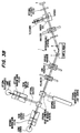
- Figure 3B is similar to 3A but illustrates the use of more than one light source.
- Figure 4A is a simplified diagram of the ellipsometer of Figure 3A illustrating a lens system for focusing, a lens system for refocusing reflected light and a linear detector array for detecting the reflected light from the surface for each of a plurality of different angles of incidence.
- Figure 4B is the simplified ellipsometer of Figure 4A but arranged to detect light transmitted through the sample at each of a plurality of angles.
- Figure 5 is a schematic illustration of a portion of an ellipsometer according to a second embodiment of the invention wherein a wavelength dispersing element is provided along with an area array of detectors for detecting angle of incidence variation at a plurality of wavelengths.
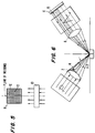
- Figure 6 is a schematic illustration of an ellipsometer of the type shown in Figures 3A and 4A where a portion of the incoming rays to the sample are blocked within a certain, known area to darken a portion of the detector array for properly aligning the sample in preparation for performing the ellipsometry method of the invention.
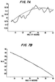
- Figure 7A is a graph of measured values of psi as a function of angle of incidence obtained from a sample using an ellipsometer according to the invention.
- Figure 7B is a graph of measured values of delta as a function of angle of incidence obtained from a sample using an ellipsometer according to the invention.
- the ellipsometer 1 of the invention as shown in Figure 3A comprises means for directing polarized light onto the surface 2 and means for analyzing the polarization state of the light reflected from the surface.
- the means for directing includes a light source, beam shaping optics with an optional optical narrow band filter, a polarizer, a compensator and a variable aperture as in the conventional ellipsometer of Figure 2B.
- the means for directing further includes means for simultaneously directing polarized light from a single beam of light from the light source onto the surface 2 at different angles of incidence. This means for simultaneously directing the light at different angles of incidence onto the surface 2 comprises a focusing lens system 7.
- the lens system 7 has an effective aperture to focal length ratio for focusing the light on the surface 2 with angles of incidence which vary over a range of angles of at least one or two degrees. More particularly, in the illustrated preferred embodiment the range of angles of incidence a is 30 degrees. Larger angles could be employed for directing rays at the sample 2.
- the focusing lens system 7 focuses the polarized light which may be from a He-Ne laser for example, down to a single small spot or point on the surface 2.
- the schematic illustration of Figure 4A depicts several rays A, B, C and D having widely varying angles of incidence which are focused on a single, small spot on the surface 2.
- the light directed on the small spot on surface 2 contains rays at many angles of incidence above and below the angle of incidence of the central ray through the focusing lens.
- Each one of the incoming rays is reflected at an angle equal to its angle of incidence with the polarization state of each of the rays being altered by that reflection, see rays A', B', C' and D' in Figure 4A.
- a detector array 6 is employed to detect a plurality of rays reflected from the surface 2 individually over different, narrow ranges of angles of incidence to simply and quickly obtain data at a plurality of angles of incidence.
- the means for analyzing includes the detector array as well as the analyzer and other elements as shown in Figure 3A and in some embodiments additional lenses represented by lens 8 in the reflected light.
- the diameter d of the lenses 7 and 8 corresponds to their effective diameter.
- the lenses 7 and 8 each have a diameter d of 18mm and a focal length 1 of 34mm.
- Other effective lens diameters and focal lengths could be employed so long as a range of angles of incidence, preferably at least 30°, is provided.
- the lens diameter and focal length are chosen with a view toward maximizing the number of angles of incidence of the light beams which strike the surface 2.
- Figure 4B is similar to Figure 4A but shows an arrangement where light is transmitted through the sample rather than reflected from a surface of the sample.
- the refocusing lens or lenses 8 directs the reflected (transmitted) light toward the detector array 6.
- a refocusing lens need not be employed as the reflected (transmitted) light could be made to directly impinge upon an array of detectors. It is important that the lenses 7 and 8 only negligibly alter the polarization state of the light.
- the detector array 6 is a linear, multiple element detector wherein each of the detector elements 9 can detect a narrow range of angles of incidence of the rays that illuminate the sample.
- the array 6 is a solid-state photosensitive detector array wherein the separate detector elements 9 are all integrated on one circuit chip.
- the detector elements comprise a linear array of photodiodes. While integrated on a single circuit chip, the individual photodiodes can function as separate detectors.
- the linear array of the disclosed embodiment comprises 128 detector elements arranged in a row to provide data for 128 different angles of incidence where the full array is illuminated by the reflected (transmitted) light.
- the number of individual detector elements 9 could be more or less than that in the disclosed embodiment and the detector elements need not be integrated on a single chip but could be discrete detectors.
- the detector elements need not be integrated on a single chip but could be discrete detectors.
- each of the detector elements is less than the expanse of the reflected rays so that each element detects only a certain narrow range of angles of incidence on the illuminating side.
- the output of each of the detectors is used in a conventional manner as with real time computer techniques to generate data in terms of ⁇ and ⁇ for each of those narrow ranges of angles of incidence.
- the data is then interpreted in a conventional manner. It matters in general which direction the linear array runs; the linear array preferably runs in the plane of the optical system.
- the long axis of the linear detector array 6 lies in the plane of incidence of the central ray and perpendicular to the central ray for detecting the maximum number of incidence angles.
- FIG. 5 of the drawings The embodiment of the invention shown in Figure 5 of the drawings is similar to that illustrated in Figures 3A and 4A except that polychromatic light is directed toward the sample rather than monochromatic light.
- a dispersing element 10 is provided in the reflected (or transmitted) beam for dispersing the reflected (transmitted) light from every angle of incidence.
- the detector area array 11 comprises columns of detector elements 12 arranged in linear arrays that are parallel to the plane of incidence of the central ray for detecting variations of angle of incidence. Each column of detector elements 12 sees only a quasimonochromatic portion of the polychromatic light for detecting rays reflected (transmitted) from a plurality of angles of incidence. Additionally, rows of detector elements 13 extend transverse to the plane of incidence of the central ray.
- Each row of detector elements 13 detect the wavelength variation of the dispersed, reflected (transmitted) beam from one of the plurality of angles of incidence.
- a minimum of one row and one column of detectors are required to detect both angle of incidence and wavelength variation. Additional rows and columns of detectors can provide additional useful information.
- the ellipsometer of Figure 5 is advantageous in that it enables simultaneous detection of the beam as a function of angle of incidence and wavelength without scanning either.
- the ellipsometry method of the invention comprises directing polarized light onto a sample surface and analyzing the polarization state of the light reflected from the surface (or transmitted through the sample), wherein polarized light from a single beam of light is simultaneously directed onto the sample at different angles of incidence.
- the light is directed onto the sample surface at a single spot with a cone of polarized light derived from the single beam.
- the angles of incidence preferably vary over a range equal to or greater than 30 degrees but some embodiments may provide as little as 2° of range or a range which is between 2° and 30°.
- Data is gathered for a plurality of different angles of incidence within the range of angles of incidence by detecting the light reflected from the surface (or transmitted through the sample) for each of a plurality of different angles of incidence.
- the detector array can be used to not only simultaneously measure the multiple angles of incidence of the single beam, but can also be used to initially detect whether or not the reflecting surface 2 is in the correct plane relative to the instrument. This is accomplished by eliminating rays within a certain area of the sample of the incoming beam and determining which detector element or elements are dark or not illuminated as a result. Based upon this determination, the operator can change the sample plane as by raising the height of the sample mount 5, for example, until the correct pixel (or pixels) is dark.
- a blocking element 14 obstructs the light from the focusing lens 7 in a certain known area thereby creating a darkened area 15 over a portion of the detector array 6. If the appropriate detector elements are not dark, the operator can correct this by raising or lowering the sample mount so that the sample is in the correct plane or elevation. From the above, it can be seen that the ellipsometer and ellipsometry method of the invention permit the simultaneous illumination of a sample at a whole range of angles of incidence from a single beam of light and collection of a large multiplicity of data for different angles of incidence rapidly and easily and with accuracy.
- the relative angle certainties are more accurate than with conventional mechanical scanning since the relative positions of the detector elements of the detector array are accurately fixed with respect to one another and the ellipsometer during generation of all data. Further, advantageously the actual illuminated spot on the sample area can be extremely small so that all the rays are really measuring nearly the same region of the sample. Therefore, the sample properties can be quickly and accurately computed.
- Figures 7A and 7B show actual ellipsometric data obtained at a plurality of angles of incidence of an instrument designed and constructed according to the preferred embodiment with a range of angles of 10 degrees. These measurements were made on a 1138 Angstrom film of silicon dioxide on a silicon substrate. The solid lines are the measured delta and psi values while the dashed lines represent the theoretical delta and psi computed for this sample.
- the ellipsometer of Figure 3B is like that of Figure 3A except that it has more than one light source, namely an additional, monochromatic light source and also a polychromatic light source as shown in Figure 3B.
- the several light sources are arranged to direct light along a common optical axis of the ellipsometer by way of one or more of mirrors, beam combiners and shutters as depicted in the drawing. Alternatively, the light sources could be selectively energized for providing the light from only one of the sources without need for shutters.
Landscapes
- Physics & Mathematics (AREA)
- General Physics & Mathematics (AREA)
- General Health & Medical Sciences (AREA)
- Chemical & Material Sciences (AREA)
- Analytical Chemistry (AREA)
- Biochemistry (AREA)
- Life Sciences & Earth Sciences (AREA)
- Health & Medical Sciences (AREA)
- Immunology (AREA)
- Pathology (AREA)
- Spectroscopy & Molecular Physics (AREA)
- Investigating Or Analysing Materials By Optical Means (AREA)
- Optical Head (AREA)
- Spectrometry And Color Measurement (AREA)
- Length Measuring Devices By Optical Means (AREA)
Abstract
Description
Claims (42)
- An ellipsometry method comprisingcharacterized in thatdirecting a beam of polarized light at an angle to a normal to the surface of an optical system under study so that said beam interacts with the optical system under study andmeasuring the change in polarization state of the light interacted with the optical system,polarized light from said beam of light is simultaneously directed to interact with the optical system at different angles of incidence to a normal to the surface of the system under study over a range of angles of incidence by focusing the beam of light entirely obliquely on the optical system under study with at least one lens that only negligibly alters the polarization state of the light and with a mean angle of incidence of said focused beam being larger than said range of angles of incidence, andthat the change in polarization state of the light interacted with the optical system under study is measured for each of a plurality of said different angles of incidence.
- An ellipsometry method according to claim 1, wherein the light is interacted with the optical system under study by transmitting it through a material of the optical system.
- An ellipsometry method according to claim 1, wherein the light is interacted with the optical system under study by reflecting it from a surface of the optical system.
- An ellipsometry method according to claim 1, wherein the light is directed onto a surface of the optical system under study at a single spot with a cone of polarized light derived from a single beam.
- An ellipsometry method according to claim 1, wherein the angles of incidence vary over a range of angles of at least 1-2 degrees.
- An ellipsometry method according to claim 1, wherein the range of angles of incidence is from two degrees to more than thirty degrees.
- An ellipsometry method according to claim 1, wherein the light at different angles of incidence is provided by directing parallel light through said at least one lens for focusing the light on the optical system under study, the lens having an effective aperture to focal length ratio for focusing the light on the optical system under study with angles of incidence which vary over a range of at least 1-2 degrees.
- An ellipsometry method according to claim 1, wherein the light directed for interaction with the optical system under study at different angles of incidence is, in general, elliptically polarized light.
- An ellipsometry method according to claim 1, wherein the polarized light is simultaneously directed at different angles of incidence onto the same spot on a surface of the optical system under study for reflection from the surface.
- An ellipsometry method according to claim 9, wherein said spot has a diameter of less than or equal to ten microns.
- An ellipsometry method according to claim 1, wherein the polarized light is monochromatic light.
- An ellipsometry method according to claim 1, wherein the polarized light comprises two or more quasimonochromatic wavelength regions and all but one of the wavelength regions is excluded at a given time.
- An ellipsometry method according to claim 1, wherein said step of measuring includes detecting the light interacted with the optical system under study for each of said plurality of different angles of incidence.
- An ellipsometry method according to claim 13, wherein the interacted light is refocused by passing it through at least one lens before the light is detected.
- An ellipsometry method according to claim 13, wherein the interacted light for each of said plurality of different angles of incident light is separately detected simultaneously.
- An ellipsometry method according to claim 13, wherein a plurality of light detector means are provided in an array located so that respective light detector means intercept and detect interacted light from different angles of incident light.
- An ellipsometry method according to claim 13, further comprising restricting the wavelength regions of the detected light to a quasimonochromatic portion.
- An ellipsometry method according to claim 13, further comprising the steps of dispersing the light interacted with the optical system under study and detecting wavelength variation and angle of incidence variation of the dispersed light.
- An ellipsometry method according to claim 18, wherein the polarized light is polychromatic light.
- An ellipsometry method according to claim 1, including determining a change in amplitude ratio tan ψ and a change in phase difference Δ for light interacted with the optical system under study for each of said plurality of different angles of incidence.
- An ellipsometry method according to claim 1, wherein each of said plurality of different angles of incidence is a narrow range of angles of incidence of the interacted light.
- An ellipsometry method according to claim 1, further including aligning a sample of the optical system under study for ellipsometry, said aligning comprising directing polarized light onto a surface of the sample at different angles of incidence from a single beam of light so that said light is reflected onto a detector array for detecting the light reflected from the surface for each of a plurality of different angles of incidence, and including the steps of eliminating light rays within a certain area of the light beam directed onto the sample surface, determining which area of the detector array is not illuminated by reflected light as a result of said eliminating, and make any necessary adjustments in the position of the sample so that a correct area of the detector is not illuminated by reflected light.
- An ellipsometer comprising means for directing a beam of polarized light at an angle to a normal to the surface of an optical system under study so that said beam interacts with the optical system under study, and means for measuring the change in polarization state of said light interacted with the optical system under study,
characterized in thatsaid means for directing polarized light includes means for simultaneously directing polarized light from said beam of light onto the optical system under study at different angles of incidence to a normal to the surface of the system under study over a range of angles of incidence, that said means for simultaneously directing includes at least one lens for focusing the single beam of light entirely obliquely on the optical system under study while only negligibly altering the polarization state of the light and with a mean angle of incidence of said focused beam being larger than said range of angles of incidence, andthat said means for measuring measures the change in polarization state of light interacted with the optical system under study for each of a plurality of said different angles of incidence. - An ellipsometer according to claim 23, wherein said different angles of incidence vary over a range of at least 1-2 degrees.
- An ellipsometer according to claim 23, wherein the range of angles of incidence is from two degrees to more than thirty degrees.
- An ellipsometer according to claim 23, wherein said at least one lens for focusing the light on the optical system under study having an effective aperture to focal length ratio for focusing the light on the optical system under study with angles of incidence which vary over a range of at least 1-2 degrees.
- An ellipsometer according to claim 23, wherein said means for directing polarized light directs elliptically polarized light onto the optical system under study.
- An ellipsometer according to claim 23, wherein said means for simultaneously directing polarized light onto the optical system under study at different angles of incidence directs the light at different angles of incidence onto the same spot on optical system under study.
- An ellipsometer according to claim 23, wherein said polarized light is monochromatic light.
- An ellipsometer according to claim 23, wherein said means for directing directs polarized light comprising two or more quasimonochromatic wavelength regions, and further comprising means for selectively excluding all but one of the wavelength regions at a time.
- An ellipsometer according to claim 23, wherein said means for measuring includes a plurality of detectors for detecting the light interacted with the optical system under study at each of said plurality of different angles of incidence.
- An ellipsometer according to claim 31, said means for measuring further comprising a lens or lenses for refocusing the interacted light before it is detected by said plurality of detectors.
- An ellipsometer according to claim 31, wherein said plurality of detectors is in the form of an array of light detectors located so that respective light detectors intercept and detect interacted light from said different angles of incident light.
- An ellipsometer according to claim 33, wherein said array is a linear array of light detectors.
- An ellipsometer according to claim 33, wherein said detectors are solid-state photosensitive detectors which are integrated on a semiconductor chip.
- An ellipsometer according to claim 23, further comprising means for dispersing the interacted light and means for detecting wavelength variation together with angle of incidence variation of the dispersed light.
- An ellipsometer according to claim 36, wherein the polarized light is polychromatic light.
- An ellipsometer according to claim 23, wherein the means for directing polarized light comprises a plurality of light sources each arranged to provide light which travels along a common optical axis.
- An ellipsometer according to claim 38, further comprising means for preventing the polarized light from one or more of the plurality of sources from reaching the means for measuring.
- An ellipsometer according to claim 39, wherein said means for preventing is one of the group consisting of a shutter, a means for de-energizing said one or more light sources and a blocking filter.
- An ellipsometer according to claim 23, wherein said means for measuring enables determination of a change in amplitude ratio tan ψ and a change in phase difference Δ for light interacted with the optical system under study for each of said plurality of different angles of incidence.
- An ellipsometer according to claim 23, wherein each of said plurality of different angles of incidence is a narrow range of angles of incidence of the interacted light.
Applications Claiming Priority (3)
| Application Number | Priority Date | Filing Date | Title |
|---|---|---|---|
| US64010091A | 1991-01-11 | 1991-01-11 | |
| US640100 | 1991-01-11 | ||
| PCT/US1992/000280 WO1992012404A1 (en) | 1991-01-11 | 1992-01-10 | Simultaneous multiple angle/multiple wavelength ellipsometer and method |
Publications (3)
| Publication Number | Publication Date |
|---|---|
| EP0566657A1 EP0566657A1 (en) | 1993-10-27 |
| EP0566657A4 EP0566657A4 (en) | 1994-04-13 |
| EP0566657B1 true EP0566657B1 (en) | 1998-08-05 |
Family
ID=24566845
Family Applications (1)
| Application Number | Title | Priority Date | Filing Date |
|---|---|---|---|
| EP92904023A Expired - Lifetime EP0566657B1 (en) | 1991-01-11 | 1992-01-10 | Simultaneous multiple angle/multiple wavelength ellipsometer and method |
Country Status (7)
| Country | Link |
|---|---|
| EP (1) | EP0566657B1 (en) |
| JP (1) | JP3360822B2 (en) |
| KR (1) | KR100203345B1 (en) |
| AT (1) | ATE169400T1 (en) |
| CA (1) | CA2099491A1 (en) |
| DE (1) | DE69226514T2 (en) |
| WO (1) | WO1992012404A1 (en) |
Families Citing this family (21)
| Publication number | Priority date | Publication date | Assignee | Title |
|---|---|---|---|---|
| IL104708A (en) * | 1993-02-12 | 1995-12-31 | Orbotech Ltd | Apparatus and method for optical inspection of articles |
| US5408322A (en) * | 1993-04-26 | 1995-04-18 | Materials Research Corporation | Self aligning in-situ ellipsometer and method of using for process monitoring |
| US5412473A (en) * | 1993-07-16 | 1995-05-02 | Therma-Wave, Inc. | Multiple angle spectroscopic analyzer utilizing interferometric and ellipsometric devices |
| US7215424B1 (en) | 1998-03-03 | 2007-05-08 | J.A. Woollam Co., Inc. | Broadband ellipsometer or polarimeter system including at least one multiple element lens |
| US7518725B1 (en) | 1995-09-20 | 2009-04-14 | J.A. Woollam Co., Inc. | Temperature controlled lens |
| US5742392A (en) * | 1996-04-16 | 1998-04-21 | Seymour Light, Inc. | Polarized material inspection apparatus |
| DE19707926A1 (en) * | 1997-02-27 | 1998-09-03 | Gunther Dr Elender | Imaging micro ellipsometer |
| US5979244A (en) * | 1998-03-04 | 1999-11-09 | Siemens Aktiengesellschaft | Method and apparatus for evaluating internal film stress at high lateral resolution |
| DE19943312A1 (en) * | 1999-09-10 | 2001-03-15 | Haverkamp Mark | Procedure and device for on-line thickness measurement of transparent layers or media using transmission ellipsometry, which yields much more accurate results for transparent media than reflection ellipsometry |
| JP3447654B2 (en) * | 2000-03-24 | 2003-09-16 | Necエレクトロニクス株式会社 | Anisotropic thin film evaluation method and evaluation device |
| DE10021378A1 (en) * | 2000-05-02 | 2001-11-08 | Leica Microsystems | Optical measuring arrangement with an ellipsometer |
| FR2809491B1 (en) * | 2000-05-26 | 2008-07-04 | Production Rech S Appliquees | METHOD AND APPARATUS FOR ELLIPSOMETRIC METROLOGY FOR SAMPLE CONTAINED IN A CHAMBER OR THE LIKE |
| US6750968B2 (en) | 2000-10-03 | 2004-06-15 | Accent Optical Technologies, Inc. | Differential numerical aperture methods and device |
| JP4399126B2 (en) | 2001-04-25 | 2010-01-13 | 株式会社堀場製作所 | Spectroscopic ellipsometer |
| DE10303940A1 (en) * | 2003-01-31 | 2004-08-19 | Siemens Ag | Normalization of medical X-ray diagnostic images by storage of a set of processed compressed image data obtained without an object and use of the stored data to normalize actual object radiographic data sets |
| US7446882B2 (en) * | 2005-01-20 | 2008-11-04 | Zygo Corporation | Interferometer for determining characteristics of an object surface |
| US9903711B2 (en) * | 2015-04-06 | 2018-02-27 | KLA—Tencor Corporation | Feed forward of metrology data in a metrology system |
| CN110132420B (en) * | 2018-02-09 | 2020-11-27 | 上海微电子装备(集团)股份有限公司 | Polarization measurement device, polarization measurement method, and optical alignment method |
| JP7226243B2 (en) * | 2019-10-29 | 2023-02-21 | 横河電機株式会社 | Fourier spectrometer |
| CN111624159B (en) * | 2020-07-02 | 2025-01-28 | 北京量拓科技有限公司 | Ellipsometry measurement device and measurement method |
| CN113985592B (en) * | 2021-09-24 | 2024-09-03 | 江苏锐精光电研究院有限公司 | Multi-angle total internal reflection illumination imaging device based on dispersion element |
Citations (2)
| Publication number | Priority date | Publication date | Assignee | Title |
|---|---|---|---|---|
| US4472633A (en) * | 1981-02-09 | 1984-09-18 | Hitachi, Ltd. | Method and apparatus of measuring carrier distribution |
| EP0396409A2 (en) * | 1989-05-04 | 1990-11-07 | THERMA-WAVE, INC. (a Delaware corporation) | High resolution ellipsometric apparatus |
Family Cites Families (6)
| Publication number | Priority date | Publication date | Assignee | Title |
|---|---|---|---|---|
| US4434025A (en) * | 1981-06-04 | 1984-02-28 | Robillard Jean J | Controlling crystallinity and thickness of monocrystalline layer by use of an elliptically polarized beam of light |
| DE3339970A1 (en) * | 1983-11-04 | 1985-05-15 | Karl Süss KG, Präzisionsgeräte für Wissenschaft und Industrie GmbH & Co, 8046 Garching | DEVICE FOR AUTOMATIC FOCUSING OF OPTICAL DEVICES |
| US4672196A (en) * | 1984-02-02 | 1987-06-09 | Canino Lawrence S | Method and apparatus for measuring properties of thin materials using polarized light |
| US4838695A (en) * | 1987-06-12 | 1989-06-13 | Boston University | Apparatus for measuring reflectivity |
| US4957368A (en) * | 1989-03-16 | 1990-09-18 | Photoacoustic Technology, Inc. | Apparatus and process for performing ellipsometric measurements of surfaces |
| US4999014A (en) * | 1989-05-04 | 1991-03-12 | Therma-Wave, Inc. | Method and apparatus for measuring thickness of thin films |
-
1992
- 1992-01-10 WO PCT/US1992/000280 patent/WO1992012404A1/en not_active Ceased
- 1992-01-10 DE DE69226514T patent/DE69226514T2/en not_active Expired - Fee Related
- 1992-01-10 EP EP92904023A patent/EP0566657B1/en not_active Expired - Lifetime
- 1992-01-10 CA CA002099491A patent/CA2099491A1/en not_active Abandoned
- 1992-01-10 JP JP50454292A patent/JP3360822B2/en not_active Expired - Lifetime
- 1992-01-10 KR KR1019930702082A patent/KR100203345B1/en not_active Expired - Lifetime
- 1992-01-10 AT AT92904023T patent/ATE169400T1/en not_active IP Right Cessation
Patent Citations (2)
| Publication number | Priority date | Publication date | Assignee | Title |
|---|---|---|---|---|
| US4472633A (en) * | 1981-02-09 | 1984-09-18 | Hitachi, Ltd. | Method and apparatus of measuring carrier distribution |
| EP0396409A2 (en) * | 1989-05-04 | 1990-11-07 | THERMA-WAVE, INC. (a Delaware corporation) | High resolution ellipsometric apparatus |
Also Published As
| Publication number | Publication date |
|---|---|
| EP0566657A1 (en) | 1993-10-27 |
| WO1992012404A1 (en) | 1992-07-23 |
| DE69226514T2 (en) | 1999-04-08 |
| ATE169400T1 (en) | 1998-08-15 |
| EP0566657A4 (en) | 1994-04-13 |
| JPH06504845A (en) | 1994-06-02 |
| KR100203345B1 (en) | 1999-06-15 |
| JP3360822B2 (en) | 2003-01-07 |
| DE69226514D1 (en) | 1998-09-10 |
| KR930703594A (en) | 1993-11-30 |
| CA2099491A1 (en) | 1992-07-12 |
Similar Documents
| Publication | Publication Date | Title |
|---|---|---|
| US5166752A (en) | Simultaneous multiple angle/multiple wavelength ellipsometer and method | |
| EP0566657A4 (en) | ||
| US5042951A (en) | High resolution ellipsometric apparatus | |
| US5581350A (en) | Method and system for calibrating an ellipsometer | |
| KR100484377B1 (en) | Spectroscopic ellipsometer | |
| US7616319B1 (en) | Spectroscopic ellipsometer and polarimeter systems | |
| US6750968B2 (en) | Differential numerical aperture methods and device | |
| US7633625B1 (en) | Spectroscopic ellipsometer and polarimeter systems | |
| US6256097B1 (en) | Ellipsometer and ellipsometry method | |
| US5754296A (en) | Ellipsometric microscope | |
| US5764365A (en) | Two-dimensional beam deflector | |
| US5910842A (en) | Focused beam spectroscopic ellipsometry method and system | |
| EP1026495B1 (en) | Adjustable beam alignment compensator/retarder | |
| EP0396409B1 (en) | High resolution ellipsometric apparatus | |
| EP0397388A2 (en) | Method and apparatus for measuring thickness of thin films | |
| KR20190118603A (en) | Systems and Methods for Use in Ellipsometry with High Spatial Resolution | |
| US20230266233A1 (en) | System for measuring thickness and physical properties of thin film using spatial light modulator | |
| US7245376B2 (en) | Combined spatial filter and relay systems in rotating compensator ellipsometer/polarimeter | |
| US7206070B2 (en) | Beam profile ellipsometer with rotating compensator | |
| EP1212580B1 (en) | Method and apparatus for performing optical measurements of layers and surface properties | |
| USRE38153E1 (en) | Two-dimensional beam deflector | |
| US7336361B1 (en) | Spectroscopic ellipsometer and polarimeter systems | |
| US6784991B2 (en) | Diffractive optical elements and grid polarizers in focusing spectroscopic ellipsometers | |
| US11668645B2 (en) | Spectroscopic ellipsometry system for thin film imaging | |
| WO1996024034A1 (en) | Method for improving optical measurement of rough samples in ellipsometry and reflectometry |
Legal Events
| Date | Code | Title | Description |
|---|---|---|---|
| PUAI | Public reference made under article 153(3) epc to a published international application that has entered the european phase |
Free format text: ORIGINAL CODE: 0009012 |
|
| 17P | Request for examination filed |
Effective date: 19930703 |
|
| AK | Designated contracting states |
Kind code of ref document: A1 Designated state(s): AT BE CH DE DK ES FR GB GR IT LI LU MC NL SE |
|
| A4 | Supplementary search report drawn up and despatched |
Effective date: 19940224 |
|
| AK | Designated contracting states |
Kind code of ref document: A4 Designated state(s): AT BE CH DE DK ES FR GB GR IT LI LU MC NL SE |
|
| 17Q | First examination report despatched |
Effective date: 19950508 |
|
| GRAG | Despatch of communication of intention to grant |
Free format text: ORIGINAL CODE: EPIDOS AGRA |
|
| GRAG | Despatch of communication of intention to grant |
Free format text: ORIGINAL CODE: EPIDOS AGRA |
|
| GRAH | Despatch of communication of intention to grant a patent |
Free format text: ORIGINAL CODE: EPIDOS IGRA |
|
| GRAH | Despatch of communication of intention to grant a patent |
Free format text: ORIGINAL CODE: EPIDOS IGRA |
|
| GRAA | (expected) grant |
Free format text: ORIGINAL CODE: 0009210 |
|
| AK | Designated contracting states |
Kind code of ref document: B1 Designated state(s): AT BE CH DE DK ES FR GB GR IT LI LU MC NL SE |
|
| PG25 | Lapsed in a contracting state [announced via postgrant information from national office to epo] |
Ref country code: NL Free format text: LAPSE BECAUSE OF FAILURE TO SUBMIT A TRANSLATION OF THE DESCRIPTION OR TO PAY THE FEE WITHIN THE PRESCRIBED TIME-LIMIT Effective date: 19980805 Ref country code: LI Free format text: LAPSE BECAUSE OF FAILURE TO SUBMIT A TRANSLATION OF THE DESCRIPTION OR TO PAY THE FEE WITHIN THE PRESCRIBED TIME-LIMIT Effective date: 19980805 Ref country code: IT Free format text: LAPSE BECAUSE OF FAILURE TO SUBMIT A TRANSLATION OF THE DESCRIPTION OR TO PAY THE FEE WITHIN THE PRE;WARNING: LAPSES OF ITALIAN PATENTS WITH EFFECTIVE DATE BEFORE 2007 MAY HAVE OCCURRED AT ANY TIME BEFORE 2007. THE CORRECT EFFECTIVE DATE MAY BE DIFFERENT FROM THE ONE RECORDED.SCRIBED TIME-LIMIT Effective date: 19980805 Ref country code: GR Free format text: LAPSE BECAUSE OF NON-PAYMENT OF DUE FEES Effective date: 19980805 Ref country code: ES Free format text: THE PATENT HAS BEEN ANNULLED BY A DECISION OF A NATIONAL AUTHORITY Effective date: 19980805 Ref country code: CH Free format text: LAPSE BECAUSE OF FAILURE TO SUBMIT A TRANSLATION OF THE DESCRIPTION OR TO PAY THE FEE WITHIN THE PRESCRIBED TIME-LIMIT Effective date: 19980805 Ref country code: BE Free format text: LAPSE BECAUSE OF FAILURE TO SUBMIT A TRANSLATION OF THE DESCRIPTION OR TO PAY THE FEE WITHIN THE PRESCRIBED TIME-LIMIT Effective date: 19980805 Ref country code: AT Free format text: LAPSE BECAUSE OF FAILURE TO SUBMIT A TRANSLATION OF THE DESCRIPTION OR TO PAY THE FEE WITHIN THE PRESCRIBED TIME-LIMIT Effective date: 19980805 |
|
| REF | Corresponds to: |
Ref document number: 169400 Country of ref document: AT Date of ref document: 19980815 Kind code of ref document: T |
|
| REG | Reference to a national code |
Ref country code: CH Ref legal event code: EP |
|
| REF | Corresponds to: |
Ref document number: 69226514 Country of ref document: DE Date of ref document: 19980910 |
|
| PG25 | Lapsed in a contracting state [announced via postgrant information from national office to epo] |
Ref country code: SE Free format text: LAPSE BECAUSE OF FAILURE TO SUBMIT A TRANSLATION OF THE DESCRIPTION OR TO PAY THE FEE WITHIN THE PRESCRIBED TIME-LIMIT Effective date: 19981105 Ref country code: DK Free format text: LAPSE BECAUSE OF FAILURE TO SUBMIT A TRANSLATION OF THE DESCRIPTION OR TO PAY THE FEE WITHIN THE PRESCRIBED TIME-LIMIT Effective date: 19981105 |
|
| ET | Fr: translation filed | ||
| NLV1 | Nl: lapsed or annulled due to failure to fulfill the requirements of art. 29p and 29m of the patents act | ||
| PG25 | Lapsed in a contracting state [announced via postgrant information from national office to epo] |
Ref country code: LU Free format text: LAPSE BECAUSE OF NON-PAYMENT OF DUE FEES Effective date: 19990110 |
|
| REG | Reference to a national code |
Ref country code: CH Ref legal event code: PL |
|
| PLBE | No opposition filed within time limit |
Free format text: ORIGINAL CODE: 0009261 |
|
| STAA | Information on the status of an ep patent application or granted ep patent |
Free format text: STATUS: NO OPPOSITION FILED WITHIN TIME LIMIT |
|
| 26N | No opposition filed | ||
| PG25 | Lapsed in a contracting state [announced via postgrant information from national office to epo] |
Ref country code: MC Free format text: LAPSE BECAUSE OF NON-PAYMENT OF DUE FEES Effective date: 19990731 |
|
| REG | Reference to a national code |
Ref country code: GB Ref legal event code: IF02 |
|
| REG | Reference to a national code |
Ref country code: FR Ref legal event code: CD |
|
| PGFP | Annual fee paid to national office [announced via postgrant information from national office to epo] |
Ref country code: GB Payment date: 20071224 Year of fee payment: 17 |
|
| PGFP | Annual fee paid to national office [announced via postgrant information from national office to epo] |
Ref country code: DE Payment date: 20080116 Year of fee payment: 17 |
|
| GBPC | Gb: european patent ceased through non-payment of renewal fee |
Effective date: 20090110 |
|
| PG25 | Lapsed in a contracting state [announced via postgrant information from national office to epo] |
Ref country code: DE Free format text: LAPSE BECAUSE OF NON-PAYMENT OF DUE FEES Effective date: 20090801 |
|
| PG25 | Lapsed in a contracting state [announced via postgrant information from national office to epo] |
Ref country code: GB Free format text: LAPSE BECAUSE OF NON-PAYMENT OF DUE FEES Effective date: 20090110 |
|
| PGFP | Annual fee paid to national office [announced via postgrant information from national office to epo] |
Ref country code: FR Payment date: 20110301 Year of fee payment: 20 |