EP0565681B1 - Control of power network - Google Patents
Control of power network Download PDFInfo
- Publication number
- EP0565681B1 EP0565681B1 EP92922592A EP92922592A EP0565681B1 EP 0565681 B1 EP0565681 B1 EP 0565681B1 EP 92922592 A EP92922592 A EP 92922592A EP 92922592 A EP92922592 A EP 92922592A EP 0565681 B1 EP0565681 B1 EP 0565681B1
- Authority
- EP
- European Patent Office
- Prior art keywords
- voltage
- current
- mode
- power network
- pole
- Prior art date
- Legal status (The legal status is an assumption and is not a legal conclusion. Google has not performed a legal analysis and makes no representation as to the accuracy of the status listed.)
- Expired - Lifetime
Links
Images


Classifications
-
- H—ELECTRICITY
- H02—GENERATION; CONVERSION OR DISTRIBUTION OF ELECTRIC POWER
- H02J—ELECTRIC POWER NETWORKS; CIRCUIT ARRANGEMENTS OR SYSTEMS FOR SUPPLYING OR DISTRIBUTING ELECTRIC POWER; SYSTEMS FOR STORING ELECTRIC ENERGY
- H02J3/00—Circuit arrangements for AC mains or AC distribution networks
- H02J3/01—Arrangements for reducing harmonics or ripples
-
- Y—GENERAL TAGGING OF NEW TECHNOLOGICAL DEVELOPMENTS; GENERAL TAGGING OF CROSS-SECTIONAL TECHNOLOGIES SPANNING OVER SEVERAL SECTIONS OF THE IPC; TECHNICAL SUBJECTS COVERED BY FORMER USPC CROSS-REFERENCE ART COLLECTIONS [XRACs] AND DIGESTS
- Y02—TECHNOLOGIES OR APPLICATIONS FOR MITIGATION OR ADAPTATION AGAINST CLIMATE CHANGE
- Y02E—REDUCTION OF GREENHOUSE GAS [GHG] EMISSIONS, RELATED TO ENERGY GENERATION, TRANSMISSION OR DISTRIBUTION
- Y02E40/00—Technologies for an efficient electrical power generation, transmission or distribution
- Y02E40/40—Arrangements for reducing harmonics
Definitions
- the present invention relates to a method, and to a device for carrying out the method, for control of at least one of a first and a second power network, which are interconnected by means of at least two conductors, for the purpose of controlling, according to a predetermined criterion, the influence by one of the networks on the other network.
- the first power network comprises at least one current or voltage generator with associated internal impedance and at least one of the first and the second power networks comprises at least one controllable network element.
- the device comprises a control member which, based on a direction-dependent signal processing, generates control signals for control of controllable network elements arranged in the power network.
- the principal drawback in this case is that both delay effects and other non-minimum phase properties and other kinds of dynamic properties are not taken into consideration and compensated for.
- the correction of the memory contents with the system deviation delayed one cycle may render the controller unstable since in reality both implicit and explicit delay effects may occur in addition to other kinds of dynamic properties.
- the total delay in the system may amount to more than one cycle and even if the controlled system is stable, the attenuation of disturbances, repeated once every cycle, will not be good.
- the invention aims to provide a method of the kind described in the introductory part of the description, which particularly in those cases where one of the power networks makes difficult a control by exhibiting complicated, varying or otherwise limiting dynamic properties for control in general, caused by, for example, switchings or by non-minimum phase properties, permits a rapid and stable control, as well as a device for carrying out the method.
- the above is achieved by making the control independent of that power network which entails the above-mentioned difficulties in that actual values for controllers included in the device are formed in dependence on at least one current measurement and at least one voltage measurement in a section between the power networks, as well as a direction-dependent signal processing of these measured values according to the invention.
- the above-mentioned section is defined such that current and/or voltage generators, which are to be controlled such that their influence on currents and/or voltages occurring in the section or in that power network which causes the above-mentioned difficulties arising in connection with the control, are located in one of the power networks, hereafter called the first power network, and those parts of the power networks which give rise to the above-mentioned difficulties arising in connection with the control are located in the other power network, hereafter called the second power network.
- the direction-dependent signal processing the actual values will become independent of disturbance and impedance conditions in the second power network.
- this power network cannot entail stability problems, and in the case of feedback control, other control performance properties are also not influenced by this power network. Disturbances originating from the second power network are not included in the actual values and cannot, therefore, be cancelled. These circumstances indicate that the actual values are direction-dependent.
- feedback control can be achieved only if the controllable network elements are located in the first power network, and the parameter setting of the controllers as well as the distribution of control action to any additional controllable network elements become dependent only on this power network.
- the invention can be used generally in power networks to isolate different types of interference, originating from controllers, in different parts of a power network from each other. In this way, the control systems for these different parts can be designed independently of each other.
- the actual values can be utilized to reduce the influence of non-minimum phase properties in the transfer function of the network but also to reduce the influence from those parts of the network whose dynamic properties are changing in time, for example by switchings, or otherwise have complicated dynamics.
- it is important to reduce the influence from the dynamics of output power lines, which exhibit both delay effects and dynamics variable in time.
- a feed-forward control or open-loop control is obtained if the controllable network elements are located in the second power network. In this case, no feedback is obtained to the controllers via the actual values as a result of control interference. This means that instability cannot arise caused by feedback.
- the actual values can be utilized as input quantities for calculations in calculating models.
- the multiple measurements of current and voltage can also be utilized to reconstruct, by calculations, stiff voltage sources for the purpose of avoiding non-desirable feedbacks, that is, effects through the feed-forward control of the power network by feedback via the current and voltage measurements on which the feed-forward control is based.
- the actual values can be utilized to control specific disturbance modes in a power network.
- An example of such an application is cancellation of electrical disturbances which propagate as an electromagnetic wave in space between, on the one hand, a power line consisting of a number of electric conductors viewed as one unit and, on the other hand, ground along the power line.
- the device for forming actual values comprises an implicit or explicit model of the first power network but contains no information about the second power network.
- One criterion for the control may, for example, be to reduce disturbances such as harmonic currents or harmonic voltages, generated by a disturbance source included in one of the power networks or connected thereto, which disturbances are transferred to the other power network.
- one of the power networks may be part of a plant for transmission of high-voltage direct current and comprise a convertor, generating harmonic voltages or harmonic currents which are transmitted to the other power network via d.c. or a.c. lines.
- Other fields of application of the invention are, for example, cases where one of the networks constitutes at least part of a power supply for electric drive systems and comprises convertors or other commutating circuits, generating harmonic currents and/or voltages which are transmitted to a supply power network.
- Such a power network may, for example, be part of a drive system for electric traction.
- Still other fields of application are, for example, such where one of the power networks comprises an electric generator for power generation.
- the following description relates to the method as well as to the device.
- Figure 1 shows a first power network 1, which by means of L electric conductors 2, where L is greater than or equal to 2, is connected to a second power network 3.
- the first power network comprises at least one controllable network element 4 and at least one current and/or voltage generator 5 with an internal impedance associated with the generator.
- a network element 4 may, for example, consist of an active filter, generating a voltage or current which is supplied to the first power network, or of a controllable impedance in the first power network.
- only one of the conductors 2 and only one network element 4 and only one current and/or voltage generator 5 are provided with reference numerals, but it is to be understood that configurations similar to the designated ones are to symbolize elements of the same kind.
- At least one of the network elements is supplied with a control signal C(r), generated by a control member 6, the voltage or current generated by the network element, or the impedance it exhibits, being dependent on the supplied control signal.
- the current and/or voltage generators 5 may, for example, consist of a convertor but also of a disturbance inductively or capacitively coupled to the first power network, which disturbance will then be regarded as a disturbance current or disturbance voltage generator provided in the network. It is assumed for the first power network that the principle of superposition can be applied for summation of the currents and voltages, respectively, which are generated in the power network as a result of interference from the network elements, at least around the working point at which the power network is situated prior to such interference.
- the impedances and current and/or voltage sources of the second power network may be unknown and/or variable, for example as a result of switchings made within the second power network. Dashed lines and configurations in Figure 1 designate that the number of these may be greater or smaller than the shown. To the extent that the number has to be stated in the following, it is assumed that the number of controllable network elements amounts to NC such elements and the number of current and/or voltage generators amounts to NG such generators.
- a section B-B is conceived to intersect the conductors 2 such that the first and second power networks will be located on different sides of the section, and in the section there are sensed in a manner known per se, by means of a measuring device 7, at least one line current IL(k) flowing through the section in any of the conductors, and at least one voltage occurring at the section.
- the voltages may thereby be sensed and the measuring device be arranged in a way, known per se, such that the measuring device forms either a value of the voltage V(j) of the respective conductor, relative to a common reference level, at a selected conductor, whereby the voltage V(j) will hereafter be called a node voltage, or alternatively forms voltage differences E(n) between conductors two by two, whereby a voltage difference E(n) will hereafter be called a driving voltage.
- the measuring device may also comprise members, arranged in a manner known per se, for suppression of certain predetermined frequency components in the sensed currents and/or voltages, including members for elimination of d.c. components in the sensed values. Via the measuring device 7 the control member 6 is supplied with values of at least one line current IL(k) and at least one node voltage V(j) or driving voltage E(n).
- each such mesh current may be calculated as a sum of contributions from each one of the current and voltage generators located in the networks, whereby when calculating the contribution of each current and voltage generator, all the other voltage generators are conceived to be short-circuited and all the other current generators are conceived to be disconnected from the networks and replaced by their internal impedances.
- current and voltage generators in both the first power network 1 and the second power network 2 contribute to the mesh currents IC(p).
- the contribution of the second network is thereby conceived, as marked in the figure, to be expresed as the voltages E(n) driving the mesh currents.
- the p'th mesh current IC(p) consists of a contribution ICN1(p) from the first power network 1 and a contribution ICN2(p) which is dependent on the second power network 2 as well as the connection of this to the first power network 1 in section B-B.
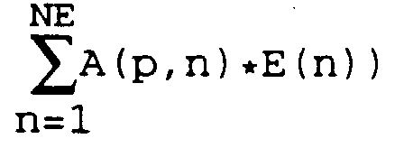
- A(p,n) is a transfer function with the dimension admittance which expresses the dependence of the p'th mesh current IC(p) on the n'th driving voltage E(n).
- the driving voltages E(n) it can be said in an analogous manner that the n'th driving voltage E(n) consists of a contribution ENl(n) from the first power network 1 and a contribution EN2(n) which depends on the second power network 2 as well as the connection of this to the first power network 1 in section B-B.
- This can be expressed, by way of equation, as follows: where formally the running index n has been replaced by a running index p and where B(p,m) is a transfer function with the dimension impedance which expresses the dependence of the p'th driving voltage E(p) on the m'th mesh current IC(m).
- the k'th line current IL(k) consists of a contribution ILN1(k) from the first power network 1 and a contribution ILN2(k) which depends on the second power network 2 as well as the connection thereof to the first power network 1 in section B-B.
- This can be expressed, by way of equation, as follows: where formally the running index k is replaced by the running index p and where F(p,j) is a transfer function with the dimension admittance which expresses the dependence of the p'th line current IL(p) on the j'th node voltage V(j).
- the j'th node voltage V(j) consists of a contribution VN1(j) from the first power network 1 and a contribution VN2(j) which depends on the second power network 2 as well as the connection thereof to the first power network 1 in section B-B.
- This can be expressed, by way of equation, as follows: where formally the running index n is replaced by the running index p and where G(p,k) is a transfer function with the dimension impedance which expresses the dependence of the p'th node voltage V(p) on the k'th line current IL(k).
- a linear combination of a number of variables there is meant in the following a sum of terms, each term being formed as the product of a variable, multiplied by a weight factor associated with the variable.
- the weight factor may be a real number but also, for example, a frequency-dependent transfer function.
- the variables may be expressed in vector form and the weight factors form a matrix, in which case also the linear combination will be expressed in vector form.
- the contributions ICN2(p), ILN2(k), EN2(n) and VN2(j) thus consist of linear combinations of voltages E(n) and V(j), respectively, and currents IC(m) and IL(k), respectively, weighted with admittance functions A(p,n) and F(p,j), respectively, and impedance functions B(p,m) and G(p,k), respectively.
- the mesh currents IC(m) can be expressed as linear combinations of measured line currents IL(k), which in equation form may be expressed as follows: where KI(m,k) designates the coefficients by which line currents are weighed together in the combination referred to, or with other running indexes
- KI(m,k) designates the coefficients by which line currents are weighed together in the combination referred to, or with other running indexes
- BM(p) a variable BM(p), hereafter called base mode, which depends on at least one sensed current and at least one sensed voltage, the base mode being independent of the impedance functions of the second power network 2, of disturbance voltages and/or disturbance currents generated in the second power network and of changes in the dynamic properties thereof, caused by, for example, switchings in the second power network.
- the base mode BM(p) is set equal to the contribution ICN1(p) from the first power network 1 to the p'th mesh current IC(p) according to equation (1a), or equal to the contribution EN1(p) from the first power network 1 to the p'th driving voltage E(p) according to equation (1b), or equal to the contribution INL1(p) from the first power network 1 to the p'th line current IL(p) according to 1c) or equal to the contribution VN1(p) from the first power network 1 to the p'th node voltage V(p) according to equation (1d).
- the control member 6 is supplied with the values, formed in the measuring device 7, of the line currents IL(k) and the driving voltages E(n) or node voltages V(j).
- the line currents IL(k) are supplied to a current combination unit 61, comprised in the control member and shown in Figures 2a and 3, which in a manner known per se performs the linear combination which is expressed in equations (2) and (2a).
- the mesh currents IC(m) and the driving voltages E(n) or, alternatively, the line currents IL(k) and the node voltages V(j) are supplied to a base mode filter 62 comprised in the control member and shown in Figures 2a and 4.
- the base mode filter according to Figure 4 comprises current filters 621, the transfer function of which is designated BMFI(p,m), voltage filters 622, the transfer function of which is designated BMFE(p,n), current summators 623, voltage summators 624 and base mode summators 625, and forms, as is clear from Figures 2a and 4, of the supplied values I(m) and U(n) one or more linear combinations BM(p) and its function can be expressed in equation form as where I(m) has been introduced as a common designation for the mesh current IC(m) or, alternatively, the line current IL(k) and U(n) as a common designation for the driving voltage E(n) or, alternatively, the node voltage V(j).
- the number NI of the currents I(m) is equal to the respective NIC or NIL and the number NU of the voltages U(n) is equal to the respective NE or NV.
- the current and voltage summators have been introduced to clarify the function of the device but they may, of course, as is clear from the figure, be excluded, in which case the current and voltage filters are connected directly to the respective base mode summators.
- a set of state variables Y(i) comprising either a full set of mesh currents IC(m) and driving voltages E(n) or, alternatively, a full set of line currents IL(k) and node voltages V(j), and which is supplied to the base mode filter, unambiguously define the state in the section B-B.
- state variables Y(i) in section B-B are to be controlled, there is no requirement for an unambiguous determination of all the state variables. Such incomplete state determinations will be defined and described below in connection with the introduction of the concept mode. In such cases, there is no requirement for measurement of a full set of mesh currents IC(m) and driving voltages E(n), or a full set of line currents IL(k) and node voltages V(j).
- the above-mentioned object of the invention is thus achieved by selecting the transfer functions BMFI(p,m) and BMFE(p,n) for the current filters 621 and the voltage filters 622, respectively, in the base mode filter in accordance with equations (5a)...(5d) and (6a)...(6d) above, in that the equations (3a)...(3d) and the assumptions for these are thereby fulfilled.
- Equation (4) expressed for the case where the base mode BM(p) is set equal to the contribution ICN1(p) from the first power network 1 to the p'th mesh current IC(p) according to equations (1a) and (3a), is then obtained with equations (5a) and (6a) inserted and with IC(p) according to equation (2a) where the line currents IL(k) and the driving voltages E(n) are thus supplied to the base mode filter from the measuring device 7.
- the base mode BM(p) can be regarded as a current.
- the base mode BM(p) can be regarded as a voltage.
- Figures 11a-11d schematically show how the base mode BM(p) is formed according to equations (8a), (8b), (7c) and (7d) and with the relationships (5a)...(5d) and (6a)...(6d) inserted, respectively.
- the base mode filter as shown in Figure 4 thus constitutes an implementation of the general assumption according to equation (4) but as is clear from the expressions (5a)...(5d) and (6a)...(6d), the transfer functions for certain current and voltage filters assume the value one or zero, the value zero indicating that the filter in question can be excluded.
- Another object of the invention is now to form from the base modes BM(p) a variable M(q), hereafter called mode, for the purpose of selecting certain currents and voltages for control of the first power network in such a way that the influence of the first power network on these currents and voltages fulfils certain predetermined criteria for its influence on the second power network.
- the base modes BM(p) are supplied to a mode generator 63, comprised in the control member and shown in Figures 2a, 2b and 6a, 6b.
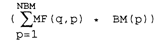
- the mode generator comprises mode filters 631, the transfer functions of which are designated MF(q,p), and mode summators 632 for summing up the base modes from which a mode is to be formed.
- the mode generator forms from the base modes BM(p) one or more linear combinations M(q) and its function can be expressed in equation form as
- the mode M(q) is dependent on contributions from the first power network 1 and on the filter functions which are introduced independently of the second power network. This results in also the mode M(q) being independent of impedance functions, dynamic system properties, switchings and of disturbances associated with the second power network 2. All information about these facts is filtered out in the base mode filter by the current filters 621 and the voltage filters 622, which have the transfer functions included in the righthand term of equations (7a)...(7d).
- a controller which is supplied with the mode M(q) as actual value for comparison with a desired value RM(q) of the mode M(q), and whose output signal controls one or more network elements in the first power network 1, will thus not be influenced by the second power network 2.
- the control becomes direction-dependent from the first power network 1 towards the section B-B, and disturbances generated by the second power network 3 and which occur in section B-B will not be considered since they are filtered out when forming the base modes.
- each one of the modes M(q) being supplied to a controller, comprised in the control member and belonging to the respective mode, shown in Figures 2a and 6a.
- a controller comprised in the control member and belonging to the respective mode, shown in Figures 2a and 6a.
- all the controllers have been marked with the reference numeral 64, although it is to be understood that in this embodiment each mode to be controlled is associated with its own controller.
- the mode M(q) is compared with a desired reference value RM(q) for the respective mode.
- the controller in some way, for example in dependence on the deviation between the value of the mode and its reference value, the controller generates an output signal which is denoted as the controller signal DM(q) associated with the q'th mode, and the control member generates a control signal C(r) in dependence on the controller signal(s) DM(q), which control signal is supplied to the r'th network element in the first power network.
- the network element thereby causes an interference in the first power network which strives to control the mode M(q) to the desired reference value RM(q).
- more than one mode may be formed from the base modes and also the controller signals DM(q) may be distributed, according to a desired control law, among each one of the control signals C(r) which are supplied to the respective network element.
- the distribution of the controller signals DM(q) is achieved by means of a control distributor 65 belonging to each of the modes, a multiplexor 66, and a summator unit 67 belonging to each of the control signals C(r), all of these being shown in Figures 2a, 2b, 6a, 6b and 7.
- the control distributor comprises distributor filters 651, the transfer function of which is designated SF(q,r), and distributes the supplied controller signal DM(q) on, at most, NC outputs, where NC is the number of control signals C(r) generated by the control member.
- the above-mentioned control law may, for example, be formed in such a way that the interference from the network elements, which is dependent on the control signals, at least with a weakened effect influences the other currents and voltages in the section B-B. It may also be formed to compensate for different dynamic transfer functions between a mode and separate control signals.
- the output signals from the control distributor are called controller distributing signals and are designated SDM(q,r), and for each of the output signals SDM(q,r), as is clear from the above-mentioned figures, the following relationship applies: where the transfer function SF(q,r) may be a constant or comprise a frequency dependence.
- the task of the multiplexor is to distribute the controller distributing signals SDM(q,r) from the control distributor and supply these to the r'th summator unit 67 in such a way that contributions from different modes M(q) are summed over the running index q to form the control signal C(r).
- control signal C(r) consists of a sum of the controller signals DM(q), each one weighted with the transfer function SF(q,r).
- An embodiment of the multiplexor in the case of three modes and three control signals is shown in detail in Figure 7.
- the modes M(q) are supplied to the control distributor 65, which thus in this case distributes the supplied mode M(q) on at most NC outputs, where NC is the number of control signals C(r), generated by the control member.
- NC is the number of control signals C(r), generated by the control member.
- the output signals from the control distributor are referred to in this embodiment as mode distributing signals and are designated SM(q,r), and for each one of the mode distributing signals SM(q,r) the following relationship applies: where SF*(q,r) is the transfer function of the distributor filters, which may be constant or comprise a frequency dependence.
- the task of the multiplexor is to distribute the mode distributing signals SM(q,r) from the control distributor and supply these to the r'th summator unit 67 in such a way that contributions from different modes M(q) are summed over the running index q to form a mode sum SSM(r).
- the mode sum SSM(r) is then supplied to the controller 64, in which the mode sum SSM(r) is compared with a desired reference value RSSM(r) for the respective mode sum.
- the controller generates a control signal C(r), which is supplied to the r'th network element in the first power network.
- the network element thereby achieves an interference in the first power network which strives to control the mode sum SSM(r) to the desired reference value RSSM(r).
- the transfer functions MF(q,p) for the mode filters comprised in the mode generator may preferably consist of constants, but by forming them with frequency-dependent properties, the control of separate currents and voltages in the section B-B may, for example, be formed with different dynamic properties.
- only one mode can be formed which in the simplest case is set equal to the base mode. If, in such a case, the number of controllable network elements is greater than one, the mode is supplied to the control distributor for forming the desired number of controller and mode distributing signals, respectively. Control signals are then generated in the way described above, with the difference that the requirement for multiplexor and summator units is eliminated.
- control member 6 can be adapted to comprise a model of the first power network 1 which then essentially replaces the base mode filter described above.
- This embodiment which is to be described with reference to Figures (8a)...(8c), permits a determination of the base modes BM(p) according to equations (3a)...(3d) without analytical expressions for the transfer functions A(p,n), B(p,m), F(p,j) and G(p,k), introduced in equations (1a)...(1d), having to be known.
- Figures (8a)...(8c) show a model 101 of the first power network in which all the voltage sources 5 are conceived to be short-circuited and all the current generators 5 conceived to be disconnected from the network such that these generators in the model are only represented by their internal impedances associated with the respective generator.
- the model has connection points 1011 which correspond to the points in the actual power network at which the conductors 2 are connected to the first power network.
- the model is supplied with values of the driving voltages E(n), which is illustrated by the controllable signal generators 102, which thus generate voltages in dependence on the driving voltages E(n).
- the output signals of the signal generators are supplied to the model between the outputs which in the model correspond to the points in the actual power network at which the conductors 2 are connected to the first power network and between which the respective driving voltage occurs.
- the model will thereby generate values of currents IMP(n) which are conceived to flow through the signal generators.
- These currents are sensed by means of current measuring devices 103 and are supplied, possibly after multiplication by a constant in the multiplier unit 1041, with negative sign, to a summator 104 associated with each current measuring device.
- a second input on the respective summator is supplied with a value of the corresponding mesh current IC(m), with positive sign, which value is obtained via the measuring device 7.
- FIG. 8b An analogous method can be used when base modes of voltage character according to equations (3b) are to be formed.
- the signal generators consist of controllable current generators 105, which generate currents in dependence on the mesh currents IC(m), whereby the response of the model in the form of voltages EPM(p) between the connection points is sensed by means of voltage measuring devices 106 and is supplied, possibly after multiplication by a constant in multipliers 1041, with negative sign to a summator 104 associated with each voltage measuring device.
- the second input of the respective summator is supplied with a value of the corresponding driving voltage E(n), with positive sign, obtained from the measuring device 7.
- the output signal from the respective summator consists of the desired base mode BM(p) in that the voltage EPM(p) measured in the model by definition corresponds to the sum in equation (3b) and the summation is performed as the mesh currents IC(m) are supplied to the model simultaneously.
- base modes BM(p) are formed based on only one of the assumptions which form the basis of equations (3a)...(3c).
- Such a case is illustrated in Figure 8c where the base mode BM(1) is formed based on equation (3d) whereas base modes BM(2) and BM(3) are formed based on equation (3c).
- the base modes are formed starting from sensed values of the line current IL(1) and the node voltages V(2) and V(3).
- the two node voltages V(2) and V(3) are connected to a reference level which is common to the model and corresponds to a common reference level in section B-B.
- the model 101 can be designed as a physical network model but also be implemented as software in a computer. In this case, the measured values received from the current measuring devices 103 and the voltage measuring devices 106, respectively, are replaced by calculated results of corresponding values.
- This alternative embodiment of the base mode filter thus means that the calculations of the current filters BFMI(p,m) and BFME(p,n), which are carried out in the previously described embodiment, are replaced by values obtained from the model.
- the first pole comprises a conventionally designed convertor 191 in a 12-pulse connection which is connected in a manner known per se, over two transformers 192, to an a.c. network 90 (only indicated).
- the neutral terminal 1911 of the convertor is connected to a first electrode line 193 and its pole terminal 1912 is connected to one of the terminals of a first smoothing reactor 194, the other terminal of which is connected to a first pole line 195.
- a first passive filter 196 is connected with one of its terminals to the first pole line at a first connection point 1913, located as viewed from the convertor on the pole line beyond the first smoothing reactor, and is connected with its other terminal to one of the terminals of a first active filter 197 which comprises a controllable voltage generator 1971 and the other terminal of which is connected to a second connection point 1914 on the first electrode line such that the first passive and the first active filters together form a series circuit connected between the pole and electrode lines.
- the harmonic voltage US(1) between the pole and electrode lines is sensed with a first voltage measuring device 198 and the harmonic current IS(1) which flows through the pole line is sensed with a first current measuring device 199.
- the second pole comprises the same elements as the first one and in Figure 9a these have been given designations corresponding to those stated above with the difference that the first figure 1 in these has been replaced by the figure 2.
- the measuring device 7 described with reference to Figure 1 comprises the first and second voltage measuring devices 198 and 298, respectively, and the first and second current measuring devices 199 and 299, respectively, and that these are adapted such that the direct currents flowing through the pole and electrode lines and the direct voltages between these lines have been eliminated from the measured values, which, from these voltage and current measuring devices, are supplied to a control member 6 designed according to the invention.
- the first and the second electrode line are connected together at a connection point 91 and then continue in the form of a common ground wire 92, in a manner known per se, to a ground electrode 93.
- a section B-B has been drawn in the figure so that it intersects the first and the second pole line and the ground wire.
- the first power network thus corresponds to the two poles described above and the a.c. network 90.
- a first mesh current IC(1) and a second mesh current IC(2) have been marked, circulating in the circuit formed from the ground wire and the first and second pole lines, respectively.
- the voltages E(1) and E(2), respectively, driving the mesh currents have also been marked in the figure.
- the control member generates a first control signal C(1), which is supplied to the voltage generator 1971 in the first active filter 197 and a second control signal C(2), which is supplied to the voltage generator 2971 in the second active filter 297.
- the purpose of the device is to reduce the level of the disturbances which propagate from the first and the second pole out on the respective pole lines.
- the disturbance modes which are to be reduced are in the first place the so-called ground mode, in which a disturbance between on the one hand the two pole lines and on the other hand electrode lines, ground wires and ground propagates along these, and in the second place the so-called pole mode, in which a disturbance between the two pole lines propagates along these.
- the respective smoothing reactor connected in series with the convertor may approximately be replaced by an impedance with inductive characteristic in series with a disturbing voltage source.
- This impedance is designated Z1 for the first pole and z3 for the second pole and these impedances are indicated by double arrows in Figure 9a.
- the impedance of the first passive filter is designated Z2 and the impedance of the second passive filter is designated Z4.
- BM(1) IC(1) - (Z1 + Z2)/(Z1 * Z2) *E(1)
- BM(2) IC(2) - (Z3 + Z4)/(Z3 * Z4) * E(2)
- a model described with reference to Figure 8a may be used for generating the desired base modes. Such a model is shown in Figure 9b where, for the sake of clarity, in the model of the first power network, the connection and interconnection points according to Figure 9a have been marked.
- the calculation of the modes M(q) is made based on a consideration of the current for the purpose of forming modes which correspond to the concepts ground mode current and pole mode current, which concepts are often used in connection with systems for transmission of high-voltage direct current.
- the pole mode current IPOL can be calculated as the current which flows in through the pole line of the first pole and out through the pole line of the second pole via the electrode lines of the two poles.
- the modes M(1) and M(2) are now each supplied to a mode controller in the way described with reference to Figure 6a. It is then desirable that the controller for one of the modes, by its influence on the active filter and its interference in the network, does not influence the second mode since this has an adverse effect on the elimination of disturbances. To achieve a minimization of this mutual influence, therefore, the control distributor is to be selected in an advantageous manner.
- the voltage CU which is generated by the controllable voltage generator, comprised in the respective active filter instantaneously follows the control signals C(1) and C(2), respectively, supplied to the active filter and generated by the control member, and that it is directly proportional to the control signal.
- the influence on the respective base mode from an interference from the active filter that is, from a voltage generated by the voltage generator, can then be calculated from the diagram in Figure 9a with the driving voltages E(n) short-circuited and without considering contributions from other current and/or voltage generators included in the power network in that these are regarded as respectively disconnected and short-circuited and replaced by their internal impedances.
- M(1) -(1/Z2) * CU(1) + (1/Z4) * CU(2)
- M(2) - 0.5 * (1/Z2) * CU(1) - 0.5 * (1/Z4) * CU(2) in which expressions, thus, only the influence from the active filters is considered.
- the transfer functions for the filters SF(q,r) shall now be chosen such that the mode M(1) becomes independent of the controller signal DM(2) and the mode M(2) becomes independent of the controller signal DM(1).
- the transfer functions of the filters SF(q,r) can be identified, in which case they can suitably be divided into a second part SF2(q,r) which is identified from the inverse matrix above and into a first part SF1(q) which is identified from the common factor above and which is common to all the filters which represent the transfer functions SF2(q,r).
- the control distributor may in this case be given a configuration according to Figure 9c.
- control distributor will be trivial since only one mode is present.
- the first power network 1 comprises a first disturbance source 1001 in the form of a voltage generator which in this example is conceived to generate voltage harmonics analogous to those generated by a convertor on a line for transmission of high-voltage direct current.
- the disturbance source is connected with one of its terminals 1011 to an electrode line 102 and with its other terminal 1012 to a smoothing reactor 103, the second terminal of which is connected to a pole line 104.
- a passive filter 105 is connected with one of its terminals to the pole line at a connection point, located, as viewed from the first power network, on the pole line beyond the smoothing reactor, and is connected with its other terminal to one of the terminals of an active filter 106, which comprises a controllable voltage generator 1061 and the other terminal of which is connected to the electrode line 102 such that the passive and the active filters form a series circuit between the pole and electrode lines.
- the voltage US(1) between the pole and electrode lines is measured with a voltage measuring device 1071 and the harmonic current IS(1) which flows through the pole line is sensed with a current measuring device 1072.
- the pole and electrode lines connect the first power network to a second power network 3, which in Figure 10a is represented by a second resistor 108 connected between the pole and electrode lines.
- a section B-B is drawn such that it intersects the pole and electrode lines, and a mesh current IC(1) and a voltage E(1) driving the mesh current are also marked.
- the purpose of the device is to reduce the level of the disturbances, generated by the disturbance source 1001, which occur at section B-B.
- the current IS(1) has been given a reference direction opposite to that marked in Figure 9a.
- the disturbance voltage generated by the first disturbance source 1001 is assumed to have a saw-tooth shape with the variation shown in Figure 10b, where on the horizontal axis the time t in milliseconds has been plotted against the voltage in volts, generated by the disturbance source, on the vertical axis.
- the passive filter consists of a first resistor 1051 and a first capacitor 1052 connected to each other in a series connection and that the first resistor has the resistance 10 ohms and the first capacitor has the capacitance 0.9 microfarad.
- the smoothing reactor 103 has the inductance 200 millihenry.
- a calculation of the admittance A(1,1) with these values inserted gives its amplitude dependence and frequency dependence as shown in Figures 10c and 10d, respectively, where on the horizontal axis the frequency in Hz is plotted against the amplitude gain of the admittance, on the vertical axis, expressed as a factor and its phase shift in electrical degrees, respectively.
- resistor 108 in the second power network according to Figure 10a has a resistance of 300 ohms.
- the time t in milliseconds is plotted against the measured current IS(1) in continuous line and the mode M(1) in dashed line, on the vertical axis, both expressed in amperes.
- the simulation results obtained in this way will now be compared with the case where the second power network instead comprises a parallel resonance circuit of a third resistor 1091, a second capacitor 1092 and a reactor 1093, all being parallel-connected to each other and series-connected to a second disturbance source 1094, the circuit thus obtained being connected between the pole and electrode lines as shown in Figure 10h.
- the third resistor 1091 has a resistance of 300 ohms
- the second capacitor a capacitance of 0.5 microfarad
- the reactor 1093 an inductance of 10 millihenry.
- the disturbance voltage generated by the second disturbance source is assumed to have a variation as shown in Figure 10i, where on the horizontal axis the time t in milliseconds is plotted against the voltage V in volts, on the vertical axis, generated by the disturbance source.
- the time t in milliseconds is plotted against the measured current IS(1) in continuous line and the mode M(1) in dashed line, on the vertical axis, both expressed in amperes.
- a comparison with Figure 10g shows that the measured current IS(1) now has a greatly deviating appearance, caused by the disturbance source and the changed impedance conditions in the second power network.
- the mode M(1) on the other hand, has a substantially unchanged appearance, which shows the effect of the invention to bring about an independence of the second power network in the mode.
- the mode M(1) is now supplied to a mode controller comprised in the control member 6 in the way described with reference to Figure 6a. It is assumed in the following, for the sake of simplicity, that the controllable voltage generator comprised in the active filter generates a voltage which instantaneously follows the control signal C(1) supplied to the active filter and generated by the control member.
- the control distribution will in this case, with only one controllable network element, be trivial and the filter function SF(1,1) is set equal to one.
- the reference value RM(1) supplied to the controller is set at zero, which means that the controller strives to control the mode M(1) to zero by means of the active filter.
- the controller is ideal, which in this case means that its transfer function, with maintained stability in the control system, can be formed as the inverse to the transfer function 1/Z2 between the control signal C(1) and the mode M(1).
- a control signal C(1) according to Figure 10p is then obtained, where on the horizontal axis the time t in milliseconds is plotted against the voltage CU, on the vertical axis, which the active filter supplies to the first power network, whereby it is assumed in this case that the control signal C(1) and the voltage mentioned are directly proportional to each other.
- the eliminated mode M(1) and the measured current IS(1) are shown in Figure 10q, where on the horizontal axis the time t in milliseconds is plotted against the measured current IS(1) in continuous line and the mode M(1) in dashed line, on the vertical axis, both expressed in amperes.
- the mode lies practically constant at the value zero.
- the case with eliminated mode in Figure 10q can be compared with the result obtained when the controller in the control member 6 is inactive, that is, the control signal C(1) is constant and all the voltage sources in the first power network according to Figure 10h are short-circuited, including that of the first disturbance source 1001 with the saw-tooth-like variation as shown in Figure 10b. From Figure 10r it is clear that the mode M(1) in this case only shows insignificant deviations from the value zero and a comparison with Figure 10q thereby shows that the controller is able to eliminate the effect from the disturbance source mentioned.
- the embodiments described above entail, in principle, a feedback control of the modes formed according to the invention.
- the invention is also applicable to the case where a feed-forward control of the influence of the first power network is to be achieved.
- a case is illustrated in Figure 12, in which, compared with Figure 1, the second power network 3 comprises at least one controllable network element 4.
- base modes and modes are formed in the same way as described before but at least one control signal generated by the control member is supplied to at least one network element located in the second power network.
- Control signals supplied to the second power network are determined based on the criterion that the influence of current and/or voltage generators located in the first power network on the second power network and the influence from control signals generated by the control member are jointly to achieve the desired influence on the second power network.
- This determination can be made by means of calculations, in which case the control signal (or signals) can be solved as a function (or functions) of base modes and of the desired influence and/or by means of models of the power networks.
- the second power network can comprise control circuits for control of the output signals, impedance, etc., of the network elements with the control signal as reference value.
- a mode controller degenerates, in the case of feed-forward control, into a proportional controller with a sign reversal of the difference between the reference value RM(q) and the mode M(q) and possibly a frequency dependent amplitude influence on the controller signal.
- the mode controller which now via the control distributor influences network elements in the second power network, will thereby not be influenced, via the value of the mode supplied to the mode controller, by control interference originating from its own controller signal since the base mode filters by their function filter out the results of such interference. This means an open-loop, i.e. feed-forward, control and provides good possibilities of a stable control.
- both the first and the second power networks comprise one or more controllable network elements and that the control member generates control signals to network elements in both the power networks. In this way, a combination of feedback control and feed-forward control is achieved.
- these control signals generated by the control member, which are supplied to the network elements bring about either only a feedback control or only a feed-forward control.
- a second section C-C in the second power network is conceived to intersect the first and second pole lines as well as the ground wire in such a way that the first active filter and the first and second passive filters, as viewed from the HVDC station, are located beyond the second section C-C.
- the task is to influence the ground mode current IJC which flows through the second section C-C.
- BMFE(1,1) - (1/Z1)
- the criterion of how the control signal C(1) is to be formed will now be calculated from expressions for the ground current IJC in section C-C while assuming a short circuit, located beyond the second section C-C, as viewed from the HVDC station, between the first and second pole lines and the ground wire.
- the current thus calculated constitutes the contribution from current and/or voltage sources located on this side of the second section C-C, as viewed from the HVDC station, and this current, as the task has been defined, is to be controlled to a desired value RM(q), that is, in this case RM(1).
- the controller 64 is given a gain equal to minus one and the control filter SF(1,1) in the control distributor is given the transfer function ⁇ (Z2 * Z4)/(Z2 + Z4) ⁇ .
- the value of the reference value RM(1) may, for example, be set at zero.
- base modes and modes will contain certain information about the interaction of the second power network with the first power network. In such cases, this is reflected in base modes and modes as imaginary current or voltage sources in the first power network. From the point of view of control, these imaginary disturbance sources can be compared with real disturbance sources and their effect can therefore be influenced with a control member designed according to the invention.
- the base modes BM(p) may be formed in such a way that one of these base modes is formed, for example, from equation (8a) whereas another base mode is formed, for example, based on equation (8c), whereby in this example it is, of course, assumed that the measuring device 7 is adapted to form both the driving voltages E(n) and the node voltages V(j).
- control member may be wholly or partially in the form of hardware, but in many cases it may be advantageous to perform at least some of these functions by means of calculations and/or simulations in digital or analog models in a computer suited for the purpose.
- control member or parts thereof such as base mode filter, network model or mode generator, may be designed adaptable to a first power network, the parameters of which vary in time. Such an adaptation is thereby controlled by time signals and/or by known values of, for example, currents, voltages or other signals in one of the power networks.
- parameter values are formed in dependence on the above-mentioned time signals and/or on known values, which parameter values are caused to influence the control member.
- control signal can also be generated in dependence on the mode sum SSM(r) and the controllers shown in the figure consist of controllers arranged at the respective controllable network elements, or be integrated with this network element.
- the invention can be applied to electric power networks of a varying kind, including the control of a.c. networks, such as, for example, for reduction of current harmonics in an a.c. network connected to an HVDC plant.
Landscapes
- Engineering & Computer Science (AREA)
- Power Engineering (AREA)
- Supply And Distribution Of Alternating Current (AREA)
- Paper (AREA)
- Selective Calling Equipment (AREA)
- Vehicle Body Suspensions (AREA)
- Direct Current Feeding And Distribution (AREA)
- Feedback Control In General (AREA)
Abstract
Description
- Figure 1
- shows a first and a second power network interconnected by a number of conductors, as well as a control member according to the invention, which is adapted to influence the first power network,
- Figure 2a
- schematically shows an embodiment of a control member according to the invention,
- Figure 2b
- schematically shows another embodiment of parts of a control member according to the invention,
- Figure 3
- shows an embodiment of a current combination unit comprised in a control member according to the invention,
- Figure 4
- shows an embodiment of a base mode filter comprised in a control member according to the invention,
- Figure 5
- shows a special embodiment of a base mode filter according to Figure 4,
- Figure 6a
- shows an embodiment of mode filters, controllers, control distributors, multiplexor and summator units comprised in a control member in the embodiment according to Figure 2a,
- Figure 6b
- shows an embodiment of mode filters, controllers, control distributors, multiplexor and summator units comprised in a control member in the embodiment according to Figure 2b,
- Figure 7
- shows an embodiment of a multiplexor according to Figure 6a or 6b,
- Figures 8a-8c
- show different embodiments of a base mode filter according to the invention, comprising a model of the first power network,
- Figure 9a
- schematically shows a 2-pole HVDC station with active filters at both poles and a control member according to the invention,
- Figure 9b
- shows a model for forming base modes according to Figure 8a in the HVDC station according to Figure 9a,
- Figure 9c
- shows an embodiment of a control distributor according to Figure 6a in the HVDC station according to Figure 9a,
- Figure 10a
- shows a first and a second power network interconnected by two conductors as well as a control member according to the invention,
- Figures 10b-10g
- show a number of voltage and current waveforms as well as admittance functions relating to the configuration according to Figure 10a,
- Figure 10h
- shows a first and a second power network interconnected by two conductors as well as a control member according to the invention, with a different configuration of the second power network compared with Figure 10a,
- Figures 10i-10r
- show a number of voltage and current waveforms as well as admittance functions relating to the configuration according to Figure 10h,
- Figures 11a-11d
- show a number of alternative methods for forming base modes according to the invention,
- Figure 12
- shows a first and a second power network interconnected by a number of conductors as well as a control member according to the invention, which is adapted to influence one of the power networks,
- Figure 13
- schematically shows a two-pole HVDC station with an active filter at one pole and a control member according to the invention, and
- Figure 14
- schematically shows a two-pole HVDC station with an active filter in the second power network for feed-forward control, and a control member according to the invention.
- IL(k)
- the k'th of in total NIL line currents sensed in the section B-B,
- IC(m)
- the m'th of in total NIC mesh currents flowing through the section B-B,
- I(m)
- common designation of the m'th of the line currents IL(k) and the mesh currents IC(m), respectively, in total NI,
- v(j)
- the j'th of in total NV node voltages occurring at the section B-B,
- E(n)
- the n'th of in total NE driving voltages occurring at the section B-B,
- U(n)
- common designation of the n'th of the node voltages V(j) and the driving voltages E(n), respectively, in total NU
- BM(p)
- the p'th of in total NBM base modes,
- M(q)
- the q'th of in total NM modes,
- DM(q)
- a controller signal belonging to the q'th mode M(q),
- SDM(q,r)
- the q'th controller signal DM(q) filtered with a filter function SF(q,r)
- SM(q,r)
- the q'th mode M(q) filtered with a filter function SF*(q,r),
- SSM(r)
- the r'th of the filtered modes SM(q,r) summated over the total number of modes NM,
- C(r)
- den r'th of in total NC control signals.




























[M] ∼ [DM] which expresses the desired independence.

Claims (31)
- A method for control of at least one of a first power network (1) and a second power network (3) interconnected by means of at least two electrical conductors (2), wherein the first power network comprises at least one current generator and/or one voltage generator (5, 191, 291, 1001) each generator having an associated internal impedance, and at least one of the first and the second power network comprises at least one controllable network element (4), and wherein a section B-B through said at least two electrical conductors is defined such that the first and second power networks are located on different sides of the section characterized in that the method comprises the following steps:
sensing at least one line current (IL(k)) and at least one voltage (V(j), E(n)) at the section B-B, said voltage being either a node voltage (V(j)) or a driving voltage (E(n)), said currents(s) and said voltage(s) being selected such that each sensed voltage is calculable from knowledge of a sensed current and of the first power network and each sensed current is calculable from knowledge of a sensed voltage and of the first power network; and either;a) based on the structure of the first power network, calculate (a) transfer function(s) (BMFE(p,j), BMFE(p,n)) which at least approximately imitates the admittance function(s) (F(p,j), A(p,n)) representing the dependence of said sensed current (IL(p)) or a linear combination (IC(p)) of sensed currents on said voltage(s), and
forming a base mode (BM(p)) in dependence on the sum of either said sensed current or said linear combination of sensed currents and a linear combination of said sensed voltage(s) with said transfer function(s) with a reversed sign; orb) based on the structure of the first power network, calculate (a) transfer function(s) (BMFI(p,k), BMFI(p,m)) which at least approximately imitates the impedance function(s) (G(p,k), B(p,m)) representing the dependence of the sensed voltage on said sensed current(s) (IL(k)) or (a) linear combination(s) (IC(m)) of sensed currents andforming a base mode in dependence on the sum of said sensed voltage (V(p), E(p)) and a linear combination of either said sensed current(s) or (a) linear combination(s) of sensed currents with said transfer function(s) with a reversed sign; andgenerating a control signal (C(r)) in dependence on said base mode, and supplying said control signal to said controllable network element to influence at least one of the currents and voltages, occurring in at least one of the section B-B and the second power network and generated by said current generator and/or voltage generator, said control signal being independent of disturbance and impedance conditions in the second power network. - A method for control of at least one of a first power network (1) and a second power network (3) interconnected by means of at least two electrical conductors (2), wherein the first power network comprises at least one of a current and a voltage generator (5, 191, 291, 1001) and each with an associated internal impedance, and at least one of the first and the second power network comprising a controllable network element (4), and a section B-B through said at least two electrical conductors is defined such that the first and second power networks are located on different sides of the section, characterized in that it comprises the steps of;
sensing at least one line current (IL(k)) and at least one voltage (V(j), E(n)) at the section B-B, said voltage being either a node voltage or a driving voltage, said current(s) and said voltage(s) being selected such that each sensed voltage is calculable from knowledge of a sensed current and of the first power network and each sensed current is calculable from knowledge of a sensed voltage and of the first power network; and either;a) supplying a model (101) of the first power network, in which model all said current and voltage generators are replaced by their respective associated internal impedances thereof, with a value of a voltage (V(j), E(n)) sensed at the section B-B; andsensing the value of at least one current (IPM(p)) generated by the model, andforming a base mode (BM(p)) in dependence on a difference between a value of a current (IL(p)) or of a linear combination (IC(p)) of currents sensed at the section B-B and (a) value(s) of said current(s) generated by the model, orb) supplying a model of the first power network, in which model all said current and voltage generators are replaced by their respective associated internal impedances thereof, a value of a current (IL(k)) or of a linear combination (IC(m)) of currents sensed at the section B-B; andsensing the value of at least one voltage (EPM(p)) generated by the model, andforming a base mode in dependence on a difference between a value of a voltage (V(p), E(p)) sensed at the section B-B and (a) value(s) of said voltage(s) generated by the model; andgenerating a control signal (C(r)) in dependence on said base mode, and supplying said control signal to said controllable network element to influence at least one of the currents and voltages, occurring in at least one of the section B-B and the second power network and generated by said current generator and/or voltage generator, said control signal being independent of disturbance and impedance conditions in the second power network. - A method according to any of the preceding claims, characterized in that at least one mode (M(q)) is formed in dependence of a base mode or a linear combinationof base modes and that at least one control signal (C(r)) is generated in dependence on at least one mode.
- A method according to claim 3, characterized in that at least one mode (M(q)) is compared with a reference value (RM(q)) belonging to the mode, that a controller signal (DM(q)) is formed in dependence on the result of the comparison between the reference value and the mode, and that at least one control signal (C(r)) is generated in dependence on at least one controller signal.
- A method according to claim 4, wherein at least two control signals (C(r)) are generated, characterized in that at least two controller distributing signals (SDM(q,r)) are formed, each one as a product of a controller signal ((DM(q)) and a transfer function (SF(q,r)), associated with the respective mode and the respective control signal, and that the control signals are generated, each one in dependence on controller distributing signals originating from products formed with the transfer function associated with the respective control signal.
- A method according to claim 3, wherein at least two control signals (C(r)) are generated, characterized in that at least two mode distributing signals (SM(q,r)) are formed, each one as a product of a mode (M(q)) and a transfer function (SF*(q,r)), associated with the respective mode and the respective control signal, and that the control signals are generated, each one in dependence on a mode distributing signal originating from products formed with the transfer function associated with the respective control signal.
- A method according to claim 3 or 4, wherein the first and second power networks are interconnected by means of two conductors and the first power network comprises a controllable network element which comprises a voltage generator (1061), characterized in that a mode (M(1)) is formed either in dependence on a current (IS(1)) sensed at one of the conductors, which current is subtracted by the product of the voltage (US(1)) between the two conductors and an at least approximate value of the admittance of the first power network, as viewed from the voltage generator, or in dependence on the voltage (US(1)) between the two conductors, subtracted by the product of a current (IS(1)) sensed at one of the conductors and an at least approximate value of the impedance of the first power network, as viewed from the voltage generator.
- A method according to claim 3 or 4, wherein the first power network comprises at least one single-pole convertor station in a plant for transmission of high-voltage direct current, characterized in that the mode (M(1))is formed either in dependence on a harmonic current (IS(1)) sensed at the pole, which harmonic current is subtracted by the product of the harmonic voltage (US(1)) between the pole and electrode lines of the pole and an at least approximate value of the admittance of the pole, as viewed from the voltage generator, or in dependence on the harmonic voltage (US(1)) between the pole and electrode lines of the pole, subtracted by the product of a harmonic current (IS(1)) sensed at the pole and an at least approximate value of the impedance of the pole, as viewed from the voltage generator.
- A method according to claim 3 or 4, wherein the first power network comprises a two-pole convertor station in a plant for transmission of high-voltage direct current, characterized in that a mode (M(1)) is formed in dependence on the ground mode current (IJ) of the convertor station.
- A method according to any of claims 3-6, wherein the first power network comprises a two-pole convertor station in a plant for transmission of high-voltage direct current, characterized in that a mode (M(1)) is formed in dependence on the ground mode current (IJ) of the convertor station and another mode (M(2)) is formed in dependence on the pole mode current (IPOL) of the convertor station.
- A method according to any of claims 3-6 and 10, wherein the first power network comprises a two-pole convertor station in a plant for transmission of high-voltage direct current, a first active filter arranged at the first pole and a second active filter arranged at the second pole, characterized in that a base mode (BM(1)) is formed in dependence on either the harmonic current (IS(1)) flowing at the first pole, which harmonic current is subtracted by the product of the harmonic voltage (US(1)) between the pole and electrode lines (195, 193) of the first pole and an at least approximate value of the admittance of the first pole, as viewed from the first active filter, or in dependence on the harmonic voltage (US(1)) between the pole and electrode lines of the first pole, subtracted by the product of a harmonic current (IS(1)) sensed at the first pole and an at least approximate value of the impedance of the first pole, as viewed from the first active filter, another base mode (BM(2)) is formed in dependence on either the harmonic current (IS(2)) flowing at the second pole, which harmonic current is subtracted by the product of the harmonic voltage (US(2)) between the pole and electrode lines (295, 293) of the second pole and an at least approximate value of the admittance of the second pole, as viewed from the second active filter, or in dependence on the harmonic voltage (US(2)) between the pole and electrode lines of the second pole, subtracted by the product of a harmonic current (IS(2)) sensed at the second pole and an at least approximate value of the impedance of the second pole, as viewed from the second active filter, that one mode (M(1)) is formed in dependence on the difference between the two base modes and one mode (M(2)) is formed in dependence on the sum of the two base modes.
- A method according to claim 3 or 4, wherein the first power network comprises a two-pole convertor station in a plant for transmission of high-voltage direct current and the second power network comprises at least one controllable network element, and a section C-C through the second power network is defined such that the controllable network element comprised in the second power network is located, as viewed from the convertor station, on the other side of the section C-C, characterized in that a mode (M(1))is formed in dependence on that part (IJC) of the ground mode current (IJ) of the convertor station which flows through the section C-C and that a control signal is supplied to the controllable network element comprised in the second power network.
- A method according to any of claims 4 to 5 and 12, characterized in that at least one controller signal is formed in dependence on the result of the comparison between the reference value and the mode, with reversed sign.
- A method according to any of the preceding claims, wherein each one of the power networks comprises at least one controllable network element, characterized in that control signals are supplied to controllable network elements in each one of the power networks.
- A method according to any of the preceding claims, characterized in that predetermined frequency components and/or direct current/voltage components in sensed currents (IL(k)) and/or in sensed voltages (V(j), E(n)) are suppressed or eliminated.
- A device for control of at least one of a first power network (1) and a second power network (3) interconnected by means of at least two electrical conductors (2), wherein the first power network comprises at least one of a current and a voltage generator (5, 191, 291, 1001) and each with an associated internal impedance, and at least one of the first and the second power network comprising a controllable network element (4), and a section B-B through said at least two electrical conductors is defined such that the first and second power networks are located on different sides of the section, characterized in that the device comprises:a first measuring device (7) for sensing at least one line current (IL(k)) and at least one voltage (V(j), E(n)) at the section B-B, said voltage being either a node voltage or a driving voltage, said current(s) and said voltage(s) being selected such that each sensed voltage is calculable from knowledge of a sensed current and of the first power network and each sensed current is calculable from knowledge of a sensed voltage and of the first power network;a control member (6) comprising a base mode filter (62) for forming a base mode (BM(p)), said base mode filter comprising current filters (621) and voltage filters (622), each having transfer functions (BMFI(p,m), BMFI(p,k)) respectively (BMFE(p,n), BMFE(p,j)), and a base mode summator (625), wherein either;a) said sensed current (IL(p)) or a linear combination (IC(p)) of sensed currents is supplied to one of said current filters having a transfer function (BMFI(p,m), BMFI(p,k)) equal to ONE, and further said sensed voltage(s) is/are supplied to said voltage filters having transfer functions (BMFE(p,n), BMFE(p,j)) based on the structure of the first power network and which at least approximately imitate the respective admittance functions (F(p,j), A(p,n)) thereof, and the output signals from the voltage filters, with a reversed sign, and the output signal from said one current filter having a transfer function equal to ONE are input to said base mode summator to form therein the base mode, orb) a sensed voltage is supplied to one of said voltage filters having a transfer function (BMFE(p,n), BMFE(p,j)) equal to ONE, and further either said current(s) (IL(k)) or linear combination(s) (IC(m)) of currents sensed at the section B-B, is/are supplied to said current filters having transfer functions (BMFI(p,m), BMFI(p,k)) based on the structure of the first power network, and which at least approximately imitate the respective impedance functions (G(p,k), B(p,m)) thereof, the output signals from the current filters, with a reversed sign, and the output signal from said one voltage filter having a transfer function equal to ONE are input to said base mode summator to form therein the base mode. and
said control member generates a control signal (C(r)) in dependence on said base mode, said control signal being supplied to said controllable network element to influence at least one of the currents and voltages, occurring in at least one of the section B-B and the second power network and generated by said first current generator and/or first voltage generator, said control signal being independent of disturbance and impedance conditions in the second power network. - A device for control of at least one of a first power network (1) and a second power network (3) interconnected by means of at least two electrical conductors (2), wherein the first power network comprises at least one of a first current and a first voltage generator (5, 191, 291, 1001) and each with an associated internal impedance, and at least one of the first and the second power network comprising a controllable network element (4), and a section B-B through said at least two electrical conductors is defined such that the first and second power networks are located on different sides of the section, characterized in that the device comprises:a first measuring device (7) for sensing at least one line current (IL(k)) and at least one voltage (V(j), E(n)) at the section B-B, said voltage being either a node voltage or a driving voltage, said current(s) and said voltage(s) being selected such that each sensed voltage is calculable from knowledge of a sensed current and of the first power network and each sensed current is calculable from knowledge of a sensed voltage and of the first power network;a control member (6) comprising a model (101) of the first power network in which all said first current and first voltage generators are replaced by the respective associated internal impedances thereof, at least one controllable signal generator (102, 105), at least one of a second current measuring device (103) and a second voltage measuring device (106), and a summator (104), wherein the summator is supplied with either;a) a value of the current (IL(p)) or of a linear combination (IC(p)) of currents sensed at the section B-B by said first measuring device, and said controllable signal generator(s) is/are supplied with (a) value(s) of (a) voltage(s) sensed at the section B-B to generate, in dependence thereon, a voltage which is supplied to the model, and a value of a current (IPM(p)) generated by said model is sensed with said second current measuring device and is supplied to the summator to form therein a base mode (BM(p)) as a difference between said value of the current or of the linear combination of currents sensed at the section B-B, and a value of a current generated by the model and associated with the sensed current or the linear combination of sensed currents, orb) a value of the voltage sensed at the section B-B by said first measuring device, and said controllable signal generator(s) is/are supplied with a value of the current(s) (IL(p)) or of (a) linear combination(s) (IC(p)) of currents sensed at the section B-B by said first measuring device to generate, in dependence thereon, a current which is supplied to the model, and a value of a voltage (EPM(p)) generated by said model is sensed with said second voltage measuring device and is supplied to the summator to form therein a base mode (BM(p)) as a difference between said value of the voltage sensed at the section B-B and a value of a voltage generated by the model and associated with the sensed voltage; and
said control member generates a control signal (C(r)) in dependence on said base mode, said control signal being supplied to said controllable network element to influence at least one of the currents and voltages, occurring in at least one of the section B-B and the second power network and generated by said first current and/or first voltage generator, said control signal being independent of disturbance and impedance conditions in the second power network. - A device according to any of claims 16 and 18 characterized in that the control member comprises a mode generator (63) which comprises mode filters (631) with transfer functions (MF(q,p)) associated with the respective base mode and the respective mode as well as at least one mode summator (632) associated with the respective mode, whereby base modes are supplied to mode filters with transfer functions associated with the respective mode, and output signals from mode filters with transfer functions associated with the respective mode are supplied to the mode summator associated with the mode in order to form therein the mode (M(q)) and the control member generates at least one control signal in dependence on at least one mode.
- A device according to claim 18, characterized in that the control member comprises at least one mode controller (64) associated with a mode (M(q)), whereby the mode and a reference value (RM(q)) belonging to the mode are supplied to the controller, a controller signal (DM(q)) is formed in the controller in dependence on the result of a comparison between the reference value and the mode and at least one control signal is formed in dependence on a controller signal.
- A device according to claim 19, wherein at least two control signals are generated, characterized in that the control member comprises a control distributor (65) which comprises at least two distributor filters (651) with transfer functions (SF(q,r)) associated with the respective mode and the respective control signal, whereby a controller signal associated with a particular mode is supplied to distributor filters with transfer functions associated with this mode, and the control signals are generated, each one in dependence on output signals (SDM(q,r)) from distributor filters with transfer functions associated with the respective control signal.
- A device according to claim 18, wherein at least two control signals are generated, characterized in that the control member comprises a control distributor (65) which comprises at least two distributor filters (651) with transfer functions (SF*(q,r)) associated with the respective mode and the respective control signal, whereby a particular mode is supplied to distributor filters with transfer functions associated with this mode and the control signals are generated, each one in dependence on output signals (SM(q,r)) from distributor filters with transfer functions associated with the respective control signal.
- A device according to claim 20 or 21, wherein at least two modes are formed, characterized in that the control member comprises a multiplexor (66) and a summator unit (67), associated with each one of the control signals, in order to form a sum of output signals from all the distributor filters with transfer functions associated with the respective control signal.
- A device according to claim 18 or 19, wherein the first and the second power network are interconnected by means of two conductors and the first power network comprises a controllable network element which comprises a voltage generator (1061), characterized in that the mode generator forms a mode either in dependence on a current (IS(1)) sensed at one of the conductors, which current is subtracted by the product of the voltage (US(1)) between the two conductors and an at least approximate value of the admittance of the first power network, as viewed from the voltage generator, or in dependence on the voltage (US(1)) between the two conductors, subtracted by the product of a current (IS(1)) sensed at one of the conductors and an at least approximate value of the impedance of the first power network, as viewed from the voltage generator.
- A device according to claim 18 or 19, wherein the first power network comprises at least one single-pole convertor station in a plant for transmission of high-voltage direct current, characterized in that the mode generator forms a mode either in dependence on a harmonic current (IS(1)) sensed at the pole, which harmonic current is subtracted by the product of the harmonic voltage (US(1)) between the pole and electrode lines of the pole and an at least approximate value of the admittance of the pole, as viewed from the voltage generator, or in dependence on the harmonic voltage (US(1)) between the pole and electrode lines of the pole, subtracted by the product of a harmonic current (IS(1)) sensed at the pole and an at least approximate value of the impedance of the pole, as viewed from the voltage generator.
- A device according to claim 18 or 19, wherein the first power network comprises a two-pole convertor station in a plant for transmission of high-voltage direct current and at least one controllable network element, characterized in that a mode (M(1)) is formed in dependence on the ground mode current (IJ) of the convertor station and that a control signal is supplied to a controllable network element arranged at one of the poles.
- A device according to any of claims 18-22, wherein the first power network comprises a two-pole convertor station in a plant for transmission of high-voltage direct current, characterized in that a mode (M(1)) is formed in dependence on the ground mode current (IJ) of the convertor station and another mode (M(2)) is formed in dependence on the pole mode current (IPOL) of the convertor station.
- A device according to any of claims 18-22 and 26, wherein the first power network comprises a two-pole convertor station in a plant for transmission of high-voltage direct current, characterized in that the base mode filter forms a base mode (BM(1)) in dependence on either the harmonic current (IS(1)) flowing at the first pole, subtracted by the product of the harmonic voltage (US(1)) between the pole and electrode lines (195, 193) of the first pole and an at least approximate value of the admittance of the first pole, as viewed from the first active filter, or in dependence on the harmonic voltage (US(1)) between the pole and electrode lines of the first pole, subtracted by the product of a harmonic current (IS(1)) sensed at the first pole and an at least approximate value of the impedance of the first pole, as viewed from the first active filter, another base mode (BM(2)) in dependence on either the harmonic current (IS(2)) flowing at the second pole, subtracted by the product of the harmonic voltage (US(2)) between the pole and electrode lines (295, 293) of the second pole and an at least approximate value of the admittance of the second pole, as viewed from the second active filter, or in dependence on the harmonic voltage (US(2)) between the pole and electrode lines of the second pole, subtracted by the product of a harmonic current (IS(2)) sensed at the second pole and an at least approximate value of the impedance of the second pole, as viewed from the second active filter, that the mode generator forms one mode (M(1)) in dependence on the difference between the two base modes and one mode (M(2)) in dependence on the sum of the two base modes.
- A device according to claim 18 or 19, wherein the first power network comprises a two-pole convertor station in a plant for transmission of high-voltage direct current and the second power network comprises at least one controllable network element (197), and a section C-C through the second power network is defined such that the controllable network element comprised in the second power network, as viewed from the convertor station, is located on the other side of the section C-C, characterized in that a mode (M(1)) is formed in dependence on that part (IJC) of the ground mode current (IJ) of the convertor station which flows through the section C-C and that a control signal is supplied to the controllable network element comprised in the second power network.
- A device according to any of claims 19, 20 and 28, characterized in that at least one controller forms a controller signal in dependence on the result of the comparison between the reference value and the mode, with reversed sign.
- A device according to any of claims 16 to 29 wherein each one of the power networks comprises at least one controllable network element, characterized in that control signals are supplied to controllable network elements in each one of the power networks.
- A device according to any of claims 16 to 30 characterized in that the measuring device (7) comprises means for suppressing or eliminating, in sensed currents (IL(k)) and/or in sensed voltages (V(j), E(n)), predetermined frequency components and/or direct current/voltage components.
Applications Claiming Priority (5)
| Application Number | Priority Date | Filing Date | Title |
|---|---|---|---|
| SE9103229A SE469360B (en) | 1991-11-04 | 1991-11-04 | PROCEDURE AND DEVICE IN A POWER TO REDUCE NOISES WITH A CONTROLLABLE ACTIVE FILTER |
| SE9103230 | 1991-11-04 | ||
| SE9103230A SE469361B (en) | 1991-11-04 | 1991-11-04 | PROCEDURE AND DEVICE FOR REDUCTION OF DIFFICULTIES IN THE POWER |
| SE9103229 | 1991-11-04 | ||
| PCT/SE1992/000754 WO1993009587A1 (en) | 1991-11-04 | 1992-11-03 | Control of power network |
Publications (2)
| Publication Number | Publication Date |
|---|---|
| EP0565681A1 EP0565681A1 (en) | 1993-10-20 |
| EP0565681B1 true EP0565681B1 (en) | 1998-01-21 |
Family
ID=26661236
Family Applications (1)
| Application Number | Title | Priority Date | Filing Date |
|---|---|---|---|
| EP92922592A Expired - Lifetime EP0565681B1 (en) | 1991-11-04 | 1992-11-03 | Control of power network |
Country Status (7)
| Country | Link |
|---|---|
| US (1) | US5539654A (en) |
| EP (1) | EP0565681B1 (en) |
| JP (1) | JPH06503944A (en) |
| AT (1) | ATE162670T1 (en) |
| CA (1) | CA2097601C (en) |
| DE (1) | DE69224179T2 (en) |
| WO (1) | WO1993009587A1 (en) |
Families Citing this family (6)
| Publication number | Priority date | Publication date | Assignee | Title |
|---|---|---|---|---|
| SE514498C2 (en) * | 1997-03-13 | 2001-03-05 | Abb Ab | Control equipment for an active filter and HVDC system including such control equipment |
| SE9701060L (en) * | 1997-03-24 | 1998-03-04 | Asea Brown Boveri | Electric power transmission system |
| US6169770B1 (en) | 1998-01-08 | 2001-01-02 | Rockwell Collins, Inc. | Preemptive processor for mode S squitter message reception |
| DE102005012371A1 (en) * | 2005-03-09 | 2006-09-14 | Siemens Ag | Twelve-pulse high-voltage direct-current meeting |
| WO2018208905A1 (en) * | 2017-05-09 | 2018-11-15 | Carrier Corporation | Active harmonic compensator for variable speed chillers |
| CN114188961B (en) * | 2021-12-13 | 2023-08-01 | 三峡大学 | A capacity allocation optimization method for wind-solar hybrid system |
Family Cites Families (9)
| Publication number | Priority date | Publication date | Assignee | Title |
|---|---|---|---|---|
| US3903402A (en) * | 1971-08-26 | 1975-09-02 | Westinghouse Electric Corp | Digital computer program system employed in a hybrid loadflow computer arrangement for monitoring the security of an electric power system |
| US3863270A (en) * | 1972-05-19 | 1975-01-28 | Paul H Haley | Hybrid computer system including an analog calculator for rapidly generating electric power system loadflow solutions |
| JPS57123424A (en) * | 1981-01-26 | 1982-07-31 | Toko Inc | Dc power supply device |
| US4618779A (en) * | 1984-06-22 | 1986-10-21 | Storage Technology Partners | System for parallel power supplies |
| US4770841A (en) * | 1986-10-08 | 1988-09-13 | Westinghouse Electric Corp. | Methods and apparatus for dynamic systems control |
| SE462244B (en) * | 1988-09-21 | 1990-05-21 | Asea Brown Boveri | ELECTRO-LINE PROTECTION FOR EARTH ERROR DETECTION |
| US4994981A (en) * | 1988-09-30 | 1991-02-19 | Electric Power Research Institute, Inc. | Method and apparatus for controlling a power converter |
| US5025402A (en) * | 1989-04-07 | 1991-06-18 | Northern Telecom Limited | Method of transient simulation of transmission line networks using a circuit simulator |
| US5177695A (en) * | 1990-07-05 | 1993-01-05 | Motorola, Inc. | Device and method for adaptive digital power control |
-
1992
- 1992-11-03 US US08/030,276 patent/US5539654A/en not_active Expired - Fee Related
- 1992-11-03 CA CA002097601A patent/CA2097601C/en not_active Expired - Fee Related
- 1992-11-03 AT AT92922592T patent/ATE162670T1/en not_active IP Right Cessation
- 1992-11-03 WO PCT/SE1992/000754 patent/WO1993009587A1/en not_active Ceased
- 1992-11-03 EP EP92922592A patent/EP0565681B1/en not_active Expired - Lifetime
- 1992-11-03 DE DE69224179T patent/DE69224179T2/en not_active Expired - Fee Related
- 1992-11-03 JP JP5508356A patent/JPH06503944A/en active Pending
Also Published As
| Publication number | Publication date |
|---|---|
| CA2097601C (en) | 1999-02-23 |
| US5539654A (en) | 1996-07-23 |
| DE69224179T2 (en) | 1998-09-03 |
| WO1993009587A1 (en) | 1993-05-13 |
| CA2097601A1 (en) | 1993-05-05 |
| DE69224179D1 (en) | 1998-02-26 |
| EP0565681A1 (en) | 1993-10-20 |
| JPH06503944A (en) | 1994-04-28 |
| ATE162670T1 (en) | 1998-02-15 |
Similar Documents
| Publication | Publication Date | Title |
|---|---|---|
| EP0565698B1 (en) | Reduction of disturbances in a power network | |
| US5614770A (en) | Structure and method for performing active injection mode filtering on an AC power system | |
| Liu et al. | Design of an adaptive neural network based power system stabilizer | |
| WO1995010874A1 (en) | Method and apparatus for direct control of the inter-area dynamics in large electric power systems | |
| Borrell et al. | Collaborative voltage unbalance elimination in grid-connected AC microgrids with grid-feeding inverters | |
| US6348778B1 (en) | Method and apparatus for improving the voltage quality of secondary power supply unit | |
| EP0901691B1 (en) | Control equipment for an active filter | |
| US5539654A (en) | Control of power network | |
| EP0565701B1 (en) | Reduction of disturbances in a power network | |
| Aali | Shunt active DC filter based on intelligence controller for HVDC link | |
| Mazumdar | System and method for determining harmonic contributions from nonlinear loads in power systems | |
| CN111769564A (en) | An active power filter and a method for synthesizing differential mode and common mode output signals | |
| Gao et al. | A novel robust adaptive control of parallel energy resources in smart island | |
| Sinha et al. | Comparison of IRPT, ANN and ANFIS based control algorithm for shunt compensation in grid connected systems | |
| Eslami et al. | An intelligent active power filter to mitigate harmonics and interharmonics | |
| Palandöken et al. | A fuzzy-controlled single-phase active power filter operating with fixed switching frequency for reactive power and current harmonics compensation | |
| Naidu et al. | Control of DVR using Variable Step-Size Griffith's LMS with Optimized tuning of Proportional Integrator Gains | |
| Pavankumar et al. | Optimization based voltage unbalance compensation in the microgrid | |
| CN120049455B (en) | A power quality management method and system based on the collaboration of self-power supply and power electronic module | |
| Sindhu et al. | An ANN based digital controller for a three-phase active power filter | |
| Sato et al. | An adaptive control strategy for active power filters with voltage detection | |
| CN114156886B (en) | Direct current harmonic suppression method and device for flexible direct current back-to-back system | |
| Abdollahi | Methods for Dynamic Stabilization, Performance Improvement, and Load Power Sharing in Dc Power Distribution Systems | |
| Singh et al. | Customized solution for real and reactive power compensation for small distribution systems | |
| Valsamas et al. | Cooperative Control for the Second Order Voltage Harmonic Component Mitigation in Hybrid Microgrids |
Legal Events
| Date | Code | Title | Description |
|---|---|---|---|
| PUAI | Public reference made under article 153(3) epc to a published international application that has entered the european phase |
Free format text: ORIGINAL CODE: 0009012 |
|
| 17P | Request for examination filed |
Effective date: 19930611 |
|
| AK | Designated contracting states |
Kind code of ref document: A1 Designated state(s): AT BE CH DE DK ES FR GB GR IE IT LI LU MC NL SE |
|
| 17Q | First examination report despatched |
Effective date: 19950202 |
|
| GRAG | Despatch of communication of intention to grant |
Free format text: ORIGINAL CODE: EPIDOS AGRA |
|
| GRAH | Despatch of communication of intention to grant a patent |
Free format text: ORIGINAL CODE: EPIDOS IGRA |
|
| GRAH | Despatch of communication of intention to grant a patent |
Free format text: ORIGINAL CODE: EPIDOS IGRA |
|
| GRAH | Despatch of communication of intention to grant a patent |
Free format text: ORIGINAL CODE: EPIDOS IGRA |
|
| GRAH | Despatch of communication of intention to grant a patent |
Free format text: ORIGINAL CODE: EPIDOS IGRA |
|
| GRAA | (expected) grant |
Free format text: ORIGINAL CODE: 0009210 |
|
| AK | Designated contracting states |
Kind code of ref document: B1 Designated state(s): AT BE CH DE DK ES FR GB GR IE IT LI LU MC NL SE |
|
| PG25 | Lapsed in a contracting state [announced via postgrant information from national office to epo] |
Ref country code: NL Free format text: LAPSE BECAUSE OF FAILURE TO SUBMIT A TRANSLATION OF THE DESCRIPTION OR TO PAY THE FEE WITHIN THE PRESCRIBED TIME-LIMIT Effective date: 19980121 Ref country code: LI Free format text: LAPSE BECAUSE OF FAILURE TO SUBMIT A TRANSLATION OF THE DESCRIPTION OR TO PAY THE FEE WITHIN THE PRESCRIBED TIME-LIMIT Effective date: 19980121 Ref country code: GR Free format text: LAPSE BECAUSE OF NON-PAYMENT OF DUE FEES Effective date: 19980121 Ref country code: ES Free format text: THE PATENT HAS BEEN ANNULLED BY A DECISION OF A NATIONAL AUTHORITY Effective date: 19980121 Ref country code: CH Free format text: LAPSE BECAUSE OF FAILURE TO SUBMIT A TRANSLATION OF THE DESCRIPTION OR TO PAY THE FEE WITHIN THE PRESCRIBED TIME-LIMIT Effective date: 19980121 Ref country code: BE Free format text: LAPSE BECAUSE OF FAILURE TO SUBMIT A TRANSLATION OF THE DESCRIPTION OR TO PAY THE FEE WITHIN THE PRESCRIBED TIME-LIMIT Effective date: 19980121 Ref country code: AT Free format text: LAPSE BECAUSE OF FAILURE TO SUBMIT A TRANSLATION OF THE DESCRIPTION OR TO PAY THE FEE WITHIN THE PRESCRIBED TIME-LIMIT Effective date: 19980121 |
|
| REF | Corresponds to: |
Ref document number: 162670 Country of ref document: AT Date of ref document: 19980215 Kind code of ref document: T |
|
| RIN1 | Information on inventor provided before grant (corrected) |
Inventor name: ABERG, ANDERS |
|
| REG | Reference to a national code |
Ref country code: CH Ref legal event code: EP |
|
| REF | Corresponds to: |
Ref document number: 69224179 Country of ref document: DE Date of ref document: 19980226 |
|
| ITF | It: translation for a ep patent filed | ||
| PG25 | Lapsed in a contracting state [announced via postgrant information from national office to epo] |
Ref country code: DK Free format text: LAPSE BECAUSE OF FAILURE TO SUBMIT A TRANSLATION OF THE DESCRIPTION OR TO PAY THE FEE WITHIN THE PRESCRIBED TIME-LIMIT Effective date: 19980421 |
|
| ET | Fr: translation filed | ||
| REG | Reference to a national code |
Ref country code: IE Ref legal event code: FG4D Free format text: 78471 |
|
| NLV1 | Nl: lapsed or annulled due to failure to fulfill the requirements of art. 29p and 29m of the patents act | ||
| REG | Reference to a national code |
Ref country code: CH Ref legal event code: PL |
|
| PG25 | Lapsed in a contracting state [announced via postgrant information from national office to epo] |
Ref country code: LU Free format text: LAPSE BECAUSE OF NON-PAYMENT OF DUE FEES Effective date: 19981103 Ref country code: IE Free format text: LAPSE BECAUSE OF NON-PAYMENT OF DUE FEES Effective date: 19981103 |
|
| PLBE | No opposition filed within time limit |
Free format text: ORIGINAL CODE: 0009261 |
|
| STAA | Information on the status of an ep patent application or granted ep patent |
Free format text: STATUS: NO OPPOSITION FILED WITHIN TIME LIMIT |
|
| 26N | No opposition filed | ||
| PG25 | Lapsed in a contracting state [announced via postgrant information from national office to epo] |
Ref country code: MC Free format text: LAPSE BECAUSE OF NON-PAYMENT OF DUE FEES Effective date: 19990531 |
|
| REG | Reference to a national code |
Ref country code: GB Ref legal event code: IF02 |
|
| PGFP | Annual fee paid to national office [announced via postgrant information from national office to epo] |
Ref country code: GB Payment date: 20031029 Year of fee payment: 12 |
|
| PGFP | Annual fee paid to national office [announced via postgrant information from national office to epo] |
Ref country code: SE Payment date: 20031105 Year of fee payment: 12 |
|
| PGFP | Annual fee paid to national office [announced via postgrant information from national office to epo] |
Ref country code: FR Payment date: 20031110 Year of fee payment: 12 |
|
| PGFP | Annual fee paid to national office [announced via postgrant information from national office to epo] |
Ref country code: DE Payment date: 20031113 Year of fee payment: 12 |
|
| PG25 | Lapsed in a contracting state [announced via postgrant information from national office to epo] |
Ref country code: GB Free format text: LAPSE BECAUSE OF NON-PAYMENT OF DUE FEES Effective date: 20041103 |
|
| PG25 | Lapsed in a contracting state [announced via postgrant information from national office to epo] |
Ref country code: SE Free format text: LAPSE BECAUSE OF NON-PAYMENT OF DUE FEES Effective date: 20041104 |
|
| PG25 | Lapsed in a contracting state [announced via postgrant information from national office to epo] |
Ref country code: DE Free format text: LAPSE BECAUSE OF NON-PAYMENT OF DUE FEES Effective date: 20050601 |
|
| GBPC | Gb: european patent ceased through non-payment of renewal fee |
Effective date: 20041103 |
|
| EUG | Se: european patent has lapsed | ||
| PG25 | Lapsed in a contracting state [announced via postgrant information from national office to epo] |
Ref country code: FR Free format text: LAPSE BECAUSE OF NON-PAYMENT OF DUE FEES Effective date: 20050729 |
|
| REG | Reference to a national code |
Ref country code: FR Ref legal event code: ST |
|
| PG25 | Lapsed in a contracting state [announced via postgrant information from national office to epo] |
Ref country code: IT Free format text: LAPSE BECAUSE OF NON-PAYMENT OF DUE FEES;WARNING: LAPSES OF ITALIAN PATENTS WITH EFFECTIVE DATE BEFORE 2007 MAY HAVE OCCURRED AT ANY TIME BEFORE 2007. THE CORRECT EFFECTIVE DATE MAY BE DIFFERENT FROM THE ONE RECORDED. Effective date: 20051103 |