EP0565577B1 - Thermally responsive electric switch - Google Patents
Thermally responsive electric switch Download PDFInfo
- Publication number
- EP0565577B1 EP0565577B1 EP92902253A EP92902253A EP0565577B1 EP 0565577 B1 EP0565577 B1 EP 0565577B1 EP 92902253 A EP92902253 A EP 92902253A EP 92902253 A EP92902253 A EP 92902253A EP 0565577 B1 EP0565577 B1 EP 0565577B1
- Authority
- EP
- European Patent Office
- Prior art keywords
- switch
- ptcr
- spring
- terminal part
- conductor
- Prior art date
- Legal status (The legal status is an assumption and is not a legal conclusion. Google has not performed a legal analysis and makes no representation as to the accuracy of the status listed.)
- Expired - Lifetime
Links
- 239000004020 conductor Substances 0.000 claims abstract description 26
- 230000000694 effects Effects 0.000 claims abstract description 12
- 239000002991 molded plastic Substances 0.000 claims abstract description 7
- 230000000717 retained effect Effects 0.000 claims abstract description 5
- 229910052751 metal Inorganic materials 0.000 claims description 8
- 239000002184 metal Substances 0.000 claims description 8
- 230000004044 response Effects 0.000 claims description 6
- 230000008859 change Effects 0.000 claims description 4
- 238000004519 manufacturing process Methods 0.000 abstract description 3
- 238000000465 moulding Methods 0.000 description 6
- 230000001419 dependent effect Effects 0.000 description 3
- 230000000630 rising effect Effects 0.000 description 2
- 230000008901 benefit Effects 0.000 description 1
- DMFGNRRURHSENX-UHFFFAOYSA-N beryllium copper Chemical compound [Be].[Cu] DMFGNRRURHSENX-UHFFFAOYSA-N 0.000 description 1
- 230000000994 depressogenic effect Effects 0.000 description 1
- 238000010348 incorporation Methods 0.000 description 1
- 239000000463 material Substances 0.000 description 1
- 230000007246 mechanism Effects 0.000 description 1
- 238000012986 modification Methods 0.000 description 1
- 230000004048 modification Effects 0.000 description 1
- 239000008188 pellet Substances 0.000 description 1
- 239000004033 plastic Substances 0.000 description 1
- 229920003023 plastic Polymers 0.000 description 1
- 230000001681 protective effect Effects 0.000 description 1
- 229910001220 stainless steel Inorganic materials 0.000 description 1
- 239000010935 stainless steel Substances 0.000 description 1
Images


Classifications
-
- H—ELECTRICITY
- H01—ELECTRIC ELEMENTS
- H01H—ELECTRIC SWITCHES; RELAYS; SELECTORS; EMERGENCY PROTECTIVE DEVICES
- H01H77/00—Protective overload circuit-breaking switches operated by excess current and requiring separate action for resetting
- H01H77/02—Protective overload circuit-breaking switches operated by excess current and requiring separate action for resetting in which the excess current itself provides the energy for opening the contacts, and having a separate reset mechanism
- H01H77/04—Protective overload circuit-breaking switches operated by excess current and requiring separate action for resetting in which the excess current itself provides the energy for opening the contacts, and having a separate reset mechanism with electrothermal opening
-
- H—ELECTRICITY
- H01—ELECTRIC ELEMENTS
- H01H—ELECTRIC SWITCHES; RELAYS; SELECTORS; EMERGENCY PROTECTIVE DEVICES
- H01H1/00—Contacts
- H01H1/50—Means for increasing contact pressure, preventing vibration of contacts, holding contacts together after engagement, or biasing contacts to the open position
- H01H1/504—Means for increasing contact pressure, preventing vibration of contacts, holding contacts together after engagement, or biasing contacts to the open position by thermal means
-
- H—ELECTRICITY
- H01—ELECTRIC ELEMENTS
- H01H—ELECTRIC SWITCHES; RELAYS; SELECTORS; EMERGENCY PROTECTIVE DEVICES
- H01H37/00—Thermally-actuated switches
- H01H37/02—Details
- H01H37/32—Thermally-sensitive members
- H01H37/52—Thermally-sensitive members actuated due to deflection of bimetallic element
- H01H37/54—Thermally-sensitive members actuated due to deflection of bimetallic element wherein the bimetallic element is inherently snap acting
-
- H—ELECTRICITY
- H01—ELECTRIC ELEMENTS
- H01H—ELECTRIC SWITCHES; RELAYS; SELECTORS; EMERGENCY PROTECTIVE DEVICES
- H01H11/00—Apparatus or processes specially adapted for the manufacture of electric switches
- H01H11/0006—Apparatus or processes specially adapted for the manufacture of electric switches for converting electric switches
-
- H—ELECTRICITY
- H01—ELECTRIC ELEMENTS
- H01H—ELECTRIC SWITCHES; RELAYS; SELECTORS; EMERGENCY PROTECTIVE DEVICES
- H01H37/00—Thermally-actuated switches
- H01H37/02—Details
- H01H37/32—Thermally-sensitive members
- H01H37/52—Thermally-sensitive members actuated due to deflection of bimetallic element
- H01H37/54—Thermally-sensitive members actuated due to deflection of bimetallic element wherein the bimetallic element is inherently snap acting
- H01H2037/5481—Thermally-sensitive members actuated due to deflection of bimetallic element wherein the bimetallic element is inherently snap acting the bimetallic snap element being mounted on the contact spring
-
- H—ELECTRICITY
- H01—ELECTRIC ELEMENTS
- H01H—ELECTRIC SWITCHES; RELAYS; SELECTORS; EMERGENCY PROTECTIVE DEVICES
- H01H37/00—Thermally-actuated switches
- H01H37/02—Details
- H01H37/32—Thermally-sensitive members
- H01H37/52—Thermally-sensitive members actuated due to deflection of bimetallic element
- H01H37/54—Thermally-sensitive members actuated due to deflection of bimetallic element wherein the bimetallic element is inherently snap acting
- H01H37/5409—Bistable switches; Resetting means
Definitions
- This invention ccncerns improvements relating to thermally responsive electric switches for use for example in domestic electrical appliances such as fan heaters, toasters, cable reels etc. for switching off or substantially reducing the supply of power to the appliance in an overtemperature situation.
- An exemplary cut-out switch incorporating a PTCR element as abovementioned is disclosed in DE-U-8617033.3 and comprises an electrically insulating body portion, first and second electrically-conductive terminal parts, the first terminal part serving additionally as a mounting for a first electrical contact of the switch and the second terminal part serving additionally as a mounting for a cantilevered electrically-conductive spring member having at its free end a second electrical contact of the switch, said first and second electrical contacts being arranged to effect switching operations in operation of the switch, and a bimetallic element being mounted on said spring member and being arranged to effect switch-operating movement thereof when it changes its state in response to a temperature change.
- the switch of DE-U-8617033.3 further comprises a PTCR element accommodated in a recess in the body portion of the switch, and leaf springs connect opposite sides of the PTCR element to the first and second terminal parts of the switch and also support the PTCR element in its recess.
- the present invention proposes to meet the abovementioned requirement by provision of a switch comprising a body portion, first and second electrically-conductive terminal parts, the first terminal part serving additionally as or as a mounting for a first electrical contact of the switch and the second terminal part serving additionally as a mounting for a cantilevered spring member having at its free end a second electrical contact of the switch, said first and second electrical contacts being arranged to effect switching operations in operation of the switch, a bimetallic element being mounted on said spring member and being arranged to effect switch-operating movement thereof when it changes its state in response to a temperature change, and the body portion of the switch furthermore including means for accommodating a PTCR element in electrical contact with said second terminal part and a mounting for accommodating a push-fit conductor element adapted when fitted to make electrical contact between said PTCR element and said first terminal part, the switch thus being configurable, selectively, as a switch with a PTCR element, in which case said PTCR element and said conductor element are provided in the switch, or as a
- the switch of the present invention provides for the optional inclusion of the PTCR element and the conductor element in the switch, whereas in the switch of DE-U-8617033.3 the PTCR element and its supporting and electrically contacting leaf springs are an essential part of the switch.
- the switch of DE-U-8617033.3 There is no disclosure or suggestion in DE-U-8617033.3 of arranging the PTCR element to be an optional component of the switch so that the switch can be selectively configured as including or not including a PTCR element.
- the switch of DE-U-8617033.3 is thus exclusively a switch incorporating a PTCR element and is not selectively configurable to include or not include a PTCR element.
- the body portion of the switch is generally rectangular and defines spaced-apart end surfaces from which the first and second terminal parts project for enabling electrical connections to be made to the switch, an upper surface whereat the first terminal part of the switch is exposed and has affixed thereto the first electrical contact (namely the fixed contact) of the switch and whereat the second terminal part of the switch is exposed and has affixed thereto said cantilevered spring member, an under surface whereat a recess is defined for optionally accommodating a PTCR element and exposes an under surface of the second metal terminal part to contact by said PTCR element when fitted, whereat a mounting is provided for accommodating said conductor element in push-fit manner, and whereat an under surface of said first metal terminal part is exposed for being contacted by said conductor element when fitted, and two plain side surfaces.
- the body portion of such a switch might be 20mm long, 5mm high and 7mm wide.
- the cantilevered spring member conveniently comprises a leaf spring which advantageously may be attached to the second metal terminal part of the switch by means of a rivet formed as an integral part of the second metal terminal part.
- the bimetallic element preferably is a dished snap-acting blade and may conveniently be mounted on top of the cantilevered leaf spring by virtue of the leaf spring having released therefrom a pair of opposed attachment tabs between which the bimetallic blade is adapted to fit.
- the push-fit conductor element may advantageously comprise a conductor spring formed of beryllium copper or stainless steel for example, and may advantageously be retained to the moulded plastics body portion by virtue of the conductor spring being formed with one or more X-shaped, H-shaped, star-shaped or otherwise shaped cut-outs adapted to fit tightly over one or more studs moulded integrally with the body portion of the switch, the cut-out(s) of the conductor spring being designed to make an interference fit over the stud(s) and to dig into the stud(s) when put under load thereby ensuring that high spring forces are developed to hold the PTCR element immobile and ensure good electrical contact.
- the switch arrangement may be automatically resetting, where no PTCR element is provided, so that the switch will automatically reset once the bimetallic element cools after a switch-opening operation, or alternatively the switch may be configured to be manually reset.
- a manual reset switch may be obtained by use of a bimetallic element having a large differential or, as described hereinafter, by use of a spring member which is bistable so that it will move in response to switch-actuating movement of the bimetallic element in one sense but will not respond to bimetal movement in the opposite sense.
- the switch of the present invention can be configured as an auto-reset switch by omission of the PTCR element or as a PTCR switch by inclusion of the PTCR element.
- the switch can also readily be configured as a manual reset switch.
- the switch comprises a moulded plastics body portion 20 having first and second metal terminal parts 1, 2 captured therein, the terminal parts projecting beyond the body portion 20 for enabling electrical connection to be made to the switch.
- the first terminal part 1 serves as a mounting for a fixed switch contact 3
- the second terminal part 2 serves as a mounting for a cantilevered leaf spring 4 which is affixed to the terminal part 2 by means of an integrally-formed rivet and carries at its free end a moving switch contact 5 which is positioned to cooperate with the fixed contact 3.
- the leaf spring 4 has opposed attachment tabs 6 released therefrom and a dished, snap-acting bimetallic blade 7 is received between the tabs and thereby attached to the leaf spring 4.
- the bimetal blade 7 is capable of adopting two different curvature states dependent upon its temperature, and in its "hot” condition as shown in Fig. 1A serves to lift the free end of the leaf spring 4 and thereby open the switch contacts, and in its "cold” condition as shown in Fig. 1B does not resist the natural tendency of the leaf spring 4 to hold the switch contacts closed.
- a recess 8 providing access to the first terminal part 1
- a recess 9 providing access to the second terminal part 2
- the recess 9 is designed to receive a PTCR element 11 in the form of a small cylindrical pellet
- the studs 10 are designed to receive a conductor spring 12 having generally H-shaped cut-outs 13 which push-fit over the studs.
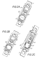
- the spring 12 extends into the recess 8 where it contacts the first terminal 1, the spring 12 thus constituting a conductor connecting the PTCR element 11 (which is itself in contact with the second terminal 2) to the first terminal 1.
- the H-shaped cut-outs 13 in the conductor spring 12 are such that the tension that is developed in the spring when it is pushed over the studs 10 causes the spring to bite into the studs so as to ensure proper firm location of the spring, with the PTCR element 11 held firmly in the recess 9 in good electrical contact with second terminal 2 and with good electrical contact made with first terminal 1.
- the switch operates as an automatically resetting switch which opens its contacts at a predetermined temperature in a rising temperature situation and subsequently recloses the contacts at a second, lower, predetermined temperature as the bimetal cools.
- the switch simply by the addition of the PTCR element and the connector spring the switch is reconfigured as a switch which will maintain its contacts open, once they have opened in a rising temperature situation, by virtue of heat developed in the PTCR element being conducted into the bimetal blade.
- the PTCR element is normally shortcircuited by the closed switch contacts so long as the switch is operating within its upper temperature limit, but carries current when the switch contacts open and experiences a rapid increase in resistance which dramatically reduces the current supply to the load as soon as the switch contacts open.
- the PTCR switch configuration can only be reset by switching off the power supply to the switch and its associated appliance and allowing time for the PTCR and bimetal to cool to its remake temperature.
- a manual reset version of the described switch could for example readily be configured by provision of a through hole in the body moulding of the switch, extending from a location intermediate the studs 10 on the rear of the body moulding through to a location on the front of the moulding underlying the leaf spring and bimetal blade assembly, and by provision of a push-rod in such through hole arranged so as when depressed to be capable of bearing upon the underside of the bimetal blade, an opening being provided in the leaf spring to allow the push-rod to access the bimetal.
- the bimetal selected to have such a wide differential that its automatic reset temperature would never be reached under normal conditions the bimetal would remain in its contacts-open condition until it was manually reset by application of a resetting force from the push-rod.
- the switch advantageously might be formed with a back-stop for limiting the contacts-opening movement of the leaf spring and/or of the bimetal blade and, in keeping with the aim of enhanced versatility, such backstop could be formed as a separate component, a plastics moulding for example, arranged to be clipped onto or otherwise detachably secured to the body moulding of the switch, though it could equally well be formed as an integral part of the body moulding.
- a mechanical and manually-releasable latch may be provided for latching the leaf spring in its contacts open condition.
- Figs. 3A and 3B show the form of the leaf spring 4 and it will be seen that the spring is generally rectangular with an elongate central cut-out 15 defining spaced-apart legs 16, and furthermore is tooled using a spherical punch in order to produce a domed region 17 in the area identified by the circle 18 in Fig. 3A and render the spring bistable in operation.
- the amount of doming is controlled such that the inner edges of the twisted spring legs 16 do not protrude above the central pillar 19 of the switch body portion 20 when the spring is welded to the respective part of switch terminal 2, and such that the spring will generate the requisite contact pressure without being too stiff for the bimetal 7 to overcome.
- Fig. 3A and 3B show the form of the leaf spring 4 and it will be seen that the spring is generally rectangular with an elongate central cut-out 15 defining spaced-apart legs 16, and furthermore is tooled using a spherical punch in order to produce a domed region 17 in the area identified by the circle
- FIG. 3D shows the switch body 20 configured to receive a push-rod 25 which is inserted into a complementarily profiled opening formed through the switch body before attachment of the leaf spring 4 and its actuating bimetal 7 to the switch.
- the push-rod 25 is also shown in enlarged view in Fig. 3D and it will be seen to have a hemispherical groove 26 in one face which forms a guiding surface with the central pillar 19 when the push-rod is inserted into the switch body 20.
- the push-rod additionally has an enlarged upper end or head 27 which serves to retain it in the switch and a pair of projecting abutments 28 are provided on the upper surface of this head 27 for contacting the inside edges of the legs 16 of the leaf spring 4 in order to effect resetting of the switch.
- Figs. 3C and 3E show the state of the switch under these circumstances.
- An advantage of such a switch configuration as compared to the previously mentioned manual reset switch employing a wide differential bimetal is that its operation is not dependent on the ambient temperature. Wide differential bimetal switches might for example be such that the bimetal will not remake above, say, -10°C without manual intervention and thus are of limited application by virtue of being ambient dependent.
- the switch of Figs. 3A to 3E is not limited in this way.
- the switch of the present invention is adapted to be configured selectively as an auto-reset switch, a manual reset switch, or a PTCR switch.
- the bimetal and leaf spring characteristics can be varied so as selectively to accommodate different switching requirements, for example by use of a more or less resistive material for the leaf spring so as to render the switch more or less current sensitive, without requiring any change in the geometry of the switch.
- the invention provides a versatile switch design which enables the diverse requirements of different applications to be satisfied by a single switch geometry which is designed to enable automatic manufacture and assembly of the various switch parts.
- a thermally-responsive electrical switch for use in domestic electrical appliances for switching off the electrical supply to the appliance in an over temperature situation is configured to be manufactured as an auto-reset switch, as a manual reset switch, or as a PTCR switch without significant manufacturing changes.
- the switch body is moulded plastics and incorporates first and second terminal parts, one of which provides a cantilever mounting for a switching element which moves to effect switching operations between its free end and the other terminal part.
- a bimetallic switch-actuating element is mounted on the switching element so as by its temperature-responsive movements to effect switch-operating movement of the switching element.
- the switch body is configured to be capable of accepting a PTCR element which is retained by a conductor such that the PTCR element is placed in a current conducting path through the switch when the switch contacts are opened, the heat developed in the PTCR element then holding the condition of the switch whilst substantially reducing the through current to the switch load.
Landscapes
- Physics & Mathematics (AREA)
- Thermal Sciences (AREA)
- Thermally Actuated Switches (AREA)
Abstract
Description
- This invention ccncerns improvements relating to thermally responsive electric switches for use for example in domestic electrical appliances such as fan heaters, toasters, cable reels etc. for switching off or substantially reducing the supply of power to the appliance in an overtemperature situation.
- Since the electrical currents that are drawn in use by appliances such as are mentioned above are significantly different from one appliance type to another, the requirement exists that a protective switch of the kind with which the present invention is concerned should be current insensitive or at least relatively so. Additional requirements are for automatically resetting thermal cut-out switches which break the power supply in response to a sensed overtemperature situation and then remake or reconnect the power supply after a time period such as to enable the appliance to cool sufficiently, manual reset cut-out switches which having operated in response to a sensed overtemperature situation will not reset until manually operated (such switches either having a wide differential so that their remake temperature is lower than normal ambient temperature or alternatively incorporating a latch mechanism), and cut-out switches incorporating a PTCR (Positive Temperature Coefficient of Resistance) element arranged to carry the load current once the switch breaks whereupon the resistance of the PTCR element increases and significantly reduces the power supply to the appliance and heat is developed in the PTCR element and serves to maintain the cut-out in its break condition.
- An exemplary cut-out switch incorporating a PTCR element as abovementioned is disclosed in DE-U-8617033.3 and comprises an electrically insulating body portion, first and second electrically-conductive terminal parts, the first terminal part serving additionally as a mounting for a first electrical contact of the switch and the second terminal part serving additionally as a mounting for a cantilevered electrically-conductive spring member having at its free end a second electrical contact of the switch, said first and second electrical contacts being arranged to effect switching operations in operation of the switch, and a bimetallic element being mounted on said spring member and being arranged to effect switch-operating movement thereof when it changes its state in response to a temperature change. The switch of DE-U-8617033.3 further comprises a PTCR element accommodated in a recess in the body portion of the switch, and leaf springs connect opposite sides of the PTCR element to the first and second terminal parts of the switch and also support the PTCR element in its recess.
- In addition to the abovementioned functional requirements, another problem faced by industry is that different countries, even within Europe, have different standards and electrical safety requirements. As a result, many different cut-out switches are currently available from various manufacturers to meet more or less specific requirements and the industry has not hitherto tackled the problem of how to configure a universal switch. Accordingly there is a requirement for a low cost, current insensitive, compact cut-out switch suitable for use in a variety of different applications.
- The present invention proposes to meet the abovementioned requirement by provision of a switch comprising a body portion, first and second electrically-conductive terminal parts, the first terminal part serving additionally as or as a mounting for a first electrical contact of the switch and the second terminal part serving additionally as a mounting for a cantilevered spring member having at its free end a second electrical contact of the switch, said first and second electrical contacts being arranged to effect switching operations in operation of the switch, a bimetallic element being mounted on said spring member and being arranged to effect switch-operating movement thereof when it changes its state in response to a temperature change, and the body portion of the switch furthermore including means for accommodating a PTCR element in electrical contact with said second terminal part and a mounting for accommodating a push-fit conductor element adapted when fitted to make electrical contact between said PTCR element and said first terminal part, the switch thus being configurable, selectively, as a switch with a PTCR element, in which case said PTCR element and said conductor element are provided in the switch, or as a switch without a PTCR element, in which case said PTCR element and said conductor element are omitted.
- As compared to the switch of DE-U-8617033.3 for example, which has many features in common with the switch of the present invention, the switch of the present invention provides for the optional inclusion of the PTCR element and the conductor element in the switch, whereas in the switch of DE-U-8617033.3 the PTCR element and its supporting and electrically contacting leaf springs are an essential part of the switch. There is no disclosure or suggestion in DE-U-8617033.3 of arranging the PTCR element to be an optional component of the switch so that the switch can be selectively configured as including or not including a PTCR element. The switch of DE-U-8617033.3 is thus exclusively a switch incorporating a PTCR element and is not selectively configurable to include or not include a PTCR element.
- In a preferred embodiment of the present invention which will be described in detail hereinafter the body portion of the switch is generally rectangular and defines spaced-apart end surfaces from which the first and second terminal parts project for enabling electrical connections to be made to the switch, an upper surface whereat the first terminal part of the switch is exposed and has affixed thereto the first electrical contact (namely the fixed contact) of the switch and whereat the second terminal part of the switch is exposed and has affixed thereto said cantilevered spring member, an under surface whereat a recess is defined for optionally accommodating a PTCR element and exposes an under surface of the second metal terminal part to contact by said PTCR element when fitted, whereat a mounting is provided for accommodating said conductor element in push-fit manner, and whereat an under surface of said first metal terminal part is exposed for being contacted by said conductor element when fitted, and two plain side surfaces. As an example, the body portion of such a switch might be 20mm long, 5mm high and 7mm wide.
- The cantilevered spring member conveniently comprises a leaf spring which advantageously may be attached to the second metal terminal part of the switch by means of a rivet formed as an integral part of the second metal terminal part. The bimetallic element preferably is a dished snap-acting blade and may conveniently be mounted on top of the cantilevered leaf spring by virtue of the leaf spring having released therefrom a pair of opposed attachment tabs between which the bimetallic blade is adapted to fit.
- The push-fit conductor element may advantageously comprise a conductor spring formed of beryllium copper or stainless steel for example, and may advantageously be retained to the moulded plastics body portion by virtue of the conductor spring being formed with one or more X-shaped, H-shaped, star-shaped or otherwise shaped cut-outs adapted to fit tightly over one or more studs moulded integrally with the body portion of the switch, the cut-out(s) of the conductor spring being designed to make an interference fit over the stud(s) and to dig into the stud(s) when put under load thereby ensuring that high spring forces are developed to hold the PTCR element immobile and ensure good electrical contact.
- The switch arrangement may be automatically resetting, where no PTCR element is provided, so that the switch will automatically reset once the bimetallic element cools after a switch-opening operation, or alternatively the switch may be configured to be manually reset. A manual reset switch may be obtained by use of a bimetallic element having a large differential or, as described hereinafter, by use of a spring member which is bistable so that it will move in response to switch-actuating movement of the bimetallic element in one sense but will not respond to bimetal movement in the opposite sense.
- As will become apparent from the following, the switch of the present invention can be configured as an auto-reset switch by omission of the PTCR element or as a PTCR switch by inclusion of the PTCR element. By provision of a reset push rod or the like in an accommodating part of the moulded plastics body portion and by use of a wide temperature differential bimetal and/or of a bistable spring member, the switch can also readily be configured as a manual reset switch.
- The above and other features of the invention are set forth with particularity in the appended claims and will be well understood from consideration of the following detailed description of exemplary embodiments given with reference to the accompanying drawings.
-
- Figures 1A to 1F illustrate the embodiment when configured as an auto-reset switch, Figs. 1A and 1B being side elevation views, Fig. 1C being a bottom plan view, Fig. 1D being a sectional side elevation view, Fig. 1E being a top plan view and Fig. 1F showing two different perspective views;
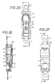
- Figures 2A to 2F illustrate the embodiment when configured as a PTCR switch, Fig. 2A showing a perspective view of the basic switch unit as viewed from the underside, Fig. 2B showing the unit with the PTCR element added, Fig. 2C showing the completed switch with the connector spring affixed, and Figs. 2D, 2E and 2F being views similar to Figs. 1C, 1D and 1E respectively; and
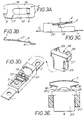
- Figures 3A to 3E illustrate a slightly modified form of the embodiment configured as a manual reset switch, Figs. 3A and 3B showing plan and side elevation views of a bistable leaf spring that is provided in this switch configuration, Fig. 3C being a side elevation view of the manual reset switch in condition where the bimetallic element of the switch has reset with falling temperature and yet the leaf spring remains in its "hot" position, Fig. 3D being a perspective showing (partly enlarged) of the form of a reset push rod of the switch and the manner of its incorporation into the switch, and Fig. 3E being a cross-sectional view through the switch in the plane of the push rod.
- Referring first to Figs. 1A to 1F, it will be seen that the switch comprises a moulded
plastics body portion 20 having first and secondmetal terminal parts body portion 20 for enabling electrical connection to be made to the switch. Within the envelope of thebody portion 20, as best seen in Fig. 1D, thefirst terminal part 1 serves as a mounting for afixed switch contact 3, and thesecond terminal part 2 serves as a mounting for a cantileveredleaf spring 4 which is affixed to theterminal part 2 by means of an integrally-formed rivet and carries at its free end a movingswitch contact 5 which is positioned to cooperate with the fixedcontact 3. Theleaf spring 4 has opposedattachment tabs 6 released therefrom and a dished, snap-actingbimetallic blade 7 is received between the tabs and thereby attached to theleaf spring 4. As best shown in Figs. 1A and 1B, thebimetal blade 7 is capable of adopting two different curvature states dependent upon its temperature, and in its "hot" condition as shown in Fig. 1A serves to lift the free end of theleaf spring 4 and thereby open the switch contacts, and in its "cold" condition as shown in Fig. 1B does not resist the natural tendency of theleaf spring 4 to hold the switch contacts closed. - On the opposite side of the
switch body portion 20 from the side which carries theleaf spring 4 and the other component parts abovementioned, there are provided arecess 8 providing access to thefirst terminal part 1, a recess 9 providing access to thesecond terminal part 2, and a body portion which bridges therecesses 8, 9 and has formed thereon a pair ofstuds 10. As shown in Figs, 2A to 2F, the recess 9 is designed to receive aPTCR element 11 in the form of a small cylindrical pellet, and thestuds 10 are designed to receive aconductor spring 12 having generally H-shaped cut-outs 13 which push-fit over the studs. Thespring 12 extends into therecess 8 where it contacts thefirst terminal 1, thespring 12 thus constituting a conductor connecting the PTCR element 11 (which is itself in contact with the second terminal 2) to thefirst terminal 1. The H-shaped cut-outs 13 in theconductor spring 12 are such that the tension that is developed in the spring when it is pushed over thestuds 10 causes the spring to bite into the studs so as to ensure proper firm location of the spring, with thePTCR element 11 held firmly in the recess 9 in good electrical contact withsecond terminal 2 and with good electrical contact made withfirst terminal 1. - As will be appreciated, in the configuration shown in Figs. 1A to 1F the switch operates as an automatically resetting switch which opens its contacts at a predetermined temperature in a rising temperature situation and subsequently recloses the contacts at a second, lower, predetermined temperature as the bimetal cools. In the configuration shown in Figs. 2A to 2F, simply by the addition of the PTCR element and the connector spring the switch is reconfigured as a switch which will maintain its contacts open, once they have opened in a rising temperature situation, by virtue of heat developed in the PTCR element being conducted into the bimetal blade. The PTCR element is normally shortcircuited by the closed switch contacts so long as the switch is operating within its upper temperature limit, but carries current when the switch contacts open and experiences a rapid increase in resistance which dramatically reduces the current supply to the load as soon as the switch contacts open. The PTCR switch configuration can only be reset by switching off the power supply to the switch and its associated appliance and allowing time for the PTCR and bimetal to cool to its remake temperature.
- A manual reset version of the described switch could for example readily be configured by provision of a through hole in the body moulding of the switch, extending from a location intermediate the
studs 10 on the rear of the body moulding through to a location on the front of the moulding underlying the leaf spring and bimetal blade assembly, and by provision of a push-rod in such through hole arranged so as when depressed to be capable of bearing upon the underside of the bimetal blade, an opening being provided in the leaf spring to allow the push-rod to access the bimetal. With the bimetal selected to have such a wide differential that its automatic reset temperature would never be reached under normal conditions, the bimetal would remain in its contacts-open condition until it was manually reset by application of a resetting force from the push-rod. To avoid the risk of unduly stressing the leaf spring and/or the bimetal blade during operation of the push-rod, the switch advantageously might be formed with a back-stop for limiting the contacts-opening movement of the leaf spring and/or of the bimetal blade and, in keeping with the aim of enhanced versatility, such backstop could be formed as a separate component, a plastics moulding for example, arranged to be clipped onto or otherwise detachably secured to the body moulding of the switch, though it could equally well be formed as an integral part of the body moulding. As an alternative to the provision of a push-rod arrangement, or in addition thereto, a mechanical and manually-releasable latch may be provided for latching the leaf spring in its contacts open condition. - As an alternative to using a wide differential bimetal in a manual reset version of the switch, the moving contact carrying leaf spring of the switch could itself be made bistable and arranged so that it will not return to its contacts closed "cold" condition in the absence of manual intervention even when the bimetal has reset. Such a manual reset version of the subject switch is illustrated in Figures 3A to 3E of the accompanying drawings wherein the same reference numerals are used to identify like parts to those correspondingly identified in the other drawing figures.
- Figs. 3A and 3B show the form of the
leaf spring 4 and it will be seen that the spring is generally rectangular with an elongate central cut-out 15 defining spaced-apart legs 16, and furthermore is tooled using a spherical punch in order to produce adomed region 17 in the area identified by thecircle 18 in Fig. 3A and render the spring bistable in operation. The amount of doming is controlled such that the inner edges of thetwisted spring legs 16 do not protrude above thecentral pillar 19 of theswitch body portion 20 when the spring is welded to the respective part ofswitch terminal 2, and such that the spring will generate the requisite contact pressure without being too stiff for the bimetal 7 to overcome. Fig. 3D shows theswitch body 20 configured to receive a push-rod 25 which is inserted into a complementarily profiled opening formed through the switch body before attachment of theleaf spring 4 and itsactuating bimetal 7 to the switch. The push-rod 25 is also shown in enlarged view in Fig. 3D and it will be seen to have ahemispherical groove 26 in one face which forms a guiding surface with thecentral pillar 19 when the push-rod is inserted into theswitch body 20. The push-rod additionally has an enlarged upper end orhead 27 which serves to retain it in the switch and a pair of projectingabutments 28 are provided on the upper surface of thishead 27 for contacting the inside edges of thelegs 16 of theleaf spring 4 in order to effect resetting of the switch. - In operation of the thus described manual reset version of the subject switch, when the bimetal heats to its operating temperature and snaps into its "hot" configuration, it lifts the contact-carrying end of
leaf spring 4 and reverses the twist in itslegs 16, thereby causing the leaf spring to snap to its oppositely dished other stable state. The switch is thus opened and disrupts the current supply to the appliance or whatever is being protected. As the bimetal cools, it is permitted to creep away from thecentral pillar 19, against which it pushes for opening the switch, whilst being held in place by thetabs 6 provided on theleaf spring 4 and, on reaching its remake temperature, it snaps back to its "cold" condition. The contacts however remain open by virtue of the bistable nature of theleaf spring 4 which cannot reset without manual intervention. Figs. 3C and 3E show the state of the switch under these circumstances. In order to reset the switch from this condition, it is necessary only to push the push-rod 25 in the direction of the arrow shown in Fig. 3E so as to cause the two abutments 23 to contact the inside edges of thelegs 16 and reverse the curvature of the legs, thereby allowing the switch contacts to remake when the reset force on the push-rod is removed. An advantage of such a switch configuration as compared to the previously mentioned manual reset switch employing a wide differential bimetal is that its operation is not dependent on the ambient temperature. Wide differential bimetal switches might for example be such that the bimetal will not remake above, say, -10°C without manual intervention and thus are of limited application by virtue of being ambient dependent. The switch of Figs. 3A to 3E is not limited in this way. - As described in the foregoing, the switch of the present invention is adapted to be configured selectively as an auto-reset switch, a manual reset switch, or a PTCR switch. The bimetal and leaf spring characteristics can be varied so as selectively to accommodate different switching requirements, for example by use of a more or less resistive material for the leaf spring so as to render the switch more or less current sensitive, without requiring any change in the geometry of the switch. As a result, the invention provides a versatile switch design which enables the diverse requirements of different applications to be satisfied by a single switch geometry which is designed to enable automatic manufacture and assembly of the various switch parts.
- A summary of the foregoing might be worded as follows: a thermally-responsive electrical switch for use in domestic electrical appliances for switching off the electrical supply to the appliance in an over temperature situation is configured to be manufactured as an auto-reset switch, as a manual reset switch, or as a PTCR switch without significant manufacturing changes. The switch body is moulded plastics and incorporates first and second terminal parts, one of which provides a cantilever mounting for a switching element which moves to effect switching operations between its free end and the other terminal part. A bimetallic switch-actuating element is mounted on the switching element so as by its temperature-responsive movements to effect switch-operating movement of the switching element. The switch body is configured to be capable of accepting a PTCR element which is retained by a conductor such that the PTCR element is placed in a current conducting path through the switch when the switch contacts are opened, the heat developed in the PTCR element then holding the condition of the switch whilst substantially reducing the through current to the switch load. By omission of the PTCR element, an auto-reset switch is obtained, and by selection of the characteristics of the bimetallic element and/or arranging the switching element to be bistable, a manual reset version of the switch can be obtained.
- The invention having been described in the foregoing by reference to specific embodiments, it is to be well understood that the invention is not limited to the specific embodiments described and that modifications and variations could be made thereto without departure from the scope of the invention as defined by the claims.
Claims (11)
- A thermally responsive electrical switch comprising a body portion (20), first and second electrically conductive terminal parts (1,2) the first terminal part (1) serving additionally as or as a mounting for a first electrical contact (3) of the switch and the second terminal part (2) serving additionally as a mounting for a cantilevered electrically-conductive spring member (4) having at its free end a second electrical contact (5) of the switch, said first and second electrical contacts (3, 5) being arranged to effect switching operations in operation of the switch, a bimetallic element (7) being mounted on said spring member (4) and being arranged to effect switch-operating movement thereof when it changes its state in response to a temperature change, characterized in that the body portion (20) of the switch furthermore includes means (9) for accommodating a PTCR element (11) in electrical contact with said second terminal part (2) and a mounting (10) for accommodating a push-fit conductor element (12) adapted when fitted to make electrical contact between said PTCR element (11) and said first terminal part (1), the switch thus being configurable, selectively, as a switch with a PTCR element, in which case said PTCR element (11) and said conductor element (12) are provided in the switch, or as a switch without a PTCR element, in which case said PTCR element (11) and said conductor element (12) are omitted.
- A switch as claimed in claim 1 wherein the body portion (20) of the switch is formed to define a recess (9) for accommodating said PTCR element (11) in electrical and thermal contact with said second terminal part (2) and the push-fit conductor element (12) is adapted when fitted to serve as a retainer for holding said PTCR element (11) in said recess (9) under spring pressure and additionally to make electrical contact between said PTCR element (11) and said first terminal part (1).
- A switch as claimed in claim 2 wherein the moulded plastics body portion (20) of the switch is generally rectangular and defines spaced-apart end surfaces from which the first and second metal terminal parts (1,2) project for enabling electrical connections to be made to the switch, an upper surface whereat the first terminal part (1) of the switch is exposed and has affixed thereto the first electrical contact (3) of the switch and whereat the second terminal part (2) of the switch is exposed and has affixed thereto said cantilevered spring member (4), an under surface whereat said recess (9) is defined and exposes an under surface of the second metal terminal part (2) to contact by said PTCR element (11) when fitted, whereat said mounting (10) is provided for said push-fit conductor element (12), and whereat an under surface of said first metal terminal part (1) is exposed for being contacted by said conductor element (12) when fitted, and two plain side surfaces.
- A switch as claimed in claim 2 or 3 wherein the cantilevered spring member (4) comprises a leaf spring and the bimetallic element (7) comprises a dished snap-acting blade mounted on top of the cantilevered leaf spring by virtue of the leaf spring having released therefrom a pair of opposed attachment tabs (6) between which the bimetallic blade is adapted to fit.
- A switch as claimed in any of claims 2 to 4 wherein the push-fit conductor element (12) comprises a conductor spring retained to the moulded plastics body portion (20) by virtue of the conductor spring being formed with one or more X-shaped, H-shaped, star-shaped or otherwise shaped cut-outs (13) adapted to fit tightly over one or more studs (10) moulded integrally with the body portion (20) of the switch, the cut-out(s) (13) of the conductor spring (12) being designed to make an interference fit over the stud(s) (10) and to dig into the stud(s) (10) when put under load thereby ensuring that high spring forces are developed to hold the PTCR element (11) immobile and ensure good electrical contact.
- A switch as claimed in any of the preceding claims when configured as an auto-reset switch, there being no PTCR element (11) in said switch.
- A switch as claimed in any of claims 1 to 5 when configured as a PTCR switch, a PTCR element (11) being accommodated and retained by said body portion (20) by means of a said conductor element (12).
- A switch as claimed in any of claims 1 to 5 when configured as a manual reset switch, there being a push rod (25) accommodated in an accommodating part of the switch body (20) for enabling a bistable bimetallic element (7) and/or a bistable spring member (4) to be manually reset.
- A switch as claimed in claim 8 wherein the bimetallic element (7) is automatically resetting and the spring member (4) is bistable, the bimetallic element (7) being capable of operating the switch in one sense by imparting its movement to the spring member (4), but being incapable of imparting its opposite movement to effect opposite movement of the spring member (4).
- A switch as claimed in claim 9 wherein the spring member (4) comprises a spring blade having a central cut-out (15) defining spaced apart legs (16), and a region (17) of the spring blade is dished so as to render the blade bistable, movement of the blade between its two stable conditions being accompanied by a twisting movement of said legs (16), the push rod (25) operating on the legs (16) so as to cause them to reverse their twist direction and thereby cause the blade (4) to move to its opposite stable condition.
- A switch as claimed in any of the preceding claims incorporating a manually-releasable latching element for holding the switch in an operated condition.
Applications Claiming Priority (3)
| Application Number | Priority Date | Filing Date | Title |
|---|---|---|---|
| GB9100186 | 1991-01-04 | ||
| GB919100186A GB9100186D0 (en) | 1991-01-04 | 1991-01-04 | Improvements relating to thermally responsive electric switches |
| PCT/GB1992/000022 WO1992012524A1 (en) | 1991-01-04 | 1992-01-06 | Thermally responsive electric switch |
Publications (2)
| Publication Number | Publication Date |
|---|---|
| EP0565577A1 EP0565577A1 (en) | 1993-10-20 |
| EP0565577B1 true EP0565577B1 (en) | 1996-08-14 |
Family
ID=10687988
Family Applications (1)
| Application Number | Title | Priority Date | Filing Date |
|---|---|---|---|
| EP92902253A Expired - Lifetime EP0565577B1 (en) | 1991-01-04 | 1992-01-06 | Thermally responsive electric switch |
Country Status (6)
| Country | Link |
|---|---|
| EP (1) | EP0565577B1 (en) |
| AU (1) | AU1159392A (en) |
| DE (1) | DE69212804T2 (en) |
| ES (1) | ES2090603T3 (en) |
| GB (1) | GB9100186D0 (en) |
| WO (1) | WO1992012524A1 (en) |
Family Cites Families (5)
| Publication number | Priority date | Publication date | Assignee | Title |
|---|---|---|---|---|
| DE7531355U (en) * | 1975-10-03 | 1978-04-27 | Inter Control Hermann Koehler Elektrik Gmbh & Co Kg, 8500 Nuernberg | Resettable temperature limiter |
| DE3104827A1 (en) * | 1981-02-11 | 1982-08-19 | Limitor AG, 8022 Zürich | "BIMETAL TEMPERATURE SWITCH" |
| AT383696B (en) * | 1982-03-03 | 1987-08-10 | Electrovac | THERMAL SWITCH |
| DE8617033U1 (en) * | 1986-06-26 | 1986-08-14 | Temtech-Temperatur-Technik Hans-Peter Bojer, 7530 Pforzheim | Bimetal switch |
| GB2227884A (en) * | 1988-12-28 | 1990-08-08 | Otter Controls Ltd | Snap-acting bimetal blade |
-
1991
- 1991-01-04 GB GB919100186A patent/GB9100186D0/en active Pending
-
1992
- 1992-01-06 DE DE69212804T patent/DE69212804T2/en not_active Expired - Fee Related
- 1992-01-06 ES ES92902253T patent/ES2090603T3/en not_active Expired - Lifetime
- 1992-01-06 WO PCT/GB1992/000022 patent/WO1992012524A1/en not_active Ceased
- 1992-01-06 EP EP92902253A patent/EP0565577B1/en not_active Expired - Lifetime
- 1992-01-06 AU AU11593/92A patent/AU1159392A/en not_active Abandoned
Also Published As
| Publication number | Publication date |
|---|---|
| EP0565577A1 (en) | 1993-10-20 |
| DE69212804D1 (en) | 1996-09-19 |
| WO1992012524A1 (en) | 1992-07-23 |
| DE69212804T2 (en) | 1997-02-20 |
| GB9100186D0 (en) | 1991-02-20 |
| ES2090603T3 (en) | 1996-10-16 |
| AU1159392A (en) | 1992-08-17 |
Similar Documents
| Publication | Publication Date | Title |
|---|---|---|
| US4319126A (en) | Temperature dependent electric current-regulator-or-limiting switching element for electrical appliances: especially electrically heated devices | |
| US3443259A (en) | Creepless snap-acting thermostatic switch | |
| US5847638A (en) | Thermal circuit protector and switch | |
| US5796327A (en) | Thermally responsive electrical switches | |
| GB2117568A (en) | Immersed element protection | |
| US5929742A (en) | Trip-free, manual reset thermostat | |
| US5003282A (en) | Trip free/reset free manual reset | |
| EP0202939A2 (en) | Electric immersion heating elements and controls therefor | |
| US5982269A (en) | Electric switch and thermal protector | |
| GB2339088A (en) | Cordless kettle connector with bimetallic overtemperature controls | |
| KR20050117468A (en) | Manual-reset thermostat | |
| US5703560A (en) | Thermostat with one-piece reset mechanism and contact assembly | |
| US4255736A (en) | Thermal protective switch | |
| GB2252674A (en) | Thermally responsive electrical switches | |
| EP1517346B1 (en) | Improvements relating to thermal controls for electric heating elements | |
| US3256413A (en) | Wafer thin thermostat | |
| WO1992012524A1 (en) | Thermally responsive electric switch | |
| US2513748A (en) | Electric switch | |
| US2664480A (en) | Circuit breaker | |
| US3946352A (en) | Thermally responsive switch | |
| EP0645051A1 (en) | Energy regulators | |
| US4001751A (en) | Non-resettable thermostat | |
| US4633211A (en) | Electrical switch construction and method of making the same | |
| EP1249851B1 (en) | Improvements relating to the control of electric heating elements | |
| US4268813A (en) | Resettable thermal cut-off switch |
Legal Events
| Date | Code | Title | Description |
|---|---|---|---|
| PUAI | Public reference made under article 153(3) epc to a published international application that has entered the european phase |
Free format text: ORIGINAL CODE: 0009012 |
|
| 17P | Request for examination filed |
Effective date: 19930708 |
|
| AK | Designated contracting states |
Kind code of ref document: A1 Designated state(s): DE ES FR GB IT NL |
|
| 17Q | First examination report despatched |
Effective date: 19940812 |
|
| GRAH | Despatch of communication of intention to grant a patent |
Free format text: ORIGINAL CODE: EPIDOS IGRA |
|
| GRAH | Despatch of communication of intention to grant a patent |
Free format text: ORIGINAL CODE: EPIDOS IGRA |
|
| GRAA | (expected) grant |
Free format text: ORIGINAL CODE: 0009210 |
|
| AK | Designated contracting states |
Kind code of ref document: B1 Designated state(s): DE ES FR IT NL |
|
| RBV | Designated contracting states (corrected) |
Designated state(s): DE ES FR IT NL |
|
| REF | Corresponds to: |
Ref document number: 69212804 Country of ref document: DE Date of ref document: 19960919 |
|
| ET | Fr: translation filed | ||
| REG | Reference to a national code |
Ref country code: ES Ref legal event code: FG2A Ref document number: 2090603 Country of ref document: ES Kind code of ref document: T3 |
|
| ITF | It: translation for a ep patent filed | ||
| REG | Reference to a national code |
Ref country code: ES Ref legal event code: FG2A Ref document number: 2090603 Country of ref document: ES Kind code of ref document: T3 |
|
| PLBE | No opposition filed within time limit |
Free format text: ORIGINAL CODE: 0009261 |
|
| STAA | Information on the status of an ep patent application or granted ep patent |
Free format text: STATUS: NO OPPOSITION FILED WITHIN TIME LIMIT |
|
| 26N | No opposition filed | ||
| PGFP | Annual fee paid to national office [announced via postgrant information from national office to epo] |
Ref country code: DE Payment date: 20030116 Year of fee payment: 12 |
|
| PGFP | Annual fee paid to national office [announced via postgrant information from national office to epo] |
Ref country code: NL Payment date: 20030130 Year of fee payment: 12 |
|
| PGFP | Annual fee paid to national office [announced via postgrant information from national office to epo] |
Ref country code: ES Payment date: 20030218 Year of fee payment: 12 |
|
| PG25 | Lapsed in a contracting state [announced via postgrant information from national office to epo] |
Ref country code: ES Free format text: LAPSE BECAUSE OF NON-PAYMENT OF DUE FEES Effective date: 20040107 |
|
| PG25 | Lapsed in a contracting state [announced via postgrant information from national office to epo] |
Ref country code: NL Free format text: LAPSE BECAUSE OF NON-PAYMENT OF DUE FEES Effective date: 20040801 |
|
| PG25 | Lapsed in a contracting state [announced via postgrant information from national office to epo] |
Ref country code: DE Free format text: LAPSE BECAUSE OF NON-PAYMENT OF DUE FEES Effective date: 20040803 |
|
| NLV4 | Nl: lapsed or anulled due to non-payment of the annual fee |
Effective date: 20040801 |
|
| PG25 | Lapsed in a contracting state [announced via postgrant information from national office to epo] |
Ref country code: IT Free format text: LAPSE BECAUSE OF NON-PAYMENT OF DUE FEES Effective date: 20050106 |
|
| REG | Reference to a national code |
Ref country code: ES Ref legal event code: FD2A Effective date: 20040107 |
|
| PGFP | Annual fee paid to national office [announced via postgrant information from national office to epo] |
Ref country code: FR Payment date: 20080117 Year of fee payment: 17 |
|
| REG | Reference to a national code |
Ref country code: FR Ref legal event code: ST Effective date: 20091030 |
|
| PG25 | Lapsed in a contracting state [announced via postgrant information from national office to epo] |
Ref country code: FR Free format text: LAPSE BECAUSE OF NON-PAYMENT OF DUE FEES Effective date: 20090202 |