EP0565384A1 - Single axis rate sensor noise reduction - Google Patents
Single axis rate sensor noise reduction Download PDFInfo
- Publication number
- EP0565384A1 EP0565384A1 EP93302811A EP93302811A EP0565384A1 EP 0565384 A1 EP0565384 A1 EP 0565384A1 EP 93302811 A EP93302811 A EP 93302811A EP 93302811 A EP93302811 A EP 93302811A EP 0565384 A1 EP0565384 A1 EP 0565384A1
- Authority
- EP
- European Patent Office
- Prior art keywords
- signal
- primary
- pick
- transducer
- loop
- Prior art date
- Legal status (The legal status is an assumption and is not a legal conclusion. Google has not performed a legal analysis and makes no representation as to the accuracy of the status listed.)
- Granted
Links
Images



Classifications
-
- G—PHYSICS
- G01—MEASURING; TESTING
- G01C—MEASURING DISTANCES, LEVELS OR BEARINGS; SURVEYING; NAVIGATION; GYROSCOPIC INSTRUMENTS; PHOTOGRAMMETRY OR VIDEOGRAMMETRY
- G01C19/00—Gyroscopes; Turn-sensitive devices using vibrating masses; Turn-sensitive devices without moving masses; Measuring angular rate using gyroscopic effects
- G01C19/56—Turn-sensitive devices using vibrating masses, e.g. vibratory angular rate sensors based on Coriolis forces
- G01C19/567—Turn-sensitive devices using vibrating masses, e.g. vibratory angular rate sensors based on Coriolis forces using the phase shift of a vibration node or antinode
- G01C19/5691—Turn-sensitive devices using vibrating masses, e.g. vibratory angular rate sensors based on Coriolis forces using the phase shift of a vibration node or antinode of essentially three-dimensional [3D] vibrators, e.g. wine glass-type vibrators
Definitions
- the present invention relates to noise reduction in rate sensors and relates particularly, but not exclusively, to noise reduction in single axis rate sensors.
- Figure 1 shows a system diagram by single axis rate sensor of the type described in British Patent Numbers GB 2061502 and GB 2154739.
- the cylinder of the rate sensor is driven into resonance by applying an oscillating electronic signal to the drive transducers.
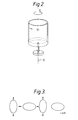
- the vibration pattern, viewed from the top, of the resonant mode is shown in Figure 2.
- the primary loop maintains this resonance by ensuring a 90 degree phase shift between the primary drive transducers and the primary pick-off transducers.
- the rate sensor When the rate sensor is rotated, the resonant node rotates with respect to the cylinder, and the signal can be detected on the secondary pick-off transducer. This signal is amplified and fed back to the secondary drive transducer in order to null it to zero. The strength of this nulling signal is proportional to a rotation rate. The signal is demodulated and outputted as a DC rate signal.
- the vibration pattern can have a different shape to that shown in Figure 2. However, the vibration pattern must have nodes and anti nodes occurring cylindrically around the perimeter of the cylinder.
- the cy- linderdoes not have to be driven exactly at resonance - but in practice it is desirable to do so.
- the resonant body neither has to be circular, nor cylindrical. Hemispheres and rings can be used. However, it is desirable that the oscillating nodes seen by primary and secondary electronic circuits (referred to as the primary and secondary resonances) have the same, or nearly the same, resonant frequency.
- a metal cylinder closed at one end and supported by a stem, is driven into resonance using piezo electric elements stuck onto the metal cylinder, see for example Figure 2.
- the piezo electric element are also used to pick-off the movement.
- phase locked loop comprises a phase detector, low pass filter and a voltage control oscillator (VCO).
- VCO voltage control oscillator
- the phase detector is configured such that it outputs a signal C which is proportional to the phase difference between the signals at its inputs.
- the phase detector used here has a zero output when the inputs are in quadrature, ie it is a quadrature phase detector.
- phase detector input signal (A and B) are in quadrature, and thus the cylinder is on resonance. If the phase of the signal at B alters, this is sensed by the phase detector, which outputs a correction signal C which is filtered and used to control the phase of the VCO signal.
- the oscillation frequency for typical cylinders is 8 kHz to 25 kHz, depending on size and performance. These frequencies are well above the typical at random vibration spectra, say 20 Hz to 3 kHz. Nevertheless it is found in practice that random vibrations are coupled through to the cylinder and that the pick-off transducers act like microphones, ie output a signal approximately proportional to the input vibration. This microphonic process is linear, ie no mixing of signals occurs at this stage as far as it is possible to detect. Typical phase-lock loop integrated circuits for this frequency of operation use digital techniques to implement the phase detector.
- Signals A and B are in effect passed through comparators to generate square waves which are then processed digitally to measure the phase difference between them.
- the square wave generation process mixes the microphonic noise with the carrier signal on B.
- the subsequent phase detection process is then corrupted by the microphonic noise which appears back at base band and corrupts the phase error signal at C.
- Signal C plus microphonic noise is then filtered and used to control the VCO.
- the VCO is then modulated such that the squared up signal A tracks the squared up signal plus microphone noise at B within the band width of the loop.
- the net affect of this is that the primary drive signal is modulated by noise, where the noise modulation appears as phase modulation around the carrier.
- any signal seen on the secondary pick-off transducer is amplified, filtered, and fed back to the secondary drive transducer in order to null the secondary pick-off signal to zero.
- the amplitude of the nulling signal is a measurement of rotation rate. This amplitude is measured by demodulating the secondary drive signal with respect to the primary pick-off signal which is phase shifted by 90 degrees. If the primary drive signal contains noise around the carrier, this noise would also be seen by the second pick-off transducer- either when the device is turned or as a modulation of a bias signal arising from manufacturing tolerances.
- the secondary drive signal must null the noise signal, and there will therefore be noise present around the carrier at the signal input to the demodulator.
- the rate output will therefore have a noise component at baseband.
- a second mechanism for noise arises from the original microphonic baseband noise present on the primary pick-off transducer. If the primary pick-off signal is squared up in a comparator in order to use it as the reference input for the demodulator, then the microphonic noise will be mixed with the carrier signal causing sidebands around the carrier. If a signal, bias, or quadrature bias signal exists on the demodulator input, then the noise around the carrier on the reference input would be mixed down to baseband and appear as a baseband noise component on the rate output.
- cylinders particularly those made from piezo electric materials, output microphonic signals in respect to the input vibration noise.
- Practical phase-locked loop chips utilising comparators at their inputs mix the microphonic noise with the carrier at the signal input. The effect is to phase modulate the signal from the VCO - ie the primary drive signal onto the cylinder. Noise present on secondary pick-off transducer is nulled by the secondary loop.
- the signal input to the demodulator has noise around the signal component.
- the demodulator will mix the noise seen at the signal input down to baseband, and the rate sensor is therefore sensitive to vibration.
- Practical demodulators often use analogue switches to perform the demodulation process. This require the reference input to be a square wave.
- the reference is derived by squaring up the primary pick-off signal and passing it through a comparator. This process mixes the microphonic noise and the resulting demodulating process mixes the noise down to baseband if there is a bias, quadrature, or signal component at the demodulator signal input.
- the present invention provides a sensor for detecting rotational movement about an axis including a cylinder positioned about said axis, primary and secondary drive transducers for applying radial vibrations to said cylinder, primary and secondary pick-off transducers for detecting the presence of vibrations induced in said cylinder, primary control loop for receiving a signal from the primary pick-off transducer and maintaining resonance by generating a ninety degree phase shift between the primary drive transducer and the primary pick-off transducer, a secondary control loop for receiving a signal from the secondary pick-off transducer indicative of rotation thereof and for directing said signal to the secondary drive transducer so as to null it to zero, said primary control loop including a phase locked loop having a phase detector configured to operate at quadrature, a low pass filter and a voltage controlled oscillator.
- the demodulator and loop filter combination will be a linear device which will not mix the microphonic base band signal with the carrier, there will therefore be a reduction and possibly an elimination of the modulation of the voltage controlled oscillator by microphonic noise.
- the sensor includes a connection means for connecting a reference signal from the primary loop demodulator to a reference input in the output demodulator.
- This arrangement ensures that the output demodulator's phase reference is held at 90 degrees with respect to the primary pick-off signal to within the phase-error accuracy of the voltage control oscillator control loop. Phase errors in the output demodulator are very undesirable because they induce drifts.
- this aspect reduces and may even eliminate, phase noise on the output demodulator reference input, which in turn reduces another noise- under-vibration source.
- the senor includes a gain control signal deriving means including a control demodulator for demodulating a signal B from the primary pick-off at 90 degrees with respect to the voltage controlled oscillator output signal E.
- a gain control signal deriving means including a control demodulator for demodulating a signal B from the primary pick-off at 90 degrees with respect to the voltage controlled oscillator output signal E.
- the senor may also include a logarithmic amplifier for amplifying a signal B from the primary pick-off prior to the signal being passed to the demodulator of the phase locked loop.
- the amplifier provides an increase gain at small signal amplitudes (eg when the phase-locked loop is not locked) in order to improve the sensors start-up characteristics.
- the senor includes a high pass filter in the secondary circuit for filtering a signal from the secondary pick-off transducer prior to signal being passed to the secondary loop filter.
- a high pass filter in the secondary circuit for filtering a signal from the secondary pick-off transducer prior to signal being passed to the secondary loop filter.
- This arrangement helps reject the sideband microphonic noise from the second pick-off electrode. If the high pass filter is not filtered, then microphonic noise can be amplified by the filter and fed back to the cylinder on the secondary drive electrode. Moreover, it is fed to the output demodulator which must then reject the sideband noise.
- the secondary loop filter comprises in phase and quadrature demodulators to transfer bypass signals to baseband, in phase and quadrature filters, and in phase and quadrature modulators to translate sideband information back to baseband for filtering an inphase-signal and a quadrature signal.
- An integrator may be included in the filter stage. The process is carried out in both the inphase-signal and the quadrature signal where the phases are with respect to the voltage control oscillator output.
- the combination of high-pass (or bypass) filtering together with demodulation/filtering/remodulation ensures that microphonic noise is rejected in the secondary loop.
- a gain stage may be added to the circuitry in order to amplify the primary drive signal before it is applied to the cylinder. This will have the advantage of increasing the vibration signal with respect to the measured microphonic noise. This gain stage will probably be implemented using a transformer.
- the size and shape of the cylinder are such as to ensure the maximum drive signal is applied to cylinder.
- a vibrating rate sensor for detecting rotational movement about an axis includes a cylinder 12 positioned about said axis X, primary and secondary drive transducers 14, 16 forapplying radial vibration to said cylinder, primary and secondary pick-off transducers 18, 20fordetecting the presence of vibration induced in said cylinder 12 and primary and secondary control loops 22, 23.
- the primary control loop 22 is provided for receiving a signal from the primary pick-off transducer 18 and for maintaining resonance of the structure by generating a 90 degree phase shift between the primary drive transducer 14 and the primary pick-off transducer 18.
- the secondary control loop 23 is provided for receiving a signal from the secondary pick-off transducer 22 which is indicative of rotation of the structure.
- the primary control loop 22 includes a phase locked loop (PLL) having a phase detector 30 configured to operate at quadrature, a low pass filter 32 and a voltage controlled oscillator 34.
- the voltage control oscillator 34 provides an output signal for driving the primary drive transducer 14 and a 90 degree phase shifted reference signal (ref) for returning to phase detector 30 to form portion of the phase locked loop.
- the operation of such primary drive circuits is well known in the art and is therefore not described in further detail herein. It should be noted, however, that in this arrangement a phase detector is implemented from the phase lock loop with a demodulator operated at quadrature. This demodulator plus loop- filter combination is a linear device which will not mix the microphonic baseband signal with the carrier. The arrangement therefore reduces, and may even eliminate, demodulation of the voltage control oscillator by microphonic noise.
- the reference signal to the primary loop demodulator may also be connected to the reference input of the output demodulator 26. This would ensure that the output demodulator's phase reference is held at 90 degrees with respect to the primary pick-off signal to within the phase-error accuracy of the voltage control oscillator control loop.
- This arrangement reduces and possibly eliminates phase errors in the output demodulator which can result in induced drifts.
- this arrangement may even eliminate phase noise from the output demodulator reference input which in turn would reduce other noise under vibration source.
- a gain control signal deriving means shown generally at 42 and comprising a demodulator 44, control at 46 and again control device 48.
- the gain control signal is derived by demodulating the primary pick-off signal at 90 degrees with respect to the voltage control oscillator output signal. This ensures that microphonic noise does not amplitude modulate the primary drive signal thus further reducing noise in the sensor.
- Alog- arithmic amplifier 50 may be provided for amplifying a signal B on the primary pick-off transducer 18 prior to said signal being passed to the demodulator 30 of the phase locked loop.
- This arrangement would provide increased gain at small signal amplitudes (eg when the phase-locked loop is not locked) and would improve the sensors start-up characteristics. It should be noted, however, care should be taken to ensure that mixing of the microphonic noise with the carrier signal provides a negligible increase of noise under vibration. However, once locked, the increase gain could be switched out of the control loop.
- Figure 9 illustrates a further arrangement of the present invention in which a high pass filter 52 is incorporated into the secondary control circuit.
- the high pass filter 52 acts to fitter the signal from the secondary pick-off transducer 20 prior to said signal being passed to the secondary loop filter. Failure to provide the high pass filter 52 could result in the amplification of microphonic noise by the secondary loop filter and feedback to the cylinder on the secondary drive. In addition to this, the signal is fed to the demodulator 26 which must then reject the baseband noise.
- the secondary filter may be implemented using a demodulation stage 54, 56 to transfer bandpass signals to baseband, a filter stage 58, 60 possibly containing an integrator and a modulation stage 52, 54 to translate baseband information back to bandpass.
- This process is carried out on both the inphase signal (P) and the quadrature signal (Q) where the phases are with respect to the voltage control oscillator output.
- stage 66 may be added to amplify the primary drive signal before it is applied to the cylinder via the primary drive transducer 14.
- This gain stage could be implemented using a transformer. Such an arrangement would ensure that the vibration signal is increased with respect to the measured microphonic noise.
- the primary drive electrode 14 is preferably optimised in size and shape in order to ensure the maximum drive apply to the cylinder. This would allow an increase in the vibration signal with respect to the measured microphonic noise.
- the optimum angle attended by the electrode is 45 degrees and the primary drive signal should be applied to the opposite electrode as perthe presently known arrangement.
- a primary drive signal which is inverted can be applied to the electrode at 90 degrees to the primary drive electrodes, while the other electrode at 90 degrees is used as a primary pick-off transducer.
Landscapes
- Physics & Mathematics (AREA)
- Engineering & Computer Science (AREA)
- General Physics & Mathematics (AREA)
- Radar, Positioning & Navigation (AREA)
- Remote Sensing (AREA)
- Gyroscopes (AREA)
- Transmission And Conversion Of Sensor Element Output (AREA)
Abstract
Description
- The present invention relates to noise reduction in rate sensors and relates particularly, but not exclusively, to noise reduction in single axis rate sensors.
- Figure 1 shows a system diagram by single axis rate sensor of the type described in British Patent Numbers GB 2061502 and GB 2154739. The cylinder of the rate sensor is driven into resonance by applying an oscillating electronic signal to the drive transducers. The vibration pattern, viewed from the top, of the resonant mode is shown in Figure 2. There are anti nodes of maximum radial vibration and nodes of minimum radial vibration present. The primary loop maintains this resonance by ensuring a 90 degree phase shift between the primary drive transducers and the primary pick-off transducers.
- When the rate sensor is rotated, the resonant node rotates with respect to the cylinder, and the signal can be detected on the secondary pick-off transducer. This signal is amplified and fed back to the secondary drive transducer in order to null it to zero. The strength of this nulling signal is proportional to a rotation rate. The signal is demodulated and outputted as a DC rate signal.
- The vibration pattern can have a different shape to that shown in Figure 2. However, the vibration pattern must have nodes and anti nodes occurring cylindrically around the perimeter of the cylinder. The cy- linderdoes not have to be driven exactly at resonance - but in practice it is desirable to do so. The resonant body neither has to be circular, nor cylindrical. Hemispheres and rings can be used. However, it is desirable that the oscillating nodes seen by primary and secondary electronic circuits (referred to as the primary and secondary resonances) have the same, or nearly the same, resonant frequency.
- In Figure 1 a metal cylinder, closed at one end and supported by a stem, is driven into resonance using piezo electric elements stuck onto the metal cylinder, see for example Figure 2. The piezo electric element are also used to pick-off the movement.
- GB2154739 describes a similar device of unitary construction made from piezo electric material where the drive and pick-off transducers are formed by polarizing the material between electrode regions. Both of the above mentioned patents describe similar electronic circuits to that shown in Figure 1. From Figure 1 it can be seen that the phase locked loop (PLL) comprises a phase detector, low pass filter and a voltage control oscillator (VCO). The VCO output is connected to both the primary drive electrode and the reference input on the phase detector. The phase detector is configured such that it outputs a signal C which is proportional to the phase difference between the signals at its inputs. The phase detector used here has a zero output when the inputs are in quadrature, ie it is a quadrature phase detector. When the loop is locked, the phase detector input signal (A and B) are in quadrature, and thus the cylinder is on resonance. If the phase of the signal at B alters, this is sensed by the phase detector, which outputs a correction signal C which is filtered and used to control the phase of the VCO signal.
- Under vibration the rate sensors experience noise in the primary and secondary loops. Referring to the primary loop, the oscillation frequency for typical cylinders is 8 kHz to 25 kHz, depending on size and performance. These frequencies are well above the typical at random vibration spectra, say 20 Hz to 3 kHz. Nevertheless it is found in practice that random vibrations are coupled through to the cylinder and that the pick-off transducers act like microphones, ie output a signal approximately proportional to the input vibration. This microphonic process is linear, ie no mixing of signals occurs at this stage as far as it is possible to detect. Typical phase-lock loop integrated circuits for this frequency of operation use digital techniques to implement the phase detector. Signals A and B are in effect passed through comparators to generate square waves which are then processed digitally to measure the phase difference between them. The square wave generation process mixes the microphonic noise with the carrier signal on B. The subsequent phase detection process is then corrupted by the microphonic noise which appears back at base band and corrupts the phase error signal at C. Signal C plus microphonic noise is then filtered and used to control the VCO. The VCO is then modulated such that the squared up signal A tracks the squared up signal plus microphone noise at B within the band width of the loop. The net affect of this is that the primary drive signal is modulated by noise, where the noise modulation appears as phase modulation around the carrier.
- Referring now more particularly to the problems associated with the secondary loop, any signal seen on the secondary pick-off transducer is amplified, filtered, and fed back to the secondary drive transducer in order to null the secondary pick-off signal to zero. The amplitude of the nulling signal is a measurement of rotation rate. This amplitude is measured by demodulating the secondary drive signal with respect to the primary pick-off signal which is phase shifted by 90 degrees. If the primary drive signal contains noise around the carrier, this noise would also be seen by the second pick-off transducer- either when the device is turned or as a modulation of a bias signal arising from manufacturing tolerances. The secondary drive signal must null the noise signal, and there will therefore be noise present around the carrier at the signal input to the demodulator. The rate output will therefore have a noise component at baseband. A second mechanism for noise arises from the original microphonic baseband noise present on the primary pick-off transducer. If the primary pick-off signal is squared up in a comparator in order to use it as the reference input for the demodulator, then the microphonic noise will be mixed with the carrier signal causing sidebands around the carrier. If a signal, bias, or quadrature bias signal exists on the demodulator input, then the noise around the carrier on the reference input would be mixed down to baseband and appear as a baseband noise component on the rate output.
- To summarise, cylinders, particularly those made from piezo electric materials, output microphonic signals in respect to the input vibration noise. Practical phase-locked loop chips utilising comparators at their inputs mix the microphonic noise with the carrier at the signal input. The effect is to phase modulate the signal from the VCO - ie the primary drive signal onto the cylinder. Noise present on secondary pick-off transducer is nulled by the secondary loop. Thus the signal input to the demodulator has noise around the signal component. The demodulator will mix the noise seen at the signal input down to baseband, and the rate sensor is therefore sensitive to vibration. Practical demodulators often use analogue switches to perform the demodulation process. This require the reference input to be a square wave. The reference is derived by squaring up the primary pick-off signal and passing it through a comparator. This process mixes the microphonic noise and the resulting demodulating process mixes the noise down to baseband if there is a bias, quadrature, or signal component at the demodulator signal input.
- It is an object of the present invention to reduce the problems associated with noise in the above mentioned sensors.
- Accordingly the present invention provides a sensor for detecting rotational movement about an axis including a cylinder positioned about said axis, primary and secondary drive transducers for applying radial vibrations to said cylinder, primary and secondary pick-off transducers for detecting the presence of vibrations induced in said cylinder, primary control loop for receiving a signal from the primary pick-off transducer and maintaining resonance by generating a ninety degree phase shift between the primary drive transducer and the primary pick-off transducer, a secondary control loop for receiving a signal from the secondary pick-off transducer indicative of rotation thereof and for directing said signal to the secondary drive transducer so as to null it to zero, said primary control loop including a phase locked loop having a phase detector configured to operate at quadrature, a low pass filter and a voltage controlled oscillator.
- It will be appreciated that by operating the demodulator in quadrature the demodulator and loop filter combination will be a linear device which will not mix the microphonic base band signal with the carrier, there will therefore be a reduction and possibly an elimination of the modulation of the voltage controlled oscillator by microphonic noise.
- Preferably the sensor includes a connection means for connecting a reference signal from the primary loop demodulator to a reference input in the output demodulator. This arrangement ensures that the output demodulator's phase reference is held at 90 degrees with respect to the primary pick-off signal to within the phase-error accuracy of the voltage control oscillator control loop. Phase errors in the output demodulator are very undesirable because they induce drifts. In addition, this aspect reduces and may even eliminate, phase noise on the output demodulator reference input, which in turn reduces another noise- under-vibration source.
- Advantageously, the sensor includes a gain control signal deriving means including a control demodulator for demodulating a signal B from the primary pick-off at 90 degrees with respect to the voltage controlled oscillator output signal E. This arrangement ensures that microphonic noise does not amplitude modulate the primary drive signal.
- Advantageously, the sensor may also include a logarithmic amplifier for amplifying a signal B from the primary pick-off prior to the signal being passed to the demodulator of the phase locked loop. The amplifier provides an increase gain at small signal amplitudes (eg when the phase-locked loop is not locked) in order to improve the sensors start-up characteristics.
- Preferably, the sensor includes a high pass filter in the secondary circuit for filtering a signal from the secondary pick-off transducer prior to signal being passed to the secondary loop filter. This arrangement helps reject the sideband microphonic noise from the second pick-off electrode. If the high pass filter is not filtered, then microphonic noise can be amplified by the filter and fed back to the cylinder on the secondary drive electrode. Moreover, it is fed to the output demodulator which must then reject the sideband noise.
- Preferably, the secondary loop filter comprises in phase and quadrature demodulators to transfer bypass signals to baseband, in phase and quadrature filters, and in phase and quadrature modulators to translate sideband information back to baseband for filtering an inphase-signal and a quadrature signal. An integrator may be included in the filter stage. The process is carried out in both the inphase-signal and the quadrature signal where the phases are with respect to the voltage control oscillator output. The combination of high-pass (or bypass) filtering together with demodulation/filtering/remodulation ensures that microphonic noise is rejected in the secondary loop.
- A gain stage may be added to the circuitry in order to amplify the primary drive signal before it is applied to the cylinder. This will have the advantage of increasing the vibration signal with respect to the measured microphonic noise. This gain stage will probably be implemented using a transformer.
- Advantageously the size and shape of the cylinder are such as to ensure the maximum drive signal is applied to cylinder.
- The present invention will now be more specifically described with reference to the following drawings in which,
- Figure 1 illustrates and system diagram for a signal axis rate sensor of the type well known in the art,
- Figure 2 illustrates a vibrating cylinder of the type incorporated in the prior art arrangement, and illustrates the electrode positions thereon,
- Figure 3 illustrates the vibration nodes of the structure illustrated in Figure 2, and
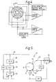
- Figure 4 illustrates a similar device of unitary construction made from piezo-electric material where the drive and pick-up transducers are formed by polarising the material between electrode regions,
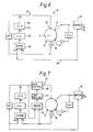
- Figures 5 to 10 illustrates a rate sensor according to various different embodiments of the present invention.
- Referring now to the drawings in general but particularly to Figure 5, a vibrating rate sensor for detecting rotational movement about an axis includes a
cylinder 12 positioned about said axis X, primary andsecondary drive transducers transducers 18, 20fordetecting the presence of vibration induced in saidcylinder 12 and primary andsecondary control loops primary control loop 22 is provided for receiving a signal from the primary pick-off transducer 18 and for maintaining resonance of the structure by generating a 90 degree phase shift between theprimary drive transducer 14 and the primary pick-off transducer 18. Thesecondary control loop 23 is provided for receiving a signal from the secondary pick-off transducer 22 which is indicative of rotation of the structure. This signal is directed to thesecondary drive transducer 16 so as to null it to zero. Theprimary control loop 22 includes a phase locked loop (PLL) having aphase detector 30 configured to operate at quadrature, alow pass filter 32 and a voltage controlledoscillator 34. Thevoltage control oscillator 34 provides an output signal for driving theprimary drive transducer 14 and a 90 degree phase shifted reference signal (ref) for returning to phasedetector 30 to form portion of the phase locked loop. The operation of such primary drive circuits is well known in the art and is therefore not described in further detail herein. It should be noted, however, that in this arrangement a phase detector is implemented from the phase lock loop with a demodulator operated at quadrature. This demodulator plus loop- filter combination is a linear device which will not mix the microphonic baseband signal with the carrier. The arrangement therefore reduces, and may even eliminate, demodulation of the voltage control oscillator by microphonic noise. - Turning now to Figure 6, the reference signal to the primary loop demodulator may also be connected to the reference input of the
output demodulator 26. This would ensure that the output demodulator's phase reference is held at 90 degrees with respect to the primary pick-off signal to within the phase-error accuracy of the voltage control oscillator control loop. This arrangement reduces and possibly eliminates phase errors in the output demodulator which can result in induced drifts. In addition, this arrangement may even eliminate phase noise from the output demodulator reference input which in turn would reduce other noise under vibration source. - In Figure 7 it will be seen that the present invention will benefit from the incorporation of a gain control signal deriving means shown generally at 42 and comprising a
demodulator 44, control at 46 and again controldevice 48. In operation, the gain control signal is derived by demodulating the primary pick-off signal at 90 degrees with respect to the voltage control oscillator output signal. This ensures that microphonic noise does not amplitude modulate the primary drive signal thus further reducing noise in the sensor. Alog-arithmic amplifier 50 may be provided for amplifying a signal B on the primary pick-off transducer 18 prior to said signal being passed to thedemodulator 30 of the phase locked loop. This arrangement would provide increased gain at small signal amplitudes (eg when the phase-locked loop is not locked) and would improve the sensors start-up characteristics. It should be noted, however, care should be taken to ensure that mixing of the microphonic noise with the carrier signal provides a negligible increase of noise under vibration. However, once locked, the increase gain could be switched out of the control loop. - Figure 9 illustrates a further arrangement of the present invention in which a
high pass filter 52 is incorporated into the secondary control circuit. Thehigh pass filter 52 acts to fitter the signal from the secondary pick-off transducer 20 prior to said signal being passed to the secondary loop filter. Failure to provide thehigh pass filter 52 could result in the amplification of microphonic noise by the secondary loop filter and feedback to the cylinder on the secondary drive. In addition to this, the signal is fed to thedemodulator 26 which must then reject the baseband noise. - Referring to Figure 10, the secondary filter may be implemented using a
demodulation stage filter stage modulation stage primary drive transducer 14. This gain stage could be implemented using a transformer. Such an arrangement would ensure that the vibration signal is increased with respect to the measured microphonic noise. - It will of course be appreciated that the
primary drive electrode 14 is preferably optimised in size and shape in order to ensure the maximum drive apply to the cylinder. This would allow an increase in the vibration signal with respect to the measured microphonic noise. For a cos (2 O) mode, the optimum angle attended by the electrode is 45 degrees and the primary drive signal should be applied to the opposite electrode as perthe presently known arrangement. In addition, a primary drive signal which is inverted can be applied to the electrode at 90 degrees to the primary drive electrodes, while the other electrode at 90 degrees is used as a primary pick-off transducer.
Claims (9)
Applications Claiming Priority (2)
| Application Number | Priority Date | Filing Date | Title |
|---|---|---|---|
| GB9207886A GB2266149B (en) | 1992-04-10 | 1992-04-10 | Single axis rate sensor noise reduction |
| GB9207886 | 1992-04-10 |
Publications (2)
| Publication Number | Publication Date |
|---|---|
| EP0565384A1 true EP0565384A1 (en) | 1993-10-13 |
| EP0565384B1 EP0565384B1 (en) | 1997-06-04 |
Family
ID=10713799
Family Applications (1)
| Application Number | Title | Priority Date | Filing Date |
|---|---|---|---|
| EP93302811A Expired - Lifetime EP0565384B1 (en) | 1992-04-10 | 1993-04-08 | Single axis rate sensor noise reduction |
Country Status (5)
| Country | Link |
|---|---|
| US (1) | US5419194A (en) |
| EP (1) | EP0565384B1 (en) |
| JP (1) | JP3064736B2 (en) |
| DE (1) | DE69311196T2 (en) |
| GB (1) | GB2266149B (en) |
Cited By (4)
| Publication number | Priority date | Publication date | Assignee | Title |
|---|---|---|---|---|
| EP1265053A1 (en) * | 2001-06-04 | 2002-12-11 | Kelsey-Hayes Company | Diagnostic test for a resonant micro electro mechanical angular rate system |
| EP2040032A1 (en) | 2007-09-19 | 2009-03-25 | Atlantic Inertial Systems Limited | Improvements in or relating to angular velocity sensors |
| US8347718B2 (en) | 2007-09-18 | 2013-01-08 | Atlantic Inertial Systems Limited | Angular velocity sensors |
| EP3205978A1 (en) | 2016-02-09 | 2017-08-16 | Atlantic Inertial Systems Limited | Inertial sensors |
Families Citing this family (30)
| Publication number | Priority date | Publication date | Assignee | Title |
|---|---|---|---|---|
| JPH06242135A (en) * | 1993-02-12 | 1994-09-02 | Aisin Seiki Co Ltd | Driving circuit for angular velocity sensor |
| JP3453724B2 (en) * | 1994-06-03 | 2003-10-06 | アイシン精機株式会社 | Angular velocity detector |
| JP3479853B2 (en) * | 1994-10-05 | 2003-12-15 | アイシン精機株式会社 | Vibrator drive |
| US5817940A (en) * | 1996-03-14 | 1998-10-06 | Aisin Seiki Kabishiki Kaisha | Angular rate detector |
| FR2749394B1 (en) | 1996-05-29 | 1998-08-07 | Sagem | ROTATION MEASURING APPARATUS |
| JPH10115526A (en) | 1996-10-15 | 1998-05-06 | Ngk Insulators Ltd | Vibration gyro sensor and manufacture of vibration gyro sensor |
| FR2755227B1 (en) * | 1996-10-31 | 1998-12-31 | Sagem | ROTATION MEASURING DEVICE WITH VIBRATING MECHANICAL RESONATOR |
| JP3702607B2 (en) * | 1997-02-28 | 2005-10-05 | 株式会社村田製作所 | Angular velocity detector |
| DE19710359B4 (en) * | 1997-03-13 | 2006-05-11 | Robert Bosch Gmbh | Device for determining a movement quantity with automatic tray factor tracking |
| US5983718A (en) * | 1997-07-14 | 1999-11-16 | Litton Systems, Inc. | Signal processing system for inertial sensor |
| US7051590B1 (en) * | 1999-06-15 | 2006-05-30 | Analog Devices Imi, Inc. | Structure for attenuation or cancellation of quadrature error |
| GB0001294D0 (en) * | 2000-01-20 | 2000-03-08 | British Aerospace | Multi-axis sensing device |
| JP4889849B2 (en) * | 2000-09-27 | 2012-03-07 | オンセミコンダクター・トレーディング・リミテッド | Sine wave generator |
| US6585338B2 (en) | 2000-12-22 | 2003-07-01 | Honeywell International Inc. | Quick start resonant circuit control |
| US7558549B2 (en) * | 2004-02-09 | 2009-07-07 | Broadcom Corporation | Method and system for rejecting single-sided leakage into an amplitude modulated (AM) channel |
| RU2276370C1 (en) * | 2004-10-05 | 2006-05-10 | Открытое акционерное общество "Раменское приборостроительное конструкторское бюро" | Angular speed indicator |
| US20100154542A1 (en) * | 2005-05-31 | 2010-06-24 | Innalabs Technologies, Inc. | Sensing element of coriolis force gyroscope |
| EP2177875A3 (en) * | 2008-10-14 | 2013-04-24 | Watson Industries, Inc. | A Vibrating Structural Gyroscope with Quadrature Control |
| FR2937413B1 (en) * | 2008-10-22 | 2010-11-26 | Sagem Defense Securite | METHOD FOR CONTROLLING A QUICK-START VIBRANT RESONATOR SENSOR |
| JP5708458B2 (en) * | 2011-11-29 | 2015-04-30 | 株式会社デンソー | Angular velocity detector |
| US9146109B2 (en) * | 2012-11-26 | 2015-09-29 | Stmicroelectronics S.R.L. | Microelectromechanical gyroscope with improved start-up phase, system including the microelectromechanical gyroscope, and method for speeding-up the start up phase |
| US9605964B2 (en) * | 2014-01-03 | 2017-03-28 | The Boeing Company | Gyro quadrature stabalization with demodulation phase error nulling |
| US11231441B2 (en) * | 2015-05-15 | 2022-01-25 | Invensense, Inc. | MEMS structure for offset minimization of out-of-plane sensing accelerometers |
| US9952252B2 (en) | 2015-05-15 | 2018-04-24 | Invensense, Inc. | Offset rejection electrodes |
| US10295558B2 (en) | 2015-05-15 | 2019-05-21 | Invensense, Inc. | Offset rejection electrodes |
| GB2560334A (en) * | 2017-03-07 | 2018-09-12 | Atlantic Inertial Systems Ltd | Gyroscope in-field prognostics |
| GB2580116B (en) | 2018-12-21 | 2023-07-19 | Atlantic Inertial Systems Ltd | Gyroscope |
| CN109373991B (en) * | 2018-12-25 | 2023-04-07 | 叶志刚 | Ultrahigh-precision optical fiber gyroscope based on closed-loop phase-locking method |
| EP3985352B1 (en) | 2020-10-16 | 2023-12-27 | Atlantic Inertial Systems Limited | Gyroscope |
| JP7815060B2 (en) * | 2022-08-09 | 2026-02-17 | 株式会社東芝 | Phase locked loop circuit and sensing device |
Citations (3)
| Publication number | Priority date | Publication date | Assignee | Title |
|---|---|---|---|---|
| GB1303237A (en) * | 1970-10-01 | 1973-01-17 | ||
| GB2061502A (en) * | 1979-10-19 | 1981-05-13 | Marconi Co Ltd | A Sensor for Detecting Rotational Movement |
| EP0153189A2 (en) * | 1984-02-22 | 1985-08-28 | National Research Development Corporation | Gyroscopic devices |
Family Cites Families (3)
| Publication number | Priority date | Publication date | Assignee | Title |
|---|---|---|---|---|
| US4996877A (en) * | 1989-02-24 | 1991-03-05 | Litton Systems, Inc. | Three axis inertial measurement unit with counterbalanced mechanical oscillator |
| US5218867A (en) * | 1989-07-29 | 1993-06-15 | British Aerospace Public Limited Company | Single axis attitude sensor |
| DE69102590T2 (en) * | 1990-05-18 | 1994-10-06 | British Aerospace | Inertial sensors. |
-
1992
- 1992-04-10 GB GB9207886A patent/GB2266149B/en not_active Revoked
-
1993
- 1993-04-08 EP EP93302811A patent/EP0565384B1/en not_active Expired - Lifetime
- 1993-04-08 DE DE69311196T patent/DE69311196T2/en not_active Expired - Lifetime
- 1993-04-09 JP JP5083599A patent/JP3064736B2/en not_active Expired - Fee Related
- 1993-04-09 US US08/044,607 patent/US5419194A/en not_active Expired - Lifetime
Patent Citations (3)
| Publication number | Priority date | Publication date | Assignee | Title |
|---|---|---|---|---|
| GB1303237A (en) * | 1970-10-01 | 1973-01-17 | ||
| GB2061502A (en) * | 1979-10-19 | 1981-05-13 | Marconi Co Ltd | A Sensor for Detecting Rotational Movement |
| EP0153189A2 (en) * | 1984-02-22 | 1985-08-28 | National Research Development Corporation | Gyroscopic devices |
Cited By (7)
| Publication number | Priority date | Publication date | Assignee | Title |
|---|---|---|---|---|
| EP1265053A1 (en) * | 2001-06-04 | 2002-12-11 | Kelsey-Hayes Company | Diagnostic test for a resonant micro electro mechanical angular rate system |
| US6792792B2 (en) | 2001-06-04 | 2004-09-21 | Kelsey-Hayes Company | Diagnostic test for a resonant micro electro mechanical system |
| US8347718B2 (en) | 2007-09-18 | 2013-01-08 | Atlantic Inertial Systems Limited | Angular velocity sensors |
| EP2040032A1 (en) | 2007-09-19 | 2009-03-25 | Atlantic Inertial Systems Limited | Improvements in or relating to angular velocity sensors |
| EP3205978A1 (en) | 2016-02-09 | 2017-08-16 | Atlantic Inertial Systems Limited | Inertial sensors |
| GB2547415A (en) * | 2016-02-09 | 2017-08-23 | Atlantic Inertial Systems Ltd | Inertial sensors |
| US10209270B2 (en) | 2016-02-09 | 2019-02-19 | Atlantic Inertial Systems, Limited | Inertial sensors |
Also Published As
| Publication number | Publication date |
|---|---|
| JPH0618545A (en) | 1994-01-25 |
| EP0565384B1 (en) | 1997-06-04 |
| DE69311196D1 (en) | 1997-07-10 |
| GB2266149A (en) | 1993-10-20 |
| GB9207886D0 (en) | 1992-05-27 |
| JP3064736B2 (en) | 2000-07-12 |
| GB2266149B (en) | 1995-08-16 |
| DE69311196T2 (en) | 1997-09-18 |
| US5419194A (en) | 1995-05-30 |
Similar Documents
| Publication | Publication Date | Title |
|---|---|---|
| EP0565384B1 (en) | Single axis rate sensor noise reduction | |
| US5218867A (en) | Single axis attitude sensor | |
| KR101131098B1 (en) | Method for reducing bias error in a vibrating structure gyroscope | |
| KR101437190B1 (en) | A device for measuring the turnover rate using a vibration sensor | |
| US8347718B2 (en) | Angular velocity sensors | |
| JP7115509B2 (en) | Gyroscope continuous self-test | |
| JP3372546B2 (en) | Device for compensating phase rotation in final amplifier stage | |
| US10175307B1 (en) | FM demodulation system for quartz MEMS magnetometer | |
| KR100817802B1 (en) | Control system for vibration structure gyroscope | |
| KR100789049B1 (en) | Method for determining a zero-point error in a vibratory gyroscope | |
| EP1622270B1 (en) | A wide band digital phase locked loop (pll) with a half-frequency output | |
| US6467346B1 (en) | Coriolis sensor interface | |
| EP1417455A2 (en) | Microgyroscope with electronic alignment and tuning | |
| US6230562B1 (en) | Detection circuit for vibratory gyro and vibratory gyro device using the same | |
| EP0567340A1 (en) | Vibrating rate sensor tuning | |
| JP3761111B2 (en) | Angular velocity measuring device and angular velocity measuring method | |
| AU2004227053B2 (en) | Method for determining a zero-point error in a vibratory gyroscope | |
| GB2290144A (en) | Angular rotation rate detector | |
| US5978084A (en) | Open loop signal processing circuit and method for a fiber optic interferometric sensor | |
| US7053534B2 (en) | Piezoelectric vibration gyro-sensor | |
| WO2004105230A1 (en) | Fm signal demodulation method and device thereof | |
| EP0411849B1 (en) | Attitude sensor | |
| US20050092084A1 (en) | Rate sensing device | |
| JP2001289608A (en) | Rotation angle detector | |
| KR20070100862A (en) | Determination of Zero Error in Vibration Gyroscopes |
Legal Events
| Date | Code | Title | Description |
|---|---|---|---|
| PUAI | Public reference made under article 153(3) epc to a published international application that has entered the european phase |
Free format text: ORIGINAL CODE: 0009012 |
|
| 17P | Request for examination filed |
Effective date: 19930419 |
|
| AK | Designated contracting states |
Kind code of ref document: A1 Designated state(s): DE FR GB IT NL SE |
|
| 17Q | First examination report despatched |
Effective date: 19950503 |
|
| GRAG | Despatch of communication of intention to grant |
Free format text: ORIGINAL CODE: EPIDOS AGRA |
|
| GRAH | Despatch of communication of intention to grant a patent |
Free format text: ORIGINAL CODE: EPIDOS IGRA |
|
| GRAH | Despatch of communication of intention to grant a patent |
Free format text: ORIGINAL CODE: EPIDOS IGRA |
|
| ITF | It: translation for a ep patent filed | ||
| GRAA | (expected) grant |
Free format text: ORIGINAL CODE: 0009210 |
|
| AK | Designated contracting states |
Kind code of ref document: B1 Designated state(s): DE FR GB IT NL SE |
|
| PG25 | Lapsed in a contracting state [announced via postgrant information from national office to epo] |
Ref country code: NL Free format text: LAPSE BECAUSE OF FAILURE TO SUBMIT A TRANSLATION OF THE DESCRIPTION OR TO PAY THE FEE WITHIN THE PRESCRIBED TIME-LIMIT Effective date: 19970604 |
|
| REF | Corresponds to: |
Ref document number: 69311196 Country of ref document: DE Date of ref document: 19970710 |
|
| ET | Fr: translation filed | ||
| PG25 | Lapsed in a contracting state [announced via postgrant information from national office to epo] |
Ref country code: SE Effective date: 19970904 |
|
| NLV1 | Nl: lapsed or annulled due to failure to fulfill the requirements of art. 29p and 29m of the patents act | ||
| PLBE | No opposition filed within time limit |
Free format text: ORIGINAL CODE: 0009261 |
|
| STAA | Information on the status of an ep patent application or granted ep patent |
Free format text: STATUS: NO OPPOSITION FILED WITHIN TIME LIMIT |
|
| 26N | No opposition filed | ||
| REG | Reference to a national code |
Ref country code: GB Ref legal event code: IF02 |
|
| REG | Reference to a national code |
Ref country code: GB Ref legal event code: 732E |
|
| REG | Reference to a national code |
Ref country code: FR Ref legal event code: TP |
|
| PGFP | Annual fee paid to national office [announced via postgrant information from national office to epo] |
Ref country code: IT Payment date: 20080329 Year of fee payment: 16 |
|
| PGFP | Annual fee paid to national office [announced via postgrant information from national office to epo] |
Ref country code: GB Payment date: 20100331 Year of fee payment: 18 |
|
| PGFP | Annual fee paid to national office [announced via postgrant information from national office to epo] |
Ref country code: FR Payment date: 20100506 Year of fee payment: 18 |
|
| PGFP | Annual fee paid to national office [announced via postgrant information from national office to epo] |
Ref country code: DE Payment date: 20100423 Year of fee payment: 18 |
|
| PG25 | Lapsed in a contracting state [announced via postgrant information from national office to epo] |
Ref country code: IT Free format text: LAPSE BECAUSE OF NON-PAYMENT OF DUE FEES Effective date: 20090408 |
|
| REG | Reference to a national code |
Ref country code: DE Ref legal event code: R119 Ref document number: 69311196 Country of ref document: DE |
|
| REG | Reference to a national code |
Ref country code: DE Ref legal event code: R119 Ref document number: 69311196 Country of ref document: DE |
|
| GBPC | Gb: european patent ceased through non-payment of renewal fee |
Effective date: 20110408 |
|
| REG | Reference to a national code |
Ref country code: FR Ref legal event code: ST Effective date: 20111230 |
|
| PG25 | Lapsed in a contracting state [announced via postgrant information from national office to epo] |
Ref country code: FR Free format text: LAPSE BECAUSE OF NON-PAYMENT OF DUE FEES Effective date: 20110502 |
|
| PG25 | Lapsed in a contracting state [announced via postgrant information from national office to epo] |
Ref country code: GB Free format text: LAPSE BECAUSE OF NON-PAYMENT OF DUE FEES Effective date: 20110408 |
|
| PG25 | Lapsed in a contracting state [announced via postgrant information from national office to epo] |
Ref country code: DE Free format text: LAPSE BECAUSE OF NON-PAYMENT OF DUE FEES Effective date: 20111031 |