EP0565375B1 - Double-ended arc discharge lamps - Google Patents
Double-ended arc discharge lamps Download PDFInfo
- Publication number
- EP0565375B1 EP0565375B1 EP93302773A EP93302773A EP0565375B1 EP 0565375 B1 EP0565375 B1 EP 0565375B1 EP 93302773 A EP93302773 A EP 93302773A EP 93302773 A EP93302773 A EP 93302773A EP 0565375 B1 EP0565375 B1 EP 0565375B1
- Authority
- EP
- European Patent Office
- Prior art keywords
- shroud
- outer jacket
- arc discharge
- double
- discharge lamp
- Prior art date
- Legal status (The legal status is an assumption and is not a legal conclusion. Google has not performed a legal analysis and makes no representation as to the accuracy of the status listed.)
- Expired - Lifetime
Links
Images

Classifications
-
- H—ELECTRICITY
- H01—ELECTRIC ELEMENTS
- H01J—ELECTRIC DISCHARGE TUBES OR DISCHARGE LAMPS
- H01J61/00—Gas-discharge or vapour-discharge lamps
- H01J61/02—Details
- H01J61/50—Auxiliary parts or solid material within the envelope for reducing risk of explosion upon breakage of the envelope, e.g. for use in mines
-
- H—ELECTRICITY
- H01—ELECTRIC ELEMENTS
- H01J—ELECTRIC DISCHARGE TUBES OR DISCHARGE LAMPS
- H01J61/00—Gas-discharge or vapour-discharge lamps
- H01J61/02—Details
- H01J61/30—Vessels; Containers
- H01J61/34—Double-wall vessels or containers
Definitions
- This invention relates to arc discharge lamps and to a method of making the same and, more particularly, to double-ended metal halide arc discharge lamps which include a light-transmissive shroud.
- the shroud improves lamp performance and acts as a containment device in the event that the arc tube shatters.
- a typical conventional metal halide arc discharge lamp includes a quartz or fused silica arc tube that is hermetically sealed within an outer jacket or envelope.
- the arc tube itself hermetically sealed, has tungsten electrodes mounted therein and contains a fill material including mercury, metal halide additives and a rare gas to facilitate starting.
- the outer envelope is filled with nitrogen or another inert gas at less than atmospheric pressure. In other cases, particularly in low wattage lamps, the outer envelope is evacuated.
- metal halide arc discharge lamps with a shroud which comprises a generally cylindrical light-transmissive member, such as quartz, that is able to withstand high operating temperatures.
- the arc tube and the shroud are coaxially mounted within the lamp envelope with the arc tube located within the shroud.
- the shroud is a tube that is open at both ends. In other cases the shroud is open at one end and has a domed configuration at the other end.
- Shrouds for metal halide arc discharge lamps are disclosed in US-A-4,499,396 issued February 12, 1985 to Fohl et al.; US-A-4,620,125 issued October 28, 1986 to Keeffe et al; US-A-4,625,141 issued November 25, 1986 to Keeffe et al; US-A-4,580,989 issued April 8, 1986 to Fohl et al.; US-A-4,709,184 issued November 24, 1987 to Keeffe et al.; US-A-4,721,876 issued January 26, 1988 to White et al.; US-A-4,791,334 issued December 13, 1988 to Keeffe et al.; US-A-4,888,517 issued December 19, 1989 to Keeffe et al.; and US-A-5,023,505 issued June 11, 1991 to Ratliff et al. See also US-A-4,281,274 issued July 28, 1981 to Bechard et al.
- the shroud has several beneficial effects on lamp operation.
- the shroud reduces convective heat losses from the arc tube and thereby improves the luminous output and the colour temperature of the lamp.
- the shroud helps to equalize the temperature of the arc tube.
- the shroud effectively reduces sodium losses from the arc tube and improves the maintenance of phosphor efficiency in metal halide lamps having a phosphor coating on the inside surface of the outer envelope.
- the shroud improves the safety of the lamp by acting as a containment device in the event that the arc tube shatters.
- Double-ended metal halide lamps have been developed for low wattage and other special applications.
- the arc tube is mounted within a light-transmissive outer jacket and the ends of the outer jacket are press-sealed, with the arc tube electrical leads extending through the press seals.
- the lamp is mechanically supported at both ends, and electrical energy is applied to opposite ends of the lamp.
- the shroud mounting techniques used in prior art single-ended lamps may not be suitable for use in double-ended lamps.
- the space between the outer jacket and the arc tube is very limited.
- these lamps operate at high temperatures. There may be insufficient space to mount the shroud using a metal frame and clips or straps. Even if metal mounting elements could be utilized, it is likely that they would be subject to fatigue in the high operating temperatures of double-ended metal halide lamps.
- the present invention is characterised in that the shroud is open at both ends.
- the shroud may be supported by the outer jacket at any convenient location or plurality of locations along its length.
- the shroud may be supported substantially along its entire length or at one or a plurality of end, central or intermediate locations.
- the shroud is supported adjacent its ends.
- the shroud includes one or more radially outwardly extending portions supported by the outer jacket.
- the shroud may have one or more axially extending ribs, flared portions or one or a series of circumferentially spaced lugs.
- the shroud has radially outwardly extending flanges formed at each end.
- the shroud may also be supported by one or more radially inwardly extending portions such as flanges, lugs or ribs formed on the outer jacket, preferably adjacent the ends of the shroud.
- the outer jacket includes reduced diameter portions near each end which support the shroud.
- Inwardly and outwardly extending portions on the outer jacket and on the shroud may act to space the shroud from the outer jacket.
- the shroud may be supported by separate spacer means located between the shroud and the outer jacket.
- locating means are provided for locating the shroud with respect to the outer jacket.
- such locating means preferably locates the shroud at least axially with respect to the outer jacket.
- one or more radially outwardly extending portions on the shroud may cooperate with one or more inwardly extending portions on the outer jacket to prevent the shroud sliding axially with respect to the jacket.
- one or more inwardly extending dimples are provided on the jacket to locate one or more flanges on the shroud.
- the shroud is affixed to the outer jacket such as by fusing.
- a radially outwardly extending portion on the shroud is affixed to the outer jacket and/or a radially inwardly extending portion on the outer jacket is affixed to the shroud.
- the space between the outer jacket and the shroud is preferably interconnected with the interior of the shroud. This permits the space between the outer jacket and the shroud to be cleaned after processing and also ensures equalization of pressures on the inner and outer surfaces of the shroud during operation.
- An opening may be formed directly between the interior of the shroud and the space between the shroud and the jacket, for example a radial opening in preferred arrangements having a generally circular-cylindrical shroud and outer jacket.
- the interior of the shroud and the space between the shroud and the outer jacket both communicate with a region of the outer jacket outside of said space and thereby communicate with each other.
- this region will generally lie to one or both ends of the shroud.
- the shroud is open at one or at both ends.
- Communication between the outer jacket generally and the space between the shroud and the outer jacket may be provided by an opening in a radially outwardly extending portion of the shroud or in radially inwardly extending portion of the jacket.
- openings will exist in any event, for example where the shroud is supported by circumferentially spaced lugs or ribs.
- openings into the space between the shroud and the jacket may be provided for example by apertures formed in said flanges or flared portions or by notches or flats formed thereon.
- the present invention provides a method of making a double-ended arc discharge lamp, comprising the steps of:
- a shroud having outwardly extending end portions for spacing the shroud from the outer jacket and for supporting the shroud within the outer jacket is positioned within the outer jacket, and the end portions of the shroud are attached to the outer jacket.
- FIGS. 1 and 2 A double-ended metal halide arc discharge lamp in accordance with one embodiment of the present invention is shown in FIGS. 1 and 2.
- An arc tube 10 is sealed within an outer jacket 12.
- the outer jacket 12 is hermetically sealed by press seals 14 and 16 at opposite ends. Press sealing techniques are well known in the art.
- Electrical leads 20 and 22 extend from opposite ends of arc tube 10 through press seals 14 and 16 to external electrical contacts 24 and 26, respectively.
- a light-transmissive shroud 30 is located between the arc tube 10 and outer jacket 12.
- a getter 32 is attached to electrical lead 22.
- the arc tube 10 can be a metal halide arc discharge tube, a tungsten halogen lamp capsule, or any other lamp capsule that is advantageously utilized in a double-ended configuration with a shroud.
- a quartz arc tube has electrodes mounted within and contains a fill material including mercury, metal halide additives and a rare gas to facilitate starting. The electrodes are electrically connected through press seals to leads 20 and 22. Techniques for making metal halide arc tubes are well known in the art.
- the outer jacket 12 is preferably light-transmissive quartz and has a tubular shape, except in the regions of press seals 14 and 16.
- the shroud 30 is typically a cylindrical quartz tube and is supported at its ends by the outer jacket 12.
- the shroud 30 has a wall thickness in a range of about 0.75 mm to 1.5 mm.
- the shroud 30 includes outwardly extending flanges 40 and 42 at its ends. The flanges 40 and 42 are attached to the inner surface of outer jacket 12.
- the shroud 30 is supported directly by outer jacket 12 and is centered within and spaced from outer jacket 12.
- the shroud 30 surrounds the arc tube 10 and functions as a containment means to minimize the risk of breakage of the outer jacket 12 upon rupture of the arc tube 10, which operates at positive pressures.
- the shroud 30 also acts as an infrared radiation shield, thereby reducing heat loss and improving operating efficiency.
- the shroud redistributes heat returned to the arc tube to obtain a more uniform wall temperature distribution, thereby allowing a higher cold spot temperature and improving the spectral characteristics of the lamp.
- Such shrouds are further known to retain an electrical charge, when suitably electrically isolated, to retard sodium loss from arc tube 10 and to improve color constancy and voltage rise over lamp life.
- the shroud 30 in the lamp of FIGS. 1 and 2 is electrically isolated from any of the electrical components of the lamp.
- the shroud 30 is made by forming flanges at the ends of a cut quartz tube to the inside diameter of the outer jacket 12.
- the flanges 40 and 42 are formed by heating the ends of the quartz tube and shaping them to the proper diameter.
- the outer diameters of the flanges 40 and 42 are equal to or slightly less than the inside diameter of the outer jacket 12 and are concentric with the axis of shroud 30.
- the shroud 30 with flanges 40 and 42 is slid into the tubular outer jacket 12 and is fixed in a desired position by fusing flanges 40 and 42 to outer jacket 12.
- the outer jacket 12 and the shroud 30 form a lamp envelope assembly 46.
- the arc tube 10 is then sealed within the lamp envelope assembly 46 using conventional press-sealing techniques to obtain a finished lamp as shown in FIGS. 1 and 2.
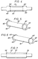
- FIG. 4 A simplified schematic diagram of an alternative or additional technique for locating the shroud 30 within the outer jacket 12 is shown in FIG. 4.
- the arc tube is omitted from FIG. 4.
- the outer jacket 12 is provided with inwardly-extending dimples 50 and 52 which retain flanges 40 and 42, respectively, thereby locating the shroud 30 with respect to outer jacket 12.
- the dimples are located adjacent to each end of the shroud 30.
- the dimples 50 and 52 can be used as an alternative to, or in addition to, fusing of flanges 40 and 42 to outer jacket 12.
- FIG. 5 A preferred embodiment of the shroud 30 is shown in FIG. 5.
- flanges 40 and 42 extend outwardly from the cylindrical portion of shroud 30 and have outside diameters that are equal to or slightly less than the inside diameter of outer jacket 12. The difference between the outside diameter of the cylinder portion of shroud 30 and the outside diameter of flanges 40 and 42 establishes a spacing between shroud 30 and outer jacket 12.
- the flanges 40 and 42 are preferably provided with notches 60.
- the notches 60 define passages that interconnect the interior of shroud 30 to an annular space between the shroud 30 and outer jacket 12.
- the passages defined by notches 60 permit gas or liquid to flow into and out of the space between the shroud 30 and the outer jacket 12.
- a cleaning fluid can be circulated through the annular space between shroud 30 and outer jacket 12 to remove smoke and other contaminants that were deposited during the assembly process.
- the passages defined by notches 60 ensure that the pressure is equalized on the inside and outside surfaces of shroud 30.
- FIG. 6 An alternative embodiment of the shroud 30 is shown in FIG. 6.
- the flanges 40 and 42 are provided with cutaway portions 62.
- the cutaway portions 62 define passages for access to the annular space between shroud 30 and outer jacket 12.
- the outer jacket had an outside diameter of 25 mm, an inside diameter of 22 mm and an overall length of 108 mm.
- the shroud had an outside diameter of 20 mm, an inside diameter of 18 mm and a length of 45 mm.
- the shroud and the outer jacket were fabricated of quartz.
- a metal halide arc tube rated at 150 watts was used.
- the outer jacket had an outside diameter of 20 mm, an inside diameter of 18 mm and an overall length of 107 mm.
- the shroud had an outside diameter of 14 mm, an inside diameter of 12 mm and a length of 35 mm.
- a metal halide arc tube rated at 40 watts was used.
- FIG. 7 A schematic diagram of another embodiment of the present invention is shown in FIG. 7.
- a cylindrical shroud 70 is mounted within an outer jacket 72.
- the arc tube is omitted from FIG. 7 for simplicity.
- the shroud 70 does not include flanges as described above. Instead, the outer jacket 72 is reduced in diameter at regions 74 and 75 near its ends and is attached to the respective ends of shroud 70, typically by fusing.
- the embodiment shown in FIG. 7 produces relatively thick quartz in the regions where the outer jacket 72 is fused to shroud 70 and makes press sealing of the outer jacket 72 somewhat more difficult. However, assuming that the outer jacket can be sealed satisfactorily, the configuration of FIG. 7 is acceptable.
- the double-ended arc discharge lamp structure shown and described herein permits mounting of a shroud that is electrically isolated from the leads of the lamp and is mounted without the use of metal clamps and frames.
- the outer jacket is protected by the shroud in the event that the arc tube ruptures. Since the shroud is electrically isolated, the effect on sodium loss is minimized.
- the disclosed lamp configuration provides containment strength, shock and vibration resistance, compact physical dimensions and the ability to withstand high operating temperatures.
Landscapes
- Vessels And Coating Films For Discharge Lamps (AREA)
Description
- This invention relates to arc discharge lamps and to a method of making the same and, more particularly, to double-ended metal halide arc discharge lamps which include a light-transmissive shroud. The shroud improves lamp performance and acts as a containment device in the event that the arc tube shatters.
- Conventional metal halide arc discharge lamps are frequently employed in commercial usage because of their high luminous efficacy and long life. A typical conventional metal halide arc discharge lamp includes a quartz or fused silica arc tube that is hermetically sealed within an outer jacket or envelope. The arc tube, itself hermetically sealed, has tungsten electrodes mounted therein and contains a fill material including mercury, metal halide additives and a rare gas to facilitate starting. In some cases, particularly in high wattage lamps, the outer envelope is filled with nitrogen or another inert gas at less than atmospheric pressure. In other cases, particularly in low wattage lamps, the outer envelope is evacuated.
- It has been found desirable to provide metal halide arc discharge lamps with a shroud which comprises a generally cylindrical light-transmissive member, such as quartz, that is able to withstand high operating temperatures. The arc tube and the shroud are coaxially mounted within the lamp envelope with the arc tube located within the shroud. Preferably, the shroud is a tube that is open at both ends. In other cases the shroud is open at one end and has a domed configuration at the other end. Shrouds for metal halide arc discharge lamps are disclosed in US-A-4,499,396 issued February 12, 1985 to Fohl et al.; US-A-4,620,125 issued October 28, 1986 to Keeffe et al; US-A-4,625,141 issued November 25, 1986 to Keeffe et al; US-A-4,580,989 issued April 8, 1986 to Fohl et al.; US-A-4,709,184 issued November 24, 1987 to Keeffe et al.; US-A-4,721,876 issued January 26, 1988 to White et al.; US-A-4,791,334 issued December 13, 1988 to Keeffe et al.; US-A-4,888,517 issued December 19, 1989 to Keeffe et al.; and US-A-5,023,505 issued June 11, 1991 to Ratliff et al. See also US-A-4,281,274 issued July 28, 1981 to Bechard et al.
- The shroud has several beneficial effects on lamp operation. In lamps with a gas-filled outer envelope, the shroud reduces convective heat losses from the arc tube and thereby improves the luminous output and the colour temperature of the lamp. In lamps with an evacuated outer envelope, the shroud helps to equalize the temperature of the arc tube. In addition, the shroud effectively reduces sodium losses from the arc tube and improves the maintenance of phosphor efficiency in metal halide lamps having a phosphor coating on the inside surface of the outer envelope. Finally, the shroud improves the safety of the lamp by acting as a containment device in the event that the arc tube shatters.
- Many of the known prior art metal halide lamps which utilize a shroud are single-ended with respect to mounting and application of electrical energy to the arc tube. The shroud is held in position within the lamp envelope by attaching it to a metal frame which extends between the ends of the lamp envelope. Metal clips or straps attached to the ends of the shroud are welded to the frame.
- Double-ended metal halide lamps have been developed for low wattage and other special applications. In a typical arrangement the arc tube is mounted within a light-transmissive outer jacket and the ends of the outer jacket are press-sealed, with the arc tube electrical leads extending through the press seals. The lamp is mechanically supported at both ends, and electrical energy is applied to opposite ends of the lamp. It is now considered desirable to use a light-transmissive shroud in a double-ended metal halide lamp to provide one or more of the advantages described above. However, the shroud mounting techniques used in prior art single-ended lamps may not be suitable for use in double-ended lamps. In double-ended lamps, the space between the outer jacket and the arc tube is very limited. In addition, these lamps operate at high temperatures. There may be insufficient space to mount the shroud using a metal frame and clips or straps. Even if metal mounting elements could be utilized, it is likely that they would be subject to fatigue in the high operating temperatures of double-ended metal halide lamps.
- A number of double-ended arc discharge lamp arrangements are disclosed in US-A-3,619,682, JP-A-58,225555 and US-A-2,056,633. It is known from US-A-2,056,633 to provide a double-ended arc discharge lamp comprising:
- a sealed, tubular light-transmissive outer jacket;
- an arc discharge tube disposed within said outer jacket;
- means for coupling electrical energy through opposite ends of said outer jacket to said arc discharge tube; and
- a tubular light-transmissive shroud being disposed between said outer jacket and said arc discharge tube and being directly supported by said outer jacket.
- The present invention is characterised in that the shroud is open at both ends.
- The shroud may be supported by the outer jacket at any convenient location or plurality of locations along its length. For example the shroud may be supported substantially along its entire length or at one or a plurality of end, central or intermediate locations. Preferably the shroud is supported adjacent its ends.
- In preferred embodiments the shroud includes one or more radially outwardly extending portions supported by the outer jacket. For example, the shroud may have one or more axially extending ribs, flared portions or one or a series of circumferentially spaced lugs. In a preferred arrangement the shroud has radially outwardly extending flanges formed at each end.
- The shroud may also be supported by one or more radially inwardly extending portions such as flanges, lugs or ribs formed on the outer jacket, preferably adjacent the ends of the shroud. In one embodiment the outer jacket includes reduced diameter portions near each end which support the shroud.
- Inwardly and outwardly extending portions on the outer jacket and on the shroud may act to space the shroud from the outer jacket. The shroud may be supported by separate spacer means located between the shroud and the outer jacket.
- Preferably means are provided for locating the shroud with respect to the outer jacket. In the case of a tubular shroud such locating means preferably locates the shroud at least axially with respect to the outer jacket. For example, one or more radially outwardly extending portions on the shroud may cooperate with one or more inwardly extending portions on the outer jacket to prevent the shroud sliding axially with respect to the jacket. In a preferred arrangement one or more inwardly extending dimples are provided on the jacket to locate one or more flanges on the shroud.
- In preferred arrangements the shroud is affixed to the outer jacket such as by fusing. Conveniently a radially outwardly extending portion on the shroud is affixed to the outer jacket and/or a radially inwardly extending portion on the outer jacket is affixed to the shroud.
- The space between the outer jacket and the shroud is preferably interconnected with the interior of the shroud. This permits the space between the outer jacket and the shroud to be cleaned after processing and also ensures equalization of pressures on the inner and outer surfaces of the shroud during operation.
- An opening may be formed directly between the interior of the shroud and the space between the shroud and the jacket, for example a radial opening in preferred arrangements having a generally circular-cylindrical shroud and outer jacket. However, preferably the interior of the shroud and the space between the shroud and the outer jacket both communicate with a region of the outer jacket outside of said space and thereby communicate with each other. In preferred embodiments having a tubular shroud, this region will generally lie to one or both ends of the shroud. Preferably the shroud is open at one or at both ends. Communication between the outer jacket generally and the space between the shroud and the outer jacket may be provided by an opening in a radially outwardly extending portion of the shroud or in radially inwardly extending portion of the jacket. In some arrangements which have already been described such openings will exist in any event, for example where the shroud is supported by circumferentially spaced lugs or ribs. In embodiments wherein flanges or flared portions are provided on the shroud, openings into the space between the shroud and the jacket may be provided for example by apertures formed in said flanges or flared portions or by notches or flats formed thereon.
- Viewed from another aspect, the present invention provides a method of making a double-ended arc discharge lamp, comprising the steps of:
- positioning a tubular light-transmissive shroud, which is open at both ends, within a light-transmissive outer jacket;
- supporting said shroud directly by said outer jacket to form an envelope assembly;
- positioning an arc discharge tube within the envelope assembly; and
- sealing the envelope assembly.
- In a preferred embodiment of this method, a shroud having outwardly extending end portions for spacing the shroud from the outer jacket and for supporting the shroud within the outer jacket is positioned within the outer jacket, and the end portions of the shroud are attached to the outer jacket.
- Embodiments of the invention will now be described, by way of example only, with reference to the accompanying drawings, wherein:
- FIG. 1 is a plan view of a double-ended metal halide arc discharge lamp in accordance with one embodiment of the present invention;
- FIG. 2 is an elevation view of the arc discharge lamp of FIG. 1;
- FIG. 3 is a plan view of a lamp envelope assembly including an outer jacket and a shroud;
- FIG. 4 is a schematic diagram of a double-ended arc discharge lamp wherein the outer jacket is provided with locating dimples, with the arc tube omitted for simplicity;
- FIG. 5 is a perspective view of a shroud having flanges at its ends provided with notches;
- FIG. 6 is a perspective view of a shroud having flanges at its ends with cutaway portions; and
- FIG. 7 is a schematic diagram of another embodiment of the invention, with the arc tube omitted for simplicity.
- A double-ended metal halide arc discharge lamp in accordance with one embodiment of the present invention is shown in FIGS. 1 and 2. An
arc tube 10 is sealed within anouter jacket 12. Theouter jacket 12 is hermetically sealed bypress seals arc tube 10 through press seals 14 and 16 to externalelectrical contacts transmissive shroud 30 is located between thearc tube 10 andouter jacket 12. Agetter 32 is attached toelectrical lead 22. - The
arc tube 10 can be a metal halide arc discharge tube, a tungsten halogen lamp capsule, or any other lamp capsule that is advantageously utilized in a double-ended configuration with a shroud. When the arc tube is a metal halide arc tube, a quartz arc tube has electrodes mounted within and contains a fill material including mercury, metal halide additives and a rare gas to facilitate starting. The electrodes are electrically connected through press seals toleads - The
outer jacket 12 is preferably light-transmissive quartz and has a tubular shape, except in the regions of press seals 14 and 16. Theshroud 30 is typically a cylindrical quartz tube and is supported at its ends by theouter jacket 12. Preferably, theshroud 30 has a wall thickness in a range of about 0.75 mm to 1.5 mm. In the embodiment of FIG. 1 and 2, theshroud 30 includes outwardly extendingflanges flanges outer jacket 12. Thus, theshroud 30 is supported directly byouter jacket 12 and is centered within and spaced fromouter jacket 12. - The
shroud 30 surrounds thearc tube 10 and functions as a containment means to minimize the risk of breakage of theouter jacket 12 upon rupture of thearc tube 10, which operates at positive pressures. Theshroud 30 also acts as an infrared radiation shield, thereby reducing heat loss and improving operating efficiency. In addition, the shroud redistributes heat returned to the arc tube to obtain a more uniform wall temperature distribution, thereby allowing a higher cold spot temperature and improving the spectral characteristics of the lamp. Such shrouds are further known to retain an electrical charge, when suitably electrically isolated, to retard sodium loss fromarc tube 10 and to improve color constancy and voltage rise over lamp life. Theshroud 30 in the lamp of FIGS. 1 and 2 is electrically isolated from any of the electrical components of the lamp. - The
shroud 30 is made by forming flanges at the ends of a cut quartz tube to the inside diameter of theouter jacket 12. Theflanges flanges outer jacket 12 and are concentric with the axis ofshroud 30. Theshroud 30 withflanges outer jacket 12 and is fixed in a desired position by fusingflanges outer jacket 12. As shown in FIG. 3, theouter jacket 12 and theshroud 30 form alamp envelope assembly 46. Thearc tube 10 is then sealed within thelamp envelope assembly 46 using conventional press-sealing techniques to obtain a finished lamp as shown in FIGS. 1 and 2. - A simplified schematic diagram of an alternative or additional technique for locating the
shroud 30 within theouter jacket 12 is shown in FIG. 4. The arc tube is omitted from FIG. 4. Theouter jacket 12 is provided with inwardly-extendingdimples 50 and 52 which retainflanges shroud 30 with respect toouter jacket 12. The dimples are located adjacent to each end of theshroud 30. Thedimples 50 and 52 can be used as an alternative to, or in addition to, fusing offlanges outer jacket 12. - A preferred embodiment of the
shroud 30 is shown in FIG. 5. As noted above,flanges shroud 30 and have outside diameters that are equal to or slightly less than the inside diameter ofouter jacket 12. The difference between the outside diameter of the cylinder portion ofshroud 30 and the outside diameter offlanges shroud 30 andouter jacket 12. - The
flanges notches 60. When theshroud 30 is mounted withinouter jacket 12, thenotches 60 define passages that interconnect the interior ofshroud 30 to an annular space between theshroud 30 andouter jacket 12. The passages defined bynotches 60 permit gas or liquid to flow into and out of the space between theshroud 30 and theouter jacket 12. During assembly, a cleaning fluid can be circulated through the annular space betweenshroud 30 andouter jacket 12 to remove smoke and other contaminants that were deposited during the assembly process. During operation of the lamp, the passages defined bynotches 60 ensure that the pressure is equalized on the inside and outside surfaces ofshroud 30. - An alternative embodiment of the
shroud 30 is shown in FIG. 6. Theflanges cutaway portions 62. When theshroud 30 is mounted in theouter jacket 12, thecutaway portions 62 define passages for access to the annular space betweenshroud 30 andouter jacket 12. - In one example of a double-ended metal halide arc discharge lamp in accordance with the present invention, the outer jacket had an outside diameter of 25 mm, an inside diameter of 22 mm and an overall length of 108 mm. The shroud had an outside diameter of 20 mm, an inside diameter of 18 mm and a length of 45 mm. The shroud and the outer jacket were fabricated of quartz. A metal halide arc tube rated at 150 watts was used.
- In a second example, the outer jacket had an outside diameter of 20 mm, an inside diameter of 18 mm and an overall length of 107 mm. The shroud had an outside diameter of 14 mm, an inside diameter of 12 mm and a length of 35 mm. A metal halide arc tube rated at 40 watts was used.
- A schematic diagram of another embodiment of the present invention is shown in FIG. 7. In the embodiment of FIG. 7, a cylindrical shroud 70 is mounted within an outer jacket 72. The arc tube is omitted from FIG. 7 for simplicity. The shroud 70 does not include flanges as described above. Instead, the outer jacket 72 is reduced in diameter at
regions - The double-ended arc discharge lamp structure shown and described herein permits mounting of a shroud that is electrically isolated from the leads of the lamp and is mounted without the use of metal clamps and frames. The outer jacket is protected by the shroud in the event that the arc tube ruptures. Since the shroud is electrically isolated, the effect on sodium loss is minimized. The disclosed lamp configuration provides containment strength, shock and vibration resistance, compact physical dimensions and the ability to withstand high operating temperatures.
- Thus, in the preferred embodiments there is provided an improved double-ended metal halide arc discharge lamp having the following advantages:-
- (a) the lamp can be safely operated without a protective fixture;
- (b) the lamp has a high luminous output and a long operating life;
- (c) the lamp is small in physical size; and
- (d) the lamp is low in cost and is easily manufactured.
- While there have been shown and described certain embodiments of the present invention, it will be obvious to those skilled in the art that various changes and modifications may be made therein without departing from the scope of the invention as claimed.
- Whilst in the embodiments which have been described herein electrical energy is coupled to the arc discharge tube by means of wires, it will be understood that other means of coupling electrical energy can also be used such as microwave coupling as described for example in US-A-5,070,277 and US-A-5,113,121.
Claims (11)
- A double-ended arc discharge lamp comprising:a sealed, tubular light-transmissive outer jacket (12,72);an arc discharge tube (10) disposed within said outer jacket (12,72); andmeans (20,22) for coupling electrical energy through opposite ends of said outer jacket (12,72) to said arc discharge tube (10);a tubular light-transmissive shroud (30,70), which is open at both ends, being disposed between said outer jacket (12,72) and said arc discharge tube (10) and directly supported by said outer jacket (12,72).
- A double-ended arc discharge lamp as claimed in claim 1, characterised in that said shroud (30) includes at least one radially outwardly extending portion (40,42) spacing said shroud (30) from said outer jacket (12) and supporting said shroud (30) within said outer jacket (12).
- A double-ended arc discharge lamp as claimed in claim 1 or 2, characterised in that the or each radially outwardly extending portion (40,42) is affixed to said outer jacket (12).
- A double-ended arc discharge lamp as claimed in claim 1, 2 or 3, characterised in that the outer jacket (12) has at least one radially inwardly directed protrusion (50,52) to cooperate with a respective radially outwardly extending portion (40,42) of the shroud (30), so as to locate the shroud (30) axially with respect to the jacket (12).
- A double-ended arc discharge lamp as claimed in any preceding claim, characterised in that the shroud (30, 70) is supported by means (40,42;74,75) adjacent each end.
- A double-ended arc discharge lamp as claimed in claim 5, characterised in that the outer jacket (72) has radially inwardly directed portions (74,75) adjacent each end which support the ends of the shroud (70).
- A double-ended arc discharge lamp as claimed in any preceding claim, characterised in that there is fluid communication between the interior of the shroud (30,70) and a space between the shroud (30,70) and the outer jacket (12,72).
- A double-ended arc discharge lamp as claimed in any preceding claim, characterised in that the shroud (30) has a radially outwardly extending portion (40,42) at each end to space the shroud (30) from the outer jacket (12) and support it within the outer jacket (12), and at least one of the outwardly extending portions (40,42) is configured to permit fluid flow into and out of the space between the shroud (30) and the jacket (12), whereby there is fluid communication between the interior of the shroud (30) and the space between the shroud (30) and the outer jacket (12).
- A double-ended arc discharge lamp as claimed in any preceding claim, characterised in that said shroud (30,70) has a wall thickness in a range of about 0.75 mm to 1.5 mm.
- A double-ended arc discharge lamp as claimed in any preceding claim, characterised in that said arc discharge tube (10) comprises a metal halide arc tube.
- A method of making a double-ended arc discharge lamp, comprising the steps of:positioning a tubular light-transmissive shroud (30, 70), which is open at both ends, within a light-transmissive outer jacket (12,72);supporting said shroud (30,70) directly by said outer jacket (12,72) to form an envelope assembly;positioning an arc discharge tube (10) within the envelope assembly; andsealing the envelope assembly.
Applications Claiming Priority (2)
| Application Number | Priority Date | Filing Date | Title |
|---|---|---|---|
| US07/866,381 US5296779A (en) | 1992-04-10 | 1992-04-10 | Double-ended metal halide arc discharge lamp with electrically isolated containment shroud |
| US866381 | 2001-05-25 |
Publications (2)
| Publication Number | Publication Date |
|---|---|
| EP0565375A1 EP0565375A1 (en) | 1993-10-13 |
| EP0565375B1 true EP0565375B1 (en) | 1997-07-09 |
Family
ID=25347489
Family Applications (1)
| Application Number | Title | Priority Date | Filing Date |
|---|---|---|---|
| EP93302773A Expired - Lifetime EP0565375B1 (en) | 1992-04-10 | 1993-04-08 | Double-ended arc discharge lamps |
Country Status (4)
| Country | Link |
|---|---|
| US (2) | US5296779A (en) |
| EP (1) | EP0565375B1 (en) |
| CA (1) | CA2093562A1 (en) |
| DE (1) | DE69311947T2 (en) |
Families Citing this family (10)
| Publication number | Priority date | Publication date | Assignee | Title |
|---|---|---|---|---|
| US5466988A (en) * | 1992-05-11 | 1995-11-14 | Matsushita Electric Industrial Co., Ltd. | High pressure discharge lamp having improved convection regulating means |
| US5610469A (en) * | 1995-03-16 | 1997-03-11 | General Electric Company | Electric lamp with ellipsoidal shroud |
| US6656127B1 (en) * | 1999-06-08 | 2003-12-02 | Oridion Breathid Ltd. | Breath test apparatus and methods |
| US6741013B2 (en) | 2000-12-13 | 2004-05-25 | General Electric Company | Shrouded electric lamp having functionally distinguishable center supports |
| WO2006001166A1 (en) * | 2004-06-29 | 2006-01-05 | Matsushita Electric Industrial Co., Ltd. | Metal halide lamp and lighting apparatus using the same |
| US7375456B2 (en) * | 2005-03-31 | 2008-05-20 | Osram Sylvania Inc. | Mount for high intensity discharge lamp |
| CN102422378A (en) * | 2009-05-15 | 2012-04-18 | 赵正烈 | Double-type external electrode fluorescent lamp and manufacturing method thereof |
| SG11202000286WA (en) | 2016-01-18 | 2020-02-27 | Xenex Disinfection Services Llc | Smoke detector shields and related methods |
| SG11202001809SA (en) | 2016-03-04 | 2020-03-30 | Xenex Disinfection Services Inc | Smoke detectors with light shields and alarm systems including such |
| JP6748680B2 (en) * | 2018-08-31 | 2020-09-02 | 大電株式会社 | Lighting equipment |
Family Cites Families (17)
| Publication number | Priority date | Publication date | Assignee | Title |
|---|---|---|---|---|
| NL37300C (en) * | 1933-06-27 | |||
| FR785633A (en) * | 1934-03-08 | 1935-08-14 | Osa Participations Ind | Luminescent electric tube surrounded by a double-walled heat-insulating vessel |
| US3619682A (en) * | 1969-04-01 | 1971-11-09 | Sylvania Electric Prod | Arc discharge lamp including means for cooling envelope surrounding an arc tube |
| US4281274A (en) * | 1979-08-01 | 1981-07-28 | General Electric Co. | Discharge lamp having vitreous shield |
| DE3129329A1 (en) * | 1981-07-24 | 1983-02-10 | Patent-Treuhand-Gesellschaft für elektrische Glühlampen mbH, 8000 München | SODIUM STEAM HIGH PRESSURE DISCHARGE LAMP |
| US4499396A (en) * | 1982-08-18 | 1985-02-12 | Gte Products Corporation | Metal halide arc discharge lamp with means for suppressing convection currents within the outer envelope and methods of operating same |
| US4580989A (en) * | 1982-08-18 | 1986-04-08 | Gte Products Corporation | Metal halide arc discharge lamp with means for suppressing convection currents within the outer envelope and methods of operating and constructing same |
| US4721876A (en) * | 1982-09-23 | 1988-01-26 | Gte Products Corporation | Light-source capsule containment device and lamp employing such device |
| JPS59194339A (en) * | 1983-04-18 | 1984-11-05 | Mitsubishi Electric Corp | Metallic vapor electric-discharge lamp |
| US4709184A (en) * | 1984-08-20 | 1987-11-24 | Gte Products Corporation | Low wattage metal halide lamp |
| US4620125A (en) * | 1984-10-29 | 1986-10-28 | Gte Products Corporation | Low wattage metal halide lamp with inverted domed sleeve |
| US4625141A (en) * | 1984-10-29 | 1986-11-25 | Gte Products Corporation | Low wattage metal halide discharge lamp electrically biased to reduce sodium loss |
| US4791334A (en) * | 1987-05-07 | 1988-12-13 | Gte Products Corporation | Metal-halide lamp having heat redistribution means |
| US4888517A (en) * | 1987-08-28 | 1989-12-19 | Gte Products Corporation | Double-enveloped lamp having a shield surrounding a light-source capsule within a thick-walled outer envelope |
| US5021703A (en) * | 1989-06-06 | 1991-06-04 | Gte Products Corporation | Metal halide lamp |
| US5023505A (en) * | 1989-12-20 | 1991-06-11 | Gte Products Corporation | Electric lamp with improved frame support and method of producing same |
| US5043623A (en) * | 1990-12-06 | 1991-08-27 | Gte Products Corporation | Reflector lamp assembly including metal halide arc tube |
-
1992
- 1992-04-10 US US07/866,381 patent/US5296779A/en not_active Expired - Fee Related
-
1993
- 1993-04-07 CA CA002093562A patent/CA2093562A1/en not_active Abandoned
- 1993-04-08 DE DE69311947T patent/DE69311947T2/en not_active Expired - Fee Related
- 1993-04-08 EP EP93302773A patent/EP0565375B1/en not_active Expired - Lifetime
- 1993-12-20 US US08/169,698 patent/US5340346A/en not_active Expired - Lifetime
Also Published As
| Publication number | Publication date |
|---|---|
| EP0565375A1 (en) | 1993-10-13 |
| US5296779A (en) | 1994-03-22 |
| US5340346A (en) | 1994-08-23 |
| CA2093562A1 (en) | 1993-10-11 |
| DE69311947D1 (en) | 1997-08-14 |
| DE69311947T2 (en) | 1998-02-05 |
Similar Documents
| Publication | Publication Date | Title |
|---|---|---|
| US5493167A (en) | Lamp assembly with shroud employing insulator support stops | |
| US5252885A (en) | Metal halide arc discharge lamp assembly | |
| US6741013B2 (en) | Shrouded electric lamp having functionally distinguishable center supports | |
| US5136204A (en) | Metal halide arc discharge lamp assembly | |
| US6249077B1 (en) | Arc tube, mounting member and electric lamp assembly | |
| EP0581423B1 (en) | Universal burn metal halide lamp | |
| EP0560936B1 (en) | Reflector lamp assembly including metal halide arc tube | |
| EP0565375A1 (en) | Double-ended arc discharge lamps | |
| US5023506A (en) | Explosion proof high pressure discharge lamp | |
| EP0645800B1 (en) | High pressure discharge lamp | |
| EP0540019B1 (en) | Metal halide arc discharge lamp assembly | |
| EP1046189B1 (en) | Metal halide lamp with stem mounted support frame for arc tube shield | |
| US5075588A (en) | Arc discharge lamp with spring-mounted arc tube and shroud | |
| EP0762478B1 (en) | Lamp with glass sleeve and method of making same | |
| US5859492A (en) | Electrode rod support for short arc lamp | |
| EP0180199B1 (en) | Low wattage metal halide discharge lamp | |
| EP0165587B1 (en) | Metal halide discharge lamp with arc tube temperature equalizing means | |
| US4433271A (en) | High pressure discharge lamp | |
| WO2000075958A1 (en) | Metal halide lamp with protective sleeve | |
| EP1057211B1 (en) | Electric lamp | |
| WO1991018413A1 (en) | Arc discharge lamp having reduced sodium loss | |
| EP0596676B1 (en) | High-pressure sodium discharge lamp | |
| WO2006035324A2 (en) | Lamp with protective sleeve |
Legal Events
| Date | Code | Title | Description |
|---|---|---|---|
| PUAI | Public reference made under article 153(3) epc to a published international application that has entered the european phase |
Free format text: ORIGINAL CODE: 0009012 |
|
| AK | Designated contracting states |
Kind code of ref document: A1 Designated state(s): BE DE FR GB IT NL |
|
| 17P | Request for examination filed |
Effective date: 19931204 |
|
| 17Q | First examination report despatched |
Effective date: 19950328 |
|
| GRAG | Despatch of communication of intention to grant |
Free format text: ORIGINAL CODE: EPIDOS AGRA |
|
| GRAH | Despatch of communication of intention to grant a patent |
Free format text: ORIGINAL CODE: EPIDOS IGRA |
|
| GRAH | Despatch of communication of intention to grant a patent |
Free format text: ORIGINAL CODE: EPIDOS IGRA |
|
| GRAA | (expected) grant |
Free format text: ORIGINAL CODE: 0009210 |
|
| AK | Designated contracting states |
Kind code of ref document: B1 Designated state(s): BE DE FR GB IT NL |
|
| PG25 | Lapsed in a contracting state [announced via postgrant information from national office to epo] |
Ref country code: IT Free format text: LAPSE BECAUSE OF FAILURE TO SUBMIT A TRANSLATION OF THE DESCRIPTION OR TO PAY THE FEE WITHIN THE PRE;WARNING: LAPSES OF ITALIAN PATENTS WITH EFFECTIVE DATE BEFORE 2007 MAY HAVE OCCURRED AT ANY TIME BEFORE 2007. THE CORRECT EFFECTIVE DATE MAY BE DIFFERENT FROM THE ONE RECORDED.SCRIBED TIME-LIMIT Effective date: 19970709 |
|
| REF | Corresponds to: |
Ref document number: 69311947 Country of ref document: DE Date of ref document: 19970814 |
|
| ET | Fr: translation filed | ||
| PLBE | No opposition filed within time limit |
Free format text: ORIGINAL CODE: 0009261 |
|
| STAA | Information on the status of an ep patent application or granted ep patent |
Free format text: STATUS: NO OPPOSITION FILED WITHIN TIME LIMIT |
|
| 26N | No opposition filed | ||
| REG | Reference to a national code |
Ref country code: GB Ref legal event code: IF02 |
|
| PGFP | Annual fee paid to national office [announced via postgrant information from national office to epo] |
Ref country code: NL Payment date: 20050430 Year of fee payment: 13 |
|
| PGFP | Annual fee paid to national office [announced via postgrant information from national office to epo] |
Ref country code: GB Payment date: 20060707 Year of fee payment: 14 Ref country code: BE Payment date: 20060707 Year of fee payment: 14 |
|
| PGFP | Annual fee paid to national office [announced via postgrant information from national office to epo] |
Ref country code: DE Payment date: 20060727 Year of fee payment: 14 |
|
| PGFP | Annual fee paid to national office [announced via postgrant information from national office to epo] |
Ref country code: FR Payment date: 20060830 Year of fee payment: 14 |
|
| PG25 | Lapsed in a contracting state [announced via postgrant information from national office to epo] |
Ref country code: NL Free format text: LAPSE BECAUSE OF NON-PAYMENT OF DUE FEES Effective date: 20061101 |
|
| NLV4 | Nl: lapsed or anulled due to non-payment of the annual fee |
Effective date: 20061101 |
|
| GBPC | Gb: european patent ceased through non-payment of renewal fee |
Effective date: 20070408 |
|
| BERE | Be: lapsed |
Owner name: *FLOWIL INTERNATIONAL LIGHTING (HOLDING) B.V. Effective date: 20070430 |
|
| PG25 | Lapsed in a contracting state [announced via postgrant information from national office to epo] |
Ref country code: DE Free format text: LAPSE BECAUSE OF NON-PAYMENT OF DUE FEES Effective date: 20071101 |
|
| PG25 | Lapsed in a contracting state [announced via postgrant information from national office to epo] |
Ref country code: BE Free format text: LAPSE BECAUSE OF NON-PAYMENT OF DUE FEES Effective date: 20070430 |
|
| PG25 | Lapsed in a contracting state [announced via postgrant information from national office to epo] |
Ref country code: GB Free format text: LAPSE BECAUSE OF NON-PAYMENT OF DUE FEES Effective date: 20070408 |
|
| PG25 | Lapsed in a contracting state [announced via postgrant information from national office to epo] |
Ref country code: FR Free format text: LAPSE BECAUSE OF NON-PAYMENT OF DUE FEES Effective date: 20070430 |