EP0564701B1 - Exhaust gas recirculation pressure diffenrential venturi and coupler - Google Patents
Exhaust gas recirculation pressure diffenrential venturi and coupler Download PDFInfo
- Publication number
- EP0564701B1 EP0564701B1 EP92118938A EP92118938A EP0564701B1 EP 0564701 B1 EP0564701 B1 EP 0564701B1 EP 92118938 A EP92118938 A EP 92118938A EP 92118938 A EP92118938 A EP 92118938A EP 0564701 B1 EP0564701 B1 EP 0564701B1
- Authority
- EP
- European Patent Office
- Prior art keywords
- coupler
- inlet tube
- coupler body
- exhaust
- pressure differential
- Prior art date
- Legal status (The legal status is an assumption and is not a legal conclusion. Google has not performed a legal analysis and makes no representation as to the accuracy of the status listed.)
- Expired - Lifetime
Links
Images

Classifications
-
- F—MECHANICAL ENGINEERING; LIGHTING; HEATING; WEAPONS; BLASTING
- F02—COMBUSTION ENGINES; HOT-GAS OR COMBUSTION-PRODUCT ENGINE PLANTS
- F02M—SUPPLYING COMBUSTION ENGINES IN GENERAL WITH COMBUSTIBLE MIXTURES OR CONSTITUENTS THEREOF
- F02M26/00—Engine-pertinent apparatus for adding exhaust gases to combustion-air, main fuel or fuel-air mixture, e.g. by exhaust gas recirculation [EGR] systems
- F02M26/12—Engine-pertinent apparatus for adding exhaust gases to combustion-air, main fuel or fuel-air mixture, e.g. by exhaust gas recirculation [EGR] systems characterised by means for attaching parts of an EGR system to each other or to engine parts
-
- F—MECHANICAL ENGINEERING; LIGHTING; HEATING; WEAPONS; BLASTING
- F02—COMBUSTION ENGINES; HOT-GAS OR COMBUSTION-PRODUCT ENGINE PLANTS
- F02M—SUPPLYING COMBUSTION ENGINES IN GENERAL WITH COMBUSTIBLE MIXTURES OR CONSTITUENTS THEREOF
- F02M26/00—Engine-pertinent apparatus for adding exhaust gases to combustion-air, main fuel or fuel-air mixture, e.g. by exhaust gas recirculation [EGR] systems
- F02M26/45—Sensors specially adapted for EGR systems
- F02M26/46—Sensors specially adapted for EGR systems for determining the characteristics of gases, e.g. composition
- F02M26/47—Sensors specially adapted for EGR systems for determining the characteristics of gases, e.g. composition the characteristics being temperatures, pressures or flow rates
Definitions
- This invention relates generally to an exhaust gas recirculation (EGR) system for an automotive-type engine for returning part of the exhaust gas of the engine to the intake manifold. More particularly, the invention relates to an adjustable exhaust recirculation pressure differential coupler to be mounted between an intake and an exhaust manifold of the engine.
- EGR exhaust gas recirculation
- An EGR system recirculates part of the exhaust gas back to the intake of an engine for reducing harmful nitrous oxide emissions.
- Fuel consumption and engine performance are affected by the recirculated exhaust gas flow.
- engine performance may be affected by the temperature of the exhaust gas which is higher than that of the fresh air-fuel mixture introduced into the combustion chamber.
- the "hot" exhaust gas acts to heat up the combustible mixture thus facilitating the combustibility of the air-fuel mixture.
- the amount of exhaust gas returned is controlled by an EGR valve that is opened and closed by a control unit depending on operating conditions of the engine.
- exhaust gas recirculated it is important to accurately control the amount of exhaust gas recirculated according to engine operating conditions, such as, engine speed, temperature, altitude, exhaust gas pressure and temperature.
- engine operating conditions such as, engine speed, temperature, altitude, exhaust gas pressure and temperature.
- the EGR valve is initially closed to prevent recirculation, opened immediately after starting to recirculate exhaust gas to more quickly heat the engine and promote more complete combustion of fuel, and then closed when the engine warms up to operating temperature.
- FR-A-2,190,160 discloses a EGR system with a exhaust recirculation differential coupler comprising a valve and a elastomeric tube. Controlling the EGR system is achieved by the valve using the pressure difference of the exhaust gases vs. the atmospheric gases activating a disk having two species of openings to be switched between two positions.
- the above-mentioned EGR system does not provide for a continuous control of the recirculation system.
- the problem of the invention is to provide an EGR coupler which provides an improved differential pressure control signal, is easily adjustable to accommodate a wide variation in manufacturing and assembly tolerances, eliminates stress and cracking in use, has a long and improved useful life in service, is of relatively simple design and economical manufacture and assembly, and can be used on both new engines and utilized to retrofit and replace EGR couplers on engines already in the field.
- the problem is solved by an EGR coupler characterized in claim 1.
- the EGR coupler is adapted to be mounted between the exhaust manifold and an EGR control valve connected to an engine intake manifold.
- the EGR coupler has a baffle with a chamfered orifice forming a venturi therein for creating an exhaust gas pressure differential within the coupler. At least one but preferably two pressure taps, one on each side of the baffle, are provided for the exhaust gas pressure differential.
- the EGR coupler also has a telescoping assembly adjustable axially and rotatably to increase flexibility in installation and decrease stress cracking.
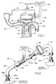
- Fig. 1 illustrates an exhaust gas recirculation system 10 for an internal combustion engine 12.
- the engine may be of conventional construction with a head 14 secured to a block 16 having pistons 18 slidably received in cylinders 20 and intake and exhaust valves 22 and 24 for each cylinder.
- Combustion air is supplied to the cylinder 20 from an intake manifold 26 and exhaust gases pass through an exhaust manifold 28.
- the engine fuel or gasoline is ignited by its plug 30.
- fuel is supplied to the engine through a fuel injector 32 or a carburetor mounted on the intake manifold.
- the engine may be of conventional construction, it will not be described in further detail.
- the EGR system comprises a control valve 34 with an exhaust gas inlet connected to the exhaust manifold by a coupler 36 embodying this invention.
- the outlet of the control valve is connected to the intake manifold either directly or through a tube 38.
- the control valve 34 is opened and closed in response to engine operating conditions by a control unit 40 which frequently is a part an electronic engine control module. Typically, while a cold engine is being started, the control unit closes the valve so that no exhaust gas is recirculated to the intake manifold. Once the engine starts, the control valve 34 opens to recirculate a portion of the hot exhaust gases through the intake manifold to more rapidly vaporize the fuel and heat the engine to its normal operating temperature.
- a transducer 42 is connected to taps on opposite sides of a venturi in the coupler to sense a differential pressure across the venturi and produce a preferably electric signal in response to variations in and indicative of the magnitude of this differential pressure.
- the output of the transducer is connected to the control unit through electric wires 43.
- the coupler has a body 44 connected by an inlet tube 48 to the exhaust manifold at one end.
- the other end of body 44 is connected by an outlet tube 50 to the inlet of the control valve 34.
- the outlet of the control valve is connected to a rigid tube 52 connected to the intake manifold.
- body 44 has a through passage 46 and a venturi 53 is formed in the body by a restricter plate or baffle 54 in the passage. Ports 56 and 58, one on each side of the restricter plate, communicate with separate pressure taps or tubes 60 and 62, each connected by hoses (not shown) to the transducer 42.
- the restricter plate 54 has a central orifice 64, as shown, with a rounded entry and preferably a chamfered entry 66 on the upstream side of the flow of exhaust gas through the passage in the direction of arrow A.
- the rounded or preferably chamfered entry 66 of the orifice is important to achieve consistent or substantially the same pressure drop for the same flow rate through the venturi from one venturi to another having the same configuration and the same nominal dimensions. Mass produced orifices having no rounded entry or chamfer 66 frequently have large variations in the pressure drop for the same flow rate, thus producing varying, erratic and unreliable signals for the control unit.
- the passage 46 has an inside diameter of .560 of an inch
- the restricter plate 54 has a thickness of about 0.140 of an inch
- the orifice has a diameter of about .275 of an inch
- the chamfer has an axial thickness of about 0.040 to 0.060 of an inch with its face inclined at an acute included angle to the axis of the orifice of 45°.
- the overall length of the coupler and the angular rotational orientation of its inlet and outlet tubes can be adjusted within predetermined limits of the coupler when connected between the exhaust manifold and the control valve.
- the intake tube has an enlarged diameter 48a adjacent one end telescopically receivable in a counterbore in a threaded sleeve 45 on one end of the body 44 which communicates with the passage 46.
- the intake tube is coupled and sealed to the body by a collar 49 encircling the enlarged tubular portion 48a and in assembly is threaded onto the sleeve 45.
- the collar 49 has a cam surface 68 which is inclined and circumferentially continuous which engages the outer periphery of the free end of the sleeve 45 and swages or permanently deforms it generally radially inwardly into sealing engagement with the enlarged portion of the tube 48 as the collar 49 is threaded onto the sleeve.
- the inside diameter of the counterbored sleeve 45 is somewhat larger than the outside diameter of the large end portion 48a of the inlet tube and the inside diameter of the bore of the collar 49 is somewhat larger than the outside diameter of the main portion of the inlet tube.
- the inside diameter bore through the collar is also somewhat smaller than the outside diameter of the end portion of the tube 48. Limited changes in the rotational orientation of the inlet tube to the body and hence the outlet tube are also permitted by this coupling construction arrangement.
- the other end of the inlet tube has a coupling collar 48b slidably received thereon which terminates in a flange 48c for connecting the tube to a connector fitting 48d connected to the exhaust manifold.
- the collar 48b, tube flange 48c and connector fitting 48d provide a sealed or gas tight connection and may be of conventional construction.
- One end of the outlet tube 50 is received in a counterbore in the other end of passage 46 and is sealed to the body, such as by brazing.
- a coupling collar 50a is received on the tube which has a flare 50b on its end for sealing engagement with a threaded fitting 50c connected to the inlet of the valve.
- the threaded collar 50a, tube flare 50b and coupling 50c may all be of conventional construction.
- the valve 34 has a curved outlet tube 52 with a conventional threaded coupling collar 52a and flare end 52b which cooperates with a complimentary fitting 52con the intake manifold to sealingly connect the outlet tube 50 to the intake manifold.
- the coupler is installed on an engine by first loosely assembling the inlet and outlet tubes 48, 50 to the exhaust and inlet manifolds, respectively.
- the collars 48b, 50a and 52a are then tightened sufficiently to seal and secure the inlet tube 48 to the exhaust manifold, the outlet tube 50 to the valve 34 and the valve outlet tube 52 to the intake manifold. This also aligns and positions the intake tube in the body of the coupler without stressing, bending or flexing any of the components by the assembly.
- the collar 49 is tightened sufficiently to swage and permanently deform the end portions of the nipple of the coupler into sealing engagement with the enlarged portion 48a of the inlet tube.
- this coupling assembly accommodates substantial variation in the manufacturing and assembly tolerances and the location of all of the couplers, components, the valve, the outlet tube of the valve, the intake manifold, exhaust manifold, and mounting of the intake and exhaust manifolds on the engine block relative to each other.
- EGR systems and couplers there are substantial variations in tolerances, and the precise location and orientation of components to each other all of which are accommodated by the coupler assembly of this invention and its method of assembly to an engine.
Landscapes
- Engineering & Computer Science (AREA)
- Chemical & Material Sciences (AREA)
- Combustion & Propulsion (AREA)
- Mechanical Engineering (AREA)
- General Engineering & Computer Science (AREA)
- Physics & Mathematics (AREA)
- Fluid Mechanics (AREA)
- Analytical Chemistry (AREA)
- Exhaust-Gas Circulating Devices (AREA)
Description
- This invention relates generally to an exhaust gas recirculation (EGR) system for an automotive-type engine for returning part of the exhaust gas of the engine to the intake manifold. More particularly, the invention relates to an adjustable exhaust recirculation pressure differential coupler to be mounted between an intake and an exhaust manifold of the engine.
- An EGR system, as is known, recirculates part of the exhaust gas back to the intake of an engine for reducing harmful nitrous oxide emissions. Fuel consumption and engine performance are affected by the recirculated exhaust gas flow. For example, engine performance may be affected by the temperature of the exhaust gas which is higher than that of the fresh air-fuel mixture introduced into the combustion chamber. The "hot" exhaust gas acts to heat up the combustible mixture thus facilitating the combustibility of the air-fuel mixture. As is known, the amount of exhaust gas returned is controlled by an EGR valve that is opened and closed by a control unit depending on operating conditions of the engine. To minimize exhaust gas emissions, it is important to accurately control the amount of exhaust gas recirculated according to engine operating conditions, such as, engine speed, temperature, altitude, exhaust gas pressure and temperature. Typically, with a cold start of the engine the EGR valve is initially closed to prevent recirculation, opened immediately after starting to recirculate exhaust gas to more quickly heat the engine and promote more complete combustion of fuel, and then closed when the engine warms up to operating temperature.
- FR-A-2,190,160 discloses a EGR system with a exhaust recirculation differential coupler comprising a valve and a elastomeric tube. Controlling the EGR system is achieved by the valve using the pressure difference of the exhaust gases vs. the atmospheric gases activating a disk having two species of openings to be switched between two positions. The above-mentioned EGR system does not provide for a continuous control of the recirculation system.
- Other prior couplers were one-piece steel tube as disclosed e.g. in US-P-4,148,286, some of them comprising an integral and slightly flexible bellows section. An orifice was disposed in the tube with only one pressure tap on one side of the orifice for a pressure sensor providing a signal used in controlling the EGR valve. The one-piece tube required close manufacturing and assembly tolerances for both the coupler and the engine to accurately locate the exhaust manifold and intake manifold mounting surface for the coupler. In service, the coupler became stressed, fatigued and cracked which resulted in expensive warranty, service and replacement costs for both manufacturers and consumers.
- The problem of the invention is to provide an EGR coupler which provides an improved differential pressure control signal, is easily adjustable to accommodate a wide variation in manufacturing and assembly tolerances, eliminates stress and cracking in use, has a long and improved useful life in service, is of relatively simple design and economical manufacture and assembly, and can be used on both new engines and utilized to retrofit and replace EGR couplers on engines already in the field. The problem is solved by an EGR coupler characterized in claim 1.
- The EGR coupler is adapted to be mounted between the exhaust manifold and an EGR control valve connected to an engine intake manifold. The EGR coupler has a baffle with a chamfered orifice forming a venturi therein for creating an exhaust gas pressure differential within the coupler. At least one but preferably two pressure taps, one on each side of the baffle, are provided for the exhaust gas pressure differential.
- The EGR coupler also has a telescoping assembly adjustable axially and rotatably to increase flexibility in installation and decrease stress cracking.
- These and other objects, features and advantages of this invention, appended claims and accompanying drawings in which:
- Fig. 1
- is a schematic diagram of an EGR system for an engine utilizing a coupler of this invention,
- Fig. 2
- is an exploded side view of the EGR coupler embodying this invention disposed between the exhaust manifold and a control valve connected to an intake manifold of an engine, and
- FIG. 3
- is a cross sectional view through lines 3-3 of FIG. 2.
- Fig. 1 illustrates an exhaust
gas recirculation system 10 for an internal combustion engine 12. The engine may be of conventional construction with ahead 14 secured to ablock 16 havingpistons 18 slidably received incylinders 20 and intake andexhaust valves cylinder 20 from anintake manifold 26 and exhaust gases pass through anexhaust manifold 28. The engine fuel or gasoline is ignited by itsplug 30. Typically, fuel is supplied to the engine through afuel injector 32 or a carburetor mounted on the intake manifold. As the engine may be of conventional construction, it will not be described in further detail. - The EGR system comprises a
control valve 34 with an exhaust gas inlet connected to the exhaust manifold by acoupler 36 embodying this invention. The outlet of the control valve is connected to the intake manifold either directly or through atube 38. Thecontrol valve 34 is opened and closed in response to engine operating conditions by acontrol unit 40 which frequently is a part an electronic engine control module. Typically, while a cold engine is being started, the control unit closes the valve so that no exhaust gas is recirculated to the intake manifold. Once the engine starts, thecontrol valve 34 opens to recirculate a portion of the hot exhaust gases through the intake manifold to more rapidly vaporize the fuel and heat the engine to its normal operating temperature. When the engine reaches a predetermined elevated temperature, the valve again closes to stop further recirculation of exhaust gas. To provide an indication of the volume or quantity of gas being recirculated with thevalve 34 open, in accordance with this invention, atransducer 42 is connected to taps on opposite sides of a venturi in the coupler to sense a differential pressure across the venturi and produce a preferably electric signal in response to variations in and indicative of the magnitude of this differential pressure. The output of the transducer is connected to the control unit throughelectric wires 43. - As shown in Fig. 2, the coupler has a
body 44 connected by aninlet tube 48 to the exhaust manifold at one end. The other end ofbody 44 is connected by anoutlet tube 50 to the inlet of thecontrol valve 34. The outlet of the control valve is connected to arigid tube 52 connected to the intake manifold. - As shown in Fig. 3,
body 44 has a throughpassage 46 and aventuri 53 is formed in the body by a restricter plate or baffle 54 in the passage.Ports tubes transducer 42. The restricter plate 54 has acentral orifice 64, as shown, with a rounded entry and preferably achamfered entry 66 on the upstream side of the flow of exhaust gas through the passage in the direction of arrow A. - In mass producing orifices, the rounded or preferably
chamfered entry 66 of the orifice is important to achieve consistent or substantially the same pressure drop for the same flow rate through the venturi from one venturi to another having the same configuration and the same nominal dimensions. Mass produced orifices having no rounded entry orchamfer 66 frequently have large variations in the pressure drop for the same flow rate, thus producing varying, erratic and unreliable signals for the control unit. - In one practical embodiment of the coupler for a V-6 engine, the
passage 46 has an inside diameter of .560 of an inch, the restricter plate 54 has a thickness of about 0.140 of an inch, the orifice has a diameter of about .275 of an inch and the chamfer has an axial thickness of about 0.040 to 0.060 of an inch with its face inclined at an acute included angle to the axis of the orifice of 45°. When gas flows through thepassage 46, theventuri 53 in the restricter plate 54 creates a pressure differential across thetubes - In accordance with another feature of the invention, the overall length of the coupler and the angular rotational orientation of its inlet and outlet tubes can be adjusted within predetermined limits of the coupler when connected between the exhaust manifold and the control valve.
- As shown in Figs. 2 and 3, the intake tube has an enlarged
diameter 48a adjacent one end telescopically receivable in a counterbore in a threadedsleeve 45 on one end of thebody 44 which communicates with thepassage 46. The intake tube is coupled and sealed to the body by acollar 49 encircling the enlargedtubular portion 48a and in assembly is threaded onto thesleeve 45. Thecollar 49 has acam surface 68 which is inclined and circumferentially continuous which engages the outer periphery of the free end of thesleeve 45 and swages or permanently deforms it generally radially inwardly into sealing engagement with the enlarged portion of thetube 48 as thecollar 49 is threaded onto the sleeve. - Preferably, to facilitate assembly by permitting the axis of the
tube 48 to be somewhat skewed or inclined to the axis of the passage of thebody 44 without unduly stressing or flexing either the tube or the body, the inside diameter of thecounterbored sleeve 45 is somewhat larger than the outside diameter of thelarge end portion 48a of the inlet tube and the inside diameter of the bore of thecollar 49 is somewhat larger than the outside diameter of the main portion of the inlet tube. To retain the collar on thetube 48, preferably the inside diameter bore through the collar is also somewhat smaller than the outside diameter of the end portion of thetube 48. Limited changes in the rotational orientation of the inlet tube to the body and hence the outlet tube are also permitted by this coupling construction arrangement. - Preferably, the other end of the inlet tube has a
coupling collar 48b slidably received thereon which terminates in aflange 48c for connecting the tube to a connector fitting 48d connected to the exhaust manifold. Thecollar 48b,tube flange 48c and connector fitting 48d provide a sealed or gas tight connection and may be of conventional construction. - One end of the
outlet tube 50 is received in a counterbore in the other end ofpassage 46 and is sealed to the body, such as by brazing. To connect the outlet tube to the intake valve, acoupling collar 50a is received on the tube which has aflare 50b on its end for sealing engagement with a threaded fitting 50c connected to the inlet of the valve. The threadedcollar 50a,tube flare 50b andcoupling 50c may all be of conventional construction. Thevalve 34 has acurved outlet tube 52 with a conventional threadedcoupling collar 52a and flareend 52b which cooperates with a complimentary fitting 52con the intake manifold to sealingly connect theoutlet tube 50 to the intake manifold. - Typically, the coupler is installed on an engine by first loosely assembling the inlet and
outlet tubes collars inlet tube 48 to the exhaust manifold, theoutlet tube 50 to thevalve 34 and thevalve outlet tube 52 to the intake manifold. This also aligns and positions the intake tube in the body of the coupler without stressing, bending or flexing any of the components by the assembly. Thereafter, thecollar 49 is tightened sufficiently to swage and permanently deform the end portions of the nipple of the coupler into sealing engagement with theenlarged portion 48a of the inlet tube. - Thus, this coupling assembly accommodates substantial variation in the manufacturing and assembly tolerances and the location of all of the couplers, components, the valve, the outlet tube of the valve, the intake manifold, exhaust manifold, and mounting of the intake and exhaust manifolds on the engine block relative to each other. In the mass production and assembly of internal combustion engines, EGR systems and couplers there are substantial variations in tolerances, and the precise location and orientation of components to each other all of which are accommodated by the coupler assembly of this invention and its method of assembly to an engine.
Claims (8)
- An exhaust recirculation pressure differential coupler (36), comprisinga coupler body (44) having a through passage (46) and ends and being arranged betweenan inlet tube (48) having a first end connected to one end of said coupler body (44) and adapted to be connected at a second end to an exhaust manifold (28), andan outlet tube (50) having a first end connected to the other end of said coupler body (44) and a second end adapted to be mounted to an inlet manifold (26) of an internal combustion engine (12) for receiving exhaust gases flowing from the exhaust manifold, anda venturi (53) in the coupler body (44),characterized in thatsaid coupler (36) further comprisesadjusting means to adjust the axial length of the coupler (36) and the angular orientation of said inlet tube (48) with respect to said coupler body (44).
- The exhaust recirculation pressure differential coupler as in claim 1
wherein said adjusting means comprises:a threaded sleeve (45) at said one end of said coupler body (44) having a counterbore;the first end of said inlet tube (48a) being enlarged and telescopically received in the counterbore; andsecuring means to lock said inlet tube to said coupler body. - The exhaust recirculation pressure differential coupler as in claim 2
wherein said securing means comprises:a collar (49) having a bore and threadably received on said sleeve (45), anda circumferentially continuous cam surface (68) for engaging and deforming an outer free end of said sleeve (45) radially inwardly into sealing engagement with the enlarged end of said inlet tube (48). - The exhaust recirculation pressure differential coupler as in claim 3
wherein said sleeve (45) has an inside diameter larger than an outer diameter of the first end of said inlet tube (48a). - The exhaust recirculation pressure differential coupler as in claim 3
wherein said collar (49) has an inside diameter smaller than an outer diameter of said sleeve (45). - The exhaust recirculation pressure differential coupler as in one of
claims 1 to 5 whereinsaid venturi (53) is formed in the body by a baffle plate (54) positioned wihtin said coupler body and having an orifice (64) for creating a pressure differential within the coupler body (44); andmeans on said coupler body (44) to accommodate pressure sensors on each side of said baffle plate (54). - The exhaust recirculation pressure differential coupler as in claim 6 whereinexhaust gases flow from said inlet tube (48) upstream of said baffle plate (54) through the orifice (64) and downstream through said outlet tube (50), andthe orifice (64) has a chamfer (66) on the upstream side of said baffle plate (54) to control exhaust gas flow therethrough.
- A method of assembling an exhaust recirculation pressure differential coupler (36) according to one of the claims 1 to 7 to an automative engine assembly,
the method comprising the steps of:a) connecting a first end of an outlet tube (50) to one end of said coupler body (44),b) connecting a first end of an inlet tube (48) to the other end of said coupler body (44),c) connecting a second end of the inlet tube (48) to an exhaust manifold,d) adjusting the inlet tube (48) relative to the coupler body (44) to align a second end of the outlet tube (50) to an intake manifold,e) connecting the second end of the outlet tube (50) to the intake manifold, andf) locking the inlet tube (48) to the coupler body (44).
Applications Claiming Priority (2)
| Application Number | Priority Date | Filing Date | Title |
|---|---|---|---|
| US863804 | 1992-04-06 | ||
| US07/863,804 US5188086A (en) | 1992-04-06 | 1992-04-06 | Exhaust gas recirculation coupler and differential venturi |
Publications (2)
| Publication Number | Publication Date |
|---|---|
| EP0564701A1 EP0564701A1 (en) | 1993-10-13 |
| EP0564701B1 true EP0564701B1 (en) | 1996-10-02 |
Family
ID=25341825
Family Applications (1)
| Application Number | Title | Priority Date | Filing Date |
|---|---|---|---|
| EP92118938A Expired - Lifetime EP0564701B1 (en) | 1992-04-06 | 1992-11-05 | Exhaust gas recirculation pressure diffenrential venturi and coupler |
Country Status (6)
| Country | Link |
|---|---|
| US (1) | US5188086A (en) |
| EP (1) | EP0564701B1 (en) |
| JP (1) | JPH05296110A (en) |
| BR (1) | BR9204604A (en) |
| CA (1) | CA2082110C (en) |
| DE (1) | DE69214273T2 (en) |
Families Citing this family (14)
| Publication number | Priority date | Publication date | Assignee | Title |
|---|---|---|---|---|
| US5203313A (en) * | 1992-06-19 | 1993-04-20 | Bundy Corporation | EGR venturi coupler |
| DE9315921U1 (en) * | 1993-10-19 | 1995-02-16 | Gustav Wahler Gmbh U. Co, 73730 Esslingen | Exhaust gas recirculation device |
| DE9416421U1 (en) * | 1994-10-12 | 1995-07-27 | Gustav Wahler Gmbh U. Co, 73730 Esslingen | Pipe connection of a device for exhaust gas recirculation |
| US5613479A (en) * | 1995-12-08 | 1997-03-25 | Ford Motor Company | Pressure feedback exhaust gas recirculation system |
| US5806308A (en) * | 1997-07-07 | 1998-09-15 | Southwest Research Institute | Exhaust gas recirculation system for simultaneously reducing NOx and particulate matter |
| US6230694B1 (en) | 1998-05-26 | 2001-05-15 | Siemens Canada, Ltd. | Calibration and testing of an automotive emission control module |
| US6116224A (en) * | 1998-05-26 | 2000-09-12 | Siemens Canada Ltd. | Automotive vehicle having a novel exhaust gas recirculation module |
| US6189520B1 (en) * | 1998-05-26 | 2001-02-20 | Siemens Canada Limited | Integration of sensor, actuator, and regulator valve in an emission control module |
| US6170476B1 (en) * | 1998-05-26 | 2001-01-09 | Siemens Canada Ltd. | Internal sensing passage in an exhaust gas recirculation module |
| US6138652A (en) * | 1998-05-26 | 2000-10-31 | Siemens Canada Limited | Method of making an automotive emission control module having fluid-power-operated actuator, fluid pressure regulator valve, and sensor |
| US6308694B1 (en) * | 1999-01-11 | 2001-10-30 | Ford Global Technologies, Inc. | Flow measurement and control |
| ITBO20030387A1 (en) * | 2003-06-23 | 2004-12-24 | Ferrari Spa | CONNECTION SYSTEM WITH FLUID SEAL BETWEEN TWO DUCTS PROVIDED |
| US8485311B2 (en) * | 2011-03-04 | 2013-07-16 | GM Global Technology Operations LLC | Air duct assembly for engine |
| DE102017212393A1 (en) * | 2017-07-19 | 2019-01-24 | Mahle International Gmbh | Area-wise flexible exhaust gas recirculation line |
Family Cites Families (17)
| Publication number | Priority date | Publication date | Assignee | Title |
|---|---|---|---|---|
| US1645347A (en) * | 1921-09-14 | 1927-10-11 | Packard Motor Car Co | Inlet manifold for internal-combustion motors |
| US1793556A (en) * | 1929-03-15 | 1931-02-24 | Maxmoor Corp | Apparatus for modifying and supplementing charges for internalcombustion engines |
| US2258902A (en) * | 1939-04-27 | 1941-10-14 | Marx Joseph | Exhaust gas return device for internal combustion engines |
| FR998800A (en) * | 1949-10-13 | 1952-01-23 | Hydrating device for internal combustion engines | |
| GB1417144A (en) * | 1972-06-20 | 1975-12-10 | Kinematics Ltd | Internal combustion engines |
| US4030740A (en) * | 1975-07-01 | 1977-06-21 | American Air Filter Company, Inc. | Expansion joint |
| US4148286A (en) * | 1976-10-01 | 1979-04-10 | Nippon Soken, Inc. | Exhaust gas recirculation system for an internal combustion engine |
| US4066052A (en) * | 1976-10-21 | 1978-01-03 | Moore Leota J | Exhaust recycling and carbon monoxide eliminator for combustion engines |
| US4201048A (en) * | 1977-10-13 | 1980-05-06 | Fisher Michael S | Exhaust system connector |
| US4196707A (en) * | 1978-07-31 | 1980-04-08 | General Motors Corporation | Exhaust gas recirculation control |
| US4485794A (en) * | 1982-10-04 | 1984-12-04 | United Technologies Diesel Systems, Inc. | Method and apparatus for controlling diesel engine exhaust gas recirculation partly as a function of exhaust particulate level |
| JPS61152955A (en) * | 1984-12-25 | 1986-07-11 | Fuji Heavy Ind Ltd | Exhaust gas reflux quantity controller |
| US4715348A (en) * | 1985-08-31 | 1987-12-29 | Nippondenso Co., Ltd. | Self-diagnosis system for exhaust gas recirculation system of internal combustion engine |
| JPS6285161A (en) * | 1985-10-09 | 1987-04-18 | Mitsubishi Electric Corp | Exhaust gas recycling control device for engine |
| US4693226A (en) * | 1986-06-02 | 1987-09-15 | Ford Motor Company | EGR control system |
| US4875455A (en) * | 1987-04-28 | 1989-10-24 | Mazda Motor Corporation | Automobile exhaust gas recirculating system |
| US4932686A (en) * | 1989-07-13 | 1990-06-12 | General Motors Corporation | Telescoping connector for a fluid coupling assembly |
-
1992
- 1992-04-06 US US07/863,804 patent/US5188086A/en not_active Expired - Fee Related
- 1992-11-04 CA CA002082110A patent/CA2082110C/en not_active Expired - Fee Related
- 1992-11-05 DE DE69214273T patent/DE69214273T2/en not_active Expired - Fee Related
- 1992-11-05 EP EP92118938A patent/EP0564701B1/en not_active Expired - Lifetime
- 1992-11-20 JP JP4312082A patent/JPH05296110A/en active Pending
- 1992-11-27 BR BR9204604A patent/BR9204604A/en not_active IP Right Cessation
Also Published As
| Publication number | Publication date |
|---|---|
| CA2082110C (en) | 1999-10-05 |
| US5188086A (en) | 1993-02-23 |
| DE69214273D1 (en) | 1996-11-07 |
| CA2082110A1 (en) | 1993-10-07 |
| BR9204604A (en) | 1993-10-13 |
| DE69214273T2 (en) | 1997-04-17 |
| JPH05296110A (en) | 1993-11-09 |
| EP0564701A1 (en) | 1993-10-13 |
Similar Documents
| Publication | Publication Date | Title |
|---|---|---|
| US5188086A (en) | Exhaust gas recirculation coupler and differential venturi | |
| US5832905A (en) | Method and apparatus for providing multipoint gaseous fuel injection to an internal combustion engine | |
| JP2703736B2 (en) | Fuel injection device for internal combustion engine | |
| US3412718A (en) | Precision fuel metering system | |
| US5056309A (en) | Internal combustion engine, particularly otto engine | |
| US5203313A (en) | EGR venturi coupler | |
| JPH10122061A (en) | Egr system for multicylinder engine | |
| US6014961A (en) | Internal combustion engine intake sensing system | |
| WO1988002067A1 (en) | Fuel injection system component | |
| US20020170518A1 (en) | V-type 2-cylinder engine | |
| US10519903B2 (en) | Air inlet system | |
| US10883443B2 (en) | Integrated cylinder head fluid injection apparatus | |
| JPH0343464B2 (en) | ||
| US6502564B1 (en) | Exhaust gas recirculation system module | |
| JPS5916097B2 (en) | fuel injector | |
| GB2087479A (en) | Ic engine mixture intake system | |
| US4050245A (en) | Concentric dual engine exhaust system | |
| US6883501B2 (en) | Throttle and fuel injector assembly | |
| US6460523B1 (en) | EGR system for an internal combustion engine | |
| AU741692B2 (en) | A fuel vaporisation system | |
| JP2558435Y2 (en) | EGR passage mounting structure for resin intake manifold | |
| JP2001107808A (en) | Gas engine fuel supply system | |
| JP2018013098A (en) | Automotive engine | |
| JPH0658226A (en) | Fuel injection device for internal combustion engine |
Legal Events
| Date | Code | Title | Description |
|---|---|---|---|
| PUAI | Public reference made under article 153(3) epc to a published international application that has entered the european phase |
Free format text: ORIGINAL CODE: 0009012 |
|
| AK | Designated contracting states |
Kind code of ref document: A1 Designated state(s): BE DE ES FR GB IT SE |
|
| 17P | Request for examination filed |
Effective date: 19931207 |
|
| 17Q | First examination report despatched |
Effective date: 19940121 |
|
| GRAG | Despatch of communication of intention to grant |
Free format text: ORIGINAL CODE: EPIDOS AGRA |
|
| GRAG | Despatch of communication of intention to grant |
Free format text: ORIGINAL CODE: EPIDOS AGRA |
|
| GRAG | Despatch of communication of intention to grant |
Free format text: ORIGINAL CODE: EPIDOS AGRA |
|
| GRAH | Despatch of communication of intention to grant a patent |
Free format text: ORIGINAL CODE: EPIDOS IGRA |
|
| GRAH | Despatch of communication of intention to grant a patent |
Free format text: ORIGINAL CODE: EPIDOS IGRA |
|
| GRAA | (expected) grant |
Free format text: ORIGINAL CODE: 0009210 |
|
| AK | Designated contracting states |
Kind code of ref document: B1 Designated state(s): BE DE ES FR GB IT SE |
|
| PG25 | Lapsed in a contracting state [announced via postgrant information from national office to epo] |
Ref country code: IT Free format text: LAPSE BECAUSE OF FAILURE TO SUBMIT A TRANSLATION OF THE DESCRIPTION OR TO PAY THE FEE WITHIN THE PRE;WARNING: LAPSES OF ITALIAN PATENTS WITH EFFECTIVE DATE BEFORE 2007 MAY HAVE OCCURRED AT ANY TIME BEFORE 2007. THE CORRECT EFFECTIVE DATE MAY BE DIFFERENT FROM THE ONE RECORDED.SCRIBED TIME-LIMIT Effective date: 19961002 Ref country code: BE Effective date: 19961002 |
|
| ET | Fr: translation filed | ||
| REF | Corresponds to: |
Ref document number: 69214273 Country of ref document: DE Date of ref document: 19961107 |
|
| PGFP | Annual fee paid to national office [announced via postgrant information from national office to epo] |
Ref country code: SE Payment date: 19961115 Year of fee payment: 5 |
|
| PGFP | Annual fee paid to national office [announced via postgrant information from national office to epo] |
Ref country code: BE Payment date: 19961126 Year of fee payment: 5 |
|
| PGFP | Annual fee paid to national office [announced via postgrant information from national office to epo] |
Ref country code: ES Payment date: 19961129 Year of fee payment: 5 |
|
| PG25 | Lapsed in a contracting state [announced via postgrant information from national office to epo] |
Ref country code: SE Effective date: 19970102 |
|
| PG25 | Lapsed in a contracting state [announced via postgrant information from national office to epo] |
Ref country code: ES Free format text: LAPSE BECAUSE OF FAILURE TO SUBMIT A TRANSLATION OF THE DESCRIPTION OR TO PAY THE FEE WITHIN THE PRESCRIBED TIME-LIMIT Effective date: 19970220 |
|
| PLBE | No opposition filed within time limit |
Free format text: ORIGINAL CODE: 0009261 |
|
| STAA | Information on the status of an ep patent application or granted ep patent |
Free format text: STATUS: NO OPPOSITION FILED WITHIN TIME LIMIT |
|
| 26N | No opposition filed | ||
| PGFP | Annual fee paid to national office [announced via postgrant information from national office to epo] |
Ref country code: FR Payment date: 19991019 Year of fee payment: 8 |
|
| PGFP | Annual fee paid to national office [announced via postgrant information from national office to epo] |
Ref country code: DE Payment date: 19991020 Year of fee payment: 8 Ref country code: GB Payment date: 19991020 Year of fee payment: 8 |
|
| PG25 | Lapsed in a contracting state [announced via postgrant information from national office to epo] |
Ref country code: GB Free format text: LAPSE BECAUSE OF NON-PAYMENT OF DUE FEES Effective date: 20001105 |
|
| GBPC | Gb: european patent ceased through non-payment of renewal fee |
Effective date: 20001105 |
|
| PG25 | Lapsed in a contracting state [announced via postgrant information from national office to epo] |
Ref country code: FR Free format text: LAPSE BECAUSE OF NON-PAYMENT OF DUE FEES Effective date: 20010731 |
|
| PG25 | Lapsed in a contracting state [announced via postgrant information from national office to epo] |
Ref country code: DE Free format text: LAPSE BECAUSE OF NON-PAYMENT OF DUE FEES Effective date: 20010801 |
|
| REG | Reference to a national code |
Ref country code: FR Ref legal event code: ST |