EP0564518B1 - Airbag - Google Patents
Airbag Download PDFInfo
- Publication number
- EP0564518B1 EP0564518B1 EP92901731A EP92901731A EP0564518B1 EP 0564518 B1 EP0564518 B1 EP 0564518B1 EP 92901731 A EP92901731 A EP 92901731A EP 92901731 A EP92901731 A EP 92901731A EP 0564518 B1 EP0564518 B1 EP 0564518B1
- Authority
- EP
- European Patent Office
- Prior art keywords
- straps
- bag
- fabrics
- woven
- airbag
- Prior art date
- Legal status (The legal status is an assumption and is not a legal conclusion. Google has not performed a legal analysis and makes no representation as to the accuracy of the status listed.)
- Expired - Lifetime
Links
- 239000004744 fabric Substances 0.000 claims abstract description 64
- 239000002759 woven fabric Substances 0.000 claims abstract description 18
- 239000000463 material Substances 0.000 claims description 21
- 238000009941 weaving Methods 0.000 claims description 7
- 238000004519 manufacturing process Methods 0.000 claims description 6
- 238000000034 method Methods 0.000 description 5
- 238000010438 heat treatment Methods 0.000 description 4
- 239000004952 Polyamide Substances 0.000 description 3
- 230000006378 damage Effects 0.000 description 3
- 229920002647 polyamide Polymers 0.000 description 3
- -1 polyethylene Polymers 0.000 description 3
- 239000004698 Polyethylene Substances 0.000 description 2
- 208000027418 Wounds and injury Diseases 0.000 description 2
- 229920003235 aromatic polyamide Polymers 0.000 description 2
- 239000000835 fiber Substances 0.000 description 2
- 208000014674 injury Diseases 0.000 description 2
- 229920000573 polyethylene Polymers 0.000 description 2
- OKTJSMMVPCPJKN-UHFFFAOYSA-N Carbon Chemical compound [C] OKTJSMMVPCPJKN-UHFFFAOYSA-N 0.000 description 1
- 229920000271 Kevlar® Polymers 0.000 description 1
- 239000004743 Polypropylene Substances 0.000 description 1
- 239000004760 aramid Substances 0.000 description 1
- 230000015572 biosynthetic process Effects 0.000 description 1
- 229910052799 carbon Inorganic materials 0.000 description 1
- 239000000919 ceramic Substances 0.000 description 1
- 239000011521 glass Substances 0.000 description 1
- 239000004761 kevlar Substances 0.000 description 1
- 229920001084 poly(chloroprene) Polymers 0.000 description 1
- 229920000728 polyester Polymers 0.000 description 1
- 229920000098 polyolefin Polymers 0.000 description 1
- 229920001155 polypropylene Polymers 0.000 description 1
Images


Classifications
-
- B—PERFORMING OPERATIONS; TRANSPORTING
- B60—VEHICLES IN GENERAL
- B60R—VEHICLES, VEHICLE FITTINGS, OR VEHICLE PARTS, NOT OTHERWISE PROVIDED FOR
- B60R21/00—Arrangements or fittings on vehicles for protecting or preventing injuries to occupants or pedestrians in case of accidents or other traffic risks
- B60R21/02—Occupant safety arrangements or fittings, e.g. crash pads
- B60R21/16—Inflatable occupant restraints or confinements designed to inflate upon impact or impending impact, e.g. air bags
- B60R21/23—Inflatable members
- B60R21/231—Inflatable members characterised by their shape, construction or spatial configuration
- B60R21/233—Inflatable members characterised by their shape, construction or spatial configuration comprising a plurality of individual compartments; comprising two or more bag-like members, one within the other
-
- B—PERFORMING OPERATIONS; TRANSPORTING
- B60—VEHICLES IN GENERAL
- B60R—VEHICLES, VEHICLE FITTINGS, OR VEHICLE PARTS, NOT OTHERWISE PROVIDED FOR
- B60R21/00—Arrangements or fittings on vehicles for protecting or preventing injuries to occupants or pedestrians in case of accidents or other traffic risks
- B60R21/02—Occupant safety arrangements or fittings, e.g. crash pads
- B60R21/16—Inflatable occupant restraints or confinements designed to inflate upon impact or impending impact, e.g. air bags
- B60R21/23—Inflatable members
- B60R21/231—Inflatable members characterised by their shape, construction or spatial configuration
- B60R21/2334—Expansion control features
- B60R21/2338—Tethers
-
- B—PERFORMING OPERATIONS; TRANSPORTING
- B60—VEHICLES IN GENERAL
- B60R—VEHICLES, VEHICLE FITTINGS, OR VEHICLE PARTS, NOT OTHERWISE PROVIDED FOR
- B60R21/00—Arrangements or fittings on vehicles for protecting or preventing injuries to occupants or pedestrians in case of accidents or other traffic risks
- B60R21/02—Occupant safety arrangements or fittings, e.g. crash pads
- B60R21/16—Inflatable occupant restraints or confinements designed to inflate upon impact or impending impact, e.g. air bags
- B60R21/23—Inflatable members
- B60R21/235—Inflatable members characterised by their material
-
- B—PERFORMING OPERATIONS; TRANSPORTING
- B60—VEHICLES IN GENERAL
- B60R—VEHICLES, VEHICLE FITTINGS, OR VEHICLE PARTS, NOT OTHERWISE PROVIDED FOR
- B60R21/00—Arrangements or fittings on vehicles for protecting or preventing injuries to occupants or pedestrians in case of accidents or other traffic risks
- B60R21/02—Occupant safety arrangements or fittings, e.g. crash pads
- B60R21/16—Inflatable occupant restraints or confinements designed to inflate upon impact or impending impact, e.g. air bags
- B60R21/23—Inflatable members
- B60R21/231—Inflatable members characterised by their shape, construction or spatial configuration
- B60R21/2334—Expansion control features
- B60R21/2338—Tethers
- B60R2021/23382—Internal tether means
-
- B—PERFORMING OPERATIONS; TRANSPORTING
- B60—VEHICLES IN GENERAL
- B60R—VEHICLES, VEHICLE FITTINGS, OR VEHICLE PARTS, NOT OTHERWISE PROVIDED FOR
- B60R21/00—Arrangements or fittings on vehicles for protecting or preventing injuries to occupants or pedestrians in case of accidents or other traffic risks
- B60R21/02—Occupant safety arrangements or fittings, e.g. crash pads
- B60R21/16—Inflatable occupant restraints or confinements designed to inflate upon impact or impending impact, e.g. air bags
- B60R21/23—Inflatable members
- B60R21/235—Inflatable members characterised by their material
- B60R2021/23533—Inflatable members characterised by their material characterised by the manufacturing process
- B60R2021/23542—Weaving
- B60R2021/23547—Weaving one piece weaving
Definitions
- the present invention relates to an airbag and to a method of making an airbag.
- Such an airbag might be inflated and used, for example, for the protection of occupants of a vehicle in the event of a collision.
- Inflatable airbags are being used increasingly in vehicles as safety restraints for use in the event of a collision. Such bags might be stowed in front of a passenger, and arranged to inflate rapidly in the event of a collision, so as to restrain the passenger and to prevent him or her from being thrown against hard surfaces within the vehicle and therefore from being injured.
- airbags have commonly been made from polyamide fabric, which might be coated with a layer of a gas impermeable material such as a chlorobutadiene rubber.
- a disadvantage of airbags forms from such materials is that they are relatively expensive to produce. Furthermore, they tend generally to be relatively bulky, which can make it difficult to store them in front of a passenger in a vehicle.
- Airbags disclosed in W0-A-90/09295 are provided with internal straps which extend between the upper and lower fabrics.
- the straps can control the configuration of the bag when it is inflated.
- the straps may be provided in a material which is stronger and resistant to shrinkage on exposure to heat. Such fibres may be woven into the upper and lower fabrics at the initial weaving stage.
- a heat treatment step can be used to force the upper and lower fabrics to shrink, so that the straps formed from shrink resistant material become loose.
- the configuration of the airbag when inflated can be adjusted by changing the points of contact between the straps and the upper and lower fabrics, by appropriate adjustment of the weave programme.
- the present invention provides an airbag which includes internal straps for control of the configuration of the bag when inflated which are interconnected.
- the straps confer significant advantages on the airbag and on techniques by which it might be manufactured.
- the invention provides an airbag, comprising upper and lower woven fabrics which are woven together in selected regions so as to define and to enclose at least partially between them a space, at least two straps being provided within the bag to control its configuration when inflated, the straps being connected to one another at a point between their ends, the ends of a first one of the straps being connected to one of the fabrics, and the ends of a second one of the straps being connected to the other of the fabrics.
- the airbag of the invention has significant advantages compared with airbags in which straps passed directly between two woven fabrics, and are not interconnected.
- the present invention allows the configuration of an inflated airbag to be controlled more precisely and conveniently than with previously known airbags.
- the configuration can be adjusted by appropriate selection of variables such as:
- the straps may be connected to one another directly without use of another component, as a result of one of the straps passing through the other of the straps.
- it can be preferred to connect the straps together by means of a connector element.
- the straps be connected to one another by means of a connector element.
- a connector element This has the particular advantage that it allows an airbag to be formed by weaving with straps extending between its upper and lower fabrics, and with the seam at which the upper and lower fabrics are joined located within the bag. This result can be achieved by weaving the upper and lower fabrics together so as to define a space, with the straps provided on the outer exposed surfaces of the fabrics. The resulting bag can then be turned inside out, so that the seam and the straps are provided on what becomes the internal surfaces of the bag.
- a further advantage of this embodiment is that, with the seam at which the upper and lower fabrics are joined being inside the airbag, the risk of injury in the event of impact between the bag and a person, for example in a collision involving a vehicle in which that person is a passenger, arising from abrasive contact with a hard edge of such a seam, is significantly reduced.
- the present invention allows this advantage to be realised, in an airbag in which straps are provided extending between the upper and lower fabrics
- the connector element by which the first and second straps are connected to one another may be rigid or flexible. It may be relatively small so that the straps are held against one another, in which case it could be, for example, a clip or a flexible tie. Otherwise, it may be relatively long so that the first and second straps are connected to one another, but remain a certain distance apart.
- a connector element might be provided by, for example, a connector strap, which may be formed of the same material as the first and second straps so that it is flexible.
- the use of a relatively long connector element has the advantage that the configuration of the resulting inflated bag can be controlled yet further by adjustment of the length of the connector element. In this arrangement, the straps can be relatively short, so that they provide little more than just anchorage points for the ends of the connector element.
- the materials of the straps and from which the woven fabrics are formed may be the same. However, it is preferred that the materials are different.
- the material of the straps may be resistant to shrinkage when exposed to heat, while the material from which the fabrics are woven may be unstable so that they shrink to a small extent when exposed to heat. This allows straps to be incorporated into the fabrics as the fabrics are woven, and subsequently to be made slack by an appropriate heat treatment of the fabric so that the straps can allow the bag to expand on inflation.
- the materials from which the fabrics are woven will generally be polymeric, such as a polyamide or a polyester, or a polyolefins (for example polyethylene and polypropylene).
- polymeric such as a polyamide or a polyester, or a polyolefins (for example polyethylene and polypropylene).
- polyolefins for example polyethylene and polypropylene.
- other materials for the fibres from which the fabrics are woven include aramids, carbon, glass and ceramic, as well as appropriately treated natural fibres.
- the materials for the straps may also be selected from the lists set out above.
- a factor which can, in some situations, affect the choice of material for the straps is that they should be capable of withstanding the heat which is generated when the airbag is inflated.
- inflation can take place rapidly, by means of a gas which is supplied to the bag explosively.
- Considerable heat can be generated on inflation, and it is important that the straps by which the configuration of the inflated bag is controlled be able to withstand that heat, in order to prevent failure when the bag is inflated.
- Fusible fibres may be provided in at least an edge region of the airbag in which fibres from which the fabrics are formed to run approximately tangential to that edge. Such fusible fibres can reduce fraying of the fibres of the fabrics once exposed to heat to cause them to fuse. Airbags which include such fusile fibres are disclosed in the application which is being filed on the same day as this application and which bears the reference GB-A-2 251 410.
- the invention includes methods of making airbags.
- a preferred method comprises:
- the airbag of the present invention may be square. Preferably, it has a non-square shape, especially a generally rounded shape such as a circular shape.
- a generally rounded shape such as a circular shape.
- the formation of an airbag which has a generally rounded shape has the advantage that it is somewhat less bulky than might otherwise be the case.
- each strap may comprise a single fibre or, for some applications, a plurality of fibres, which may be woven or interlaced in some other way.
- the use of a plurality of fibres has the advantage that the straps are better able to withstand loads which are applied when the bag is inflated.
- Each of the straps may be formed as one or more lengths.
- each strap may be formed in two sections which may be connected to one another after the sections have been connected to their respective fabric.
- an airbag may be provided with two straps which are connected to one another at their midpoints, each of the straps being formed on two sections of approximately equal length which are themselves joined together.
- the orientation of the straps on their respective fabrics will depend on, amongst other things, the way in which they are connected to one another.
- the two straps When the straps are connected to one another by one of the straps passing through the other, the two straps will generally be arranged approximately perpendicular to one another. In this case, it will generally be convenient for one of the straps to be provided in the weft direction of its respective fabric, while the other of the straps is provided in the warp direction of its fabric. However, even when connected by one of the straps passing through the other, the two straps may be arranged approximately parallel to one another if desired. When the straps are connected to one another by means of a connector element, the straps will generally be arranged approximately parallel to one another, so that, for example, both extend in the warp direction of their respective fabrics, or both extend in the weft direction of their respective fabrics.
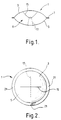
- figures 1 and 2 show an airbag 1 comprising an upper woven fabric 3 and a lower woven fabric 5.
- the upper and lower fabrics are woven together in an edge region 7 so as to define and to enclose between them a space 9.
- a first strap 15 is connected at each of its ends to the upper fabric 3.
- the strap extends in the warp direction of the fabric, and is woven into the fabric.
- a second strap 17 is connected at each of its ends to the lower fabric 5, the second strap also being connected by being woven into the fabric, and extending in the weft direction of the fabric.
- the first strap 15 is connected to the second strap 17 as a result of the first strap passing through the second strap.
- the first and second straps 15, 17 control the configuration of the bag.
- the material of the fibres from which the upper and lower woven fabrics 3, 5 are formed is a polyamide.
- the material of the first and second straps 15, 17 is an aramid, such as that sold under the trade mark KEVLAR.
- Polyethylene fibres are incorporated in the four edge regions 21 in which the fibres of the upper and lower fabrics (either weft or warp) run approximately tangential to that edge.
- Figure 3 shows an airbag at successive stages in its manufacture.
- Figure 3a shows upper and lower woven fabrics 31, 33, which are woven together in an edge region 35 so as to define and to enclose between them a space 37.
- a first strap 39 is provided on the outer surface of the upper woven fabric 31, and a second strap 41 is provided on the outer surface of the lower woven fabric 33.
- the materials of the straps, and of the woven fabrics 31, 33, are selected so that exposure of the bag to an elevated temperature causes its configuration to change from that shown in figure 3a (in which the straps 39, 41 are relatively tight) to that shown in figure 3b (in which the straps 39, 41 are relatively loose relative to the fabrics).
- This can be achieved by use of a heat unstable fibre to form the upper and lower woven fabrics 31, 33, and by using a heat stable material for the straps 39,41.
- the bag Before or after the heat treatment step, the bag is turned inside out. Access to the inside of the bag during this step can be reached through an aperture through which, when the bag is in use, a gas is supplied to cause it to inflate.
- a gas is supplied to cause it to inflate.
- Figure 3c shows the bag after is has been turned inside out.
- a connector element 45 in the form of a flexible strap is provided to connect the first strap 39 to the second strap 41. Access to the first and second straps 39, 41 to connect them by means of the connector element 45 can be gained through the opening through which gas for inflation is supplied.
- the edge region 35 at which the upper and lower fabrics 31, 33 are joined is located inside the bag, so that the risk of injury to a person on impact with the bag, arising from a hard edge region, is significantly reduced.
- the configuration of the air bag shown in figure 3, once it has been inflated, can be controlled by appropriate adjustment of a number of variables. These include the number of first and second straps provided on each of the upper and lower woven fabrics 31, 33, the positions at which the first and second straps 39, 41 are connected to the fabrics 31, 33 (by adjusting the distance a and b), and the length of the connector element 45.
- a flexible connector element such as that shown in figure 3c is preferred since it occupies a small amount of space within the bag when it is collapsed, and is unlikely to damage either the bag (when collapsed), or a person in the event of impact.
- the embodiment of the air bag shown in figure 4 differs from that shown in figure 3 in that is includes two pairs of straps, 51,53, and 57, 59, a strap of each pair being provided on the upper and lower fabrics 61, 63 respectively.
- the straps of each pair are relatively short, and are interconnected by means of flexible connector elements 65,67.
Landscapes
- Engineering & Computer Science (AREA)
- Mechanical Engineering (AREA)
- Air Bags (AREA)
- Woven Fabrics (AREA)
Abstract
Description
- The present invention relates to an airbag and to a method of making an airbag. Such an airbag might be inflated and used, for example, for the protection of occupants of a vehicle in the event of a collision.
- Inflatable airbags are being used increasingly in vehicles as safety restraints for use in the event of a collision. Such bags might be stowed in front of a passenger, and arranged to inflate rapidly in the event of a collision, so as to restrain the passenger and to prevent him or her from being thrown against hard surfaces within the vehicle and therefore from being injured. Such airbags have commonly been made from polyamide fabric, which might be coated with a layer of a gas impermeable material such as a chlorobutadiene rubber. However, a disadvantage of airbags forms from such materials is that they are relatively expensive to produce. Furthermore, they tend generally to be relatively bulky, which can make it difficult to store them in front of a passenger in a vehicle.
- More recently, it has been proposed to form airbags by weaving upper and lower fabrics simultaneously, the fabrics being woven together in selected regions so as to define and to enclose at least partially between them a space. It has been found that circular airbags can be formed in this way, and the resulting airbags have been found to be significantly less bulky than earlier airbags formed from coated fabrics, and to be capable of manufacture relatively cheaply. Such airbags are disclosed in our W0-A-90/09295. The subject matter disclosed in that document is incorporated in this specification by this reference to the document.
- Airbags disclosed in W0-A-90/09295 are provided with internal straps which extend between the upper and lower fabrics. The straps can control the configuration of the bag when it is inflated. The straps may be provided in a material which is stronger and resistant to shrinkage on exposure to heat. Such fibres may be woven into the upper and lower fabrics at the initial weaving stage. By appropriate selection of a material for the upper and lower fabrics, a heat treatment step can be used to force the upper and lower fabrics to shrink, so that the straps formed from shrink resistant material become loose.
- The configuration of the airbag when inflated can be adjusted by changing the points of contact between the straps and the upper and lower fabrics, by appropriate adjustment of the weave programme.
- The present invention provides an airbag which includes internal straps for control of the configuration of the bag when inflated which are interconnected. The straps confer significant advantages on the airbag and on techniques by which it might be manufactured.
- Accordingly, in one aspect, the invention provides an airbag, comprising upper and lower woven fabrics which are woven together in selected regions so as to define and to enclose at least partially between them a space, at least two straps being provided within the bag to control its configuration when inflated, the straps being connected to one another at a point between their ends, the ends of a first one of the straps being connected to one of the fabrics, and the ends of a second one of the straps being connected to the other of the fabrics.
- It has been found that the airbag of the invention has significant advantages compared with airbags in which straps passed directly between two woven fabrics, and are not interconnected. In particular, the present invention allows the configuration of an inflated airbag to be controlled more precisely and conveniently than with previously known airbags. For example, the configuration can be adjusted by appropriate selection of variables such as:
- (a) the anchorage points of the straps on the fabrics; and
- (b) the lengths of the straps.
- (c) shrinkage potential of the yarns: none, high or low
- The straps may be connected to one another directly without use of another component, as a result of one of the straps passing through the other of the straps. However, for many applications, it can be preferred to connect the straps together by means of a connector element.
- It is particularly preferred that the straps be connected to one another by means of a connector element. This has the particular advantage that it allows an airbag to be formed by weaving with straps extending between its upper and lower fabrics, and with the seam at which the upper and lower fabrics are joined located within the bag. This result can be achieved by weaving the upper and lower fabrics together so as to define a space, with the straps provided on the outer exposed surfaces of the fabrics. The resulting bag can then be turned inside out, so that the seam and the straps are provided on what becomes the internal surfaces of the bag.
- The possibility of providing an airbag with its seam within it has the significant advantage that the tendency of the fabrics to fray at their edges around the seam is significantly reduced, so that the tendency of the seam to open is also reduced. A further advantage of this embodiment is that, with the seam at which the upper and lower fabrics are joined being inside the airbag, the risk of injury in the event of impact between the bag and a person, for example in a collision involving a vehicle in which that person is a passenger, arising from abrasive contact with a hard edge of such a seam, is significantly reduced. The present invention allows this advantage to be realised, in an airbag in which straps are provided extending between the upper and lower fabrics
- The connector element by which the first and second straps are connected to one another may be rigid or flexible. It may be relatively small so that the straps are held against one another, in which case it could be, for example, a clip or a flexible tie. Otherwise, it may be relatively long so that the first and second straps are connected to one another, but remain a certain distance apart. Such a connector element might be provided by, for example, a connector strap, which may be formed of the same material as the first and second straps so that it is flexible. The use of a relatively long connector element has the advantage that the configuration of the resulting inflated bag can be controlled yet further by adjustment of the length of the connector element. In this arrangement, the straps can be relatively short, so that they provide little more than just anchorage points for the ends of the connector element.
- The materials of the straps and from which the woven fabrics are formed may be the same. However, it is preferred that the materials are different. For example, the material of the straps may be resistant to shrinkage when exposed to heat, while the material from which the fabrics are woven may be unstable so that they shrink to a small extent when exposed to heat. This allows straps to be incorporated into the fabrics as the fabrics are woven, and subsequently to be made slack by an appropriate heat treatment of the fabric so that the straps can allow the bag to expand on inflation.
- The materials from which the fabrics are woven will generally be polymeric, such as a polyamide or a polyester, or a polyolefins (for example polyethylene and polypropylene). Examples of other materials for the fibres from which the fabrics are woven include aramids, carbon, glass and ceramic, as well as appropriately treated natural fibres.
- The materials for the straps may also be selected from the lists set out above.
- A factor which can, in some situations, affect the choice of material for the straps is that they should be capable of withstanding the heat which is generated when the airbag is inflated. When the airbag is used for the protection of occupants of a vehicle in the event of a collision, inflation can take place rapidly, by means of a gas which is supplied to the bag explosively. Considerable heat can be generated on inflation, and it is important that the straps by which the configuration of the inflated bag is controlled be able to withstand that heat, in order to prevent failure when the bag is inflated.
- Fusible fibres may be provided in at least an edge region of the airbag in which fibres from which the fabrics are formed to run approximately tangential to that edge. Such fusible fibres can reduce fraying of the fibres of the fabrics once exposed to heat to cause them to fuse. Airbags which include such fusile fibres are disclosed in the application which is being filed on the same day as this application and which bears the reference GB-A-2 251 410.
- The invention includes methods of making airbags. A preferred method comprises:
- (a) weaving upper and lower fabrics simultaneously, the fabrics being woven together in selected regions so as to define and to enclose at least partially between them a space, each of the fabrics having woven in it a strap which is loose relative to the fabric, and which is provided on the outer surface of its respective fabric;
- (b) turning the bag formed from the woven fabrics inside-out, so that the straps are on the inside of the bag; and
- (c) connecting the straps to one another.
- Appropriate techniques for weaving the upper and lower fabrics of the airbag are disclosed in WO-A-90/09295. Among those techniques is one in which a succession of airbags are formed adjacent to one another from upper and lower fabrics, a selvage being provided along the edges of the fabrics extending in the warp direction.
- The airbag of the present invention may be square. Preferably, it has a non-square shape, especially a generally rounded shape such as a circular shape. The formation of an airbag which has a generally rounded shape has the advantage that it is somewhat less bulky than might otherwise be the case.
- When the airbag is provided with straps in the form of fibres, such as fibres which are woven into the upper and lower fabrics of the bag, each strap may comprise a single fibre or, for some applications, a plurality of fibres, which may be woven or interlaced in some other way. The use of a plurality of fibres has the advantage that the straps are better able to withstand loads which are applied when the bag is inflated. Each of the straps may be formed as one or more lengths. For example, each strap may be formed in two sections which may be connected to one another after the sections have been connected to their respective fabric. In one embodiment, for example, an airbag may be provided with two straps which are connected to one another at their midpoints, each of the straps being formed on two sections of approximately equal length which are themselves joined together.
- The orientation of the straps on their respective fabrics will depend on, amongst other things, the way in which they are connected to one another. When the straps are connected to one another by one of the straps passing through the other, the two straps will generally be arranged approximately perpendicular to one another. In this case, it will generally be convenient for one of the straps to be provided in the weft direction of its respective fabric, while the other of the straps is provided in the warp direction of its fabric. However, even when connected by one of the straps passing through the other, the two straps may be arranged approximately parallel to one another if desired. When the straps are connected to one another by means of a connector element, the straps will generally be arranged approximately parallel to one another, so that, for example, both extend in the warp direction of their respective fabrics, or both extend in the weft direction of their respective fabrics.
- Embodiments of the present invention will now be described by way of example with reference to the accompanying drawings, in which:
- Figure 1 is a sectional elevation through an airbag;
- Figure 2 is a plan view of the airbag shown in figure 1;
- Figure 3 consists of three sectional elevations through an airbag, in successive stages of manufacture; and
- Figure 4 consists of two sectional elevations through an airbag, in successive stages of manufacture.
- Referring to the drawings, figures 1 and 2 show an airbag 1 comprising an upper
woven fabric 3 and a lowerwoven fabric 5. The upper and lower fabrics are woven together in anedge region 7 so as to define and to enclose between them aspace 9. Afirst strap 15 is connected at each of its ends to theupper fabric 3. The strap extends in the warp direction of the fabric, and is woven into the fabric. Asecond strap 17 is connected at each of its ends to thelower fabric 5, the second strap also being connected by being woven into the fabric, and extending in the weft direction of the fabric. - The
first strap 15 is connected to thesecond strap 17 as a result of the first strap passing through the second strap. When the bag is inflated (as a result of supply of gas through an opening - not shown), the first andsecond straps - The material of the fibres from which the upper and lower
woven fabrics second straps edge regions 21 in which the fibres of the upper and lower fabrics (either weft or warp) run approximately tangential to that edge. - Figure 3 shows an airbag at successive stages in its manufacture. Figure 3a shows upper and lower woven
fabrics edge region 35 so as to define and to enclose between them aspace 37. Afirst strap 39 is provided on the outer surface of the upper wovenfabric 31, and asecond strap 41 is provided on the outer surface of the lower wovenfabric 33. The materials of the straps, and of the wovenfabrics straps straps fabrics straps - Before or after the heat treatment step, the bag is turned inside out. Access to the inside of the bag during this step can be reached through an aperture through which, when the bag is in use, a gas is supplied to cause it to inflate. When the bag is woven in such a way that that opening also shrinks when the bag is exposed to heat, it will be preferred to turn the bag inside out before the heat treatment step.
- Figure 3c shows the bag after is has been turned inside out. A
connector element 45 in the form of a flexible strap is provided to connect thefirst strap 39 to thesecond strap 41. Access to the first andsecond straps connector element 45 can be gained through the opening through which gas for inflation is supplied. - It will be seen that, as a result of turning the bag inside out, the
edge region 35 at which the upper andlower fabrics - The configuration of the air bag shown in figure 3, once it has been inflated, can be controlled by appropriate adjustment of a number of variables. These include the number of first and second straps provided on each of the upper and lower woven
fabrics second straps fabrics 31, 33 (by adjusting the distance a and b), and the length of theconnector element 45. - A flexible connector element such as that shown in figure 3c is preferred since it occupies a small amount of space within the bag when it is collapsed, and is unlikely to damage either the bag (when collapsed), or a person in the event of impact.
- The embodiment of the air bag shown in figure 4 differs from that shown in figure 3 in that is includes two pairs of straps, 51,53, and 57, 59, a strap of each pair being provided on the upper and
lower fabrics flexible connector elements
Claims (10)
- An airbag (1) comprising upper (3; 31; 61) and lower (5; 33; 63) woven fabrics which are woven together in selected regions so as to define and enclose at least partially between them a space (37, 9), at least two straps (15, 17; 39, 41; 51, 53; 57, 59) being provided within the bag to control its configuration when inflated, characterized therein, that the straps (15, 17; 39, 41; 51, 53; 57, 59) being connected to one another at a point between their ends, the ends of a first one of the straps (15; 39; 51; 57) being connected one of the fabrics (3; 31; 61) and the ends of a second one of the straps (17; 41; 53; 59) being connected to the other of the fabrics (5; 33; 63).
- A bag as claimed in claim 1 in which the straps are connected to one another as a result of one of the straps (15, 17) passing through the other of the straps (17, 15).
- A bag as claimed in claim 1 in which the straps are connected together by means of a connector element (45; 65; 67).
- A bag as claimed in claim 3 in which the connector element (45; 65; 67) is rigid or flexible.
- A bag as claimed in either of claims 3 or 4 in which the connector element (45; 65; 67) is relatively small so that the straps (15, 17; 39, 41; 51, 53, 57, 59) are held against one another.
- A bag as claimed in either of claims 3 or 4 in which the connector element (45; 65; 67) is relatively long so that the first (15; 39; 51; 57) and second (17; 41; 53; 59) straps are connected together but remain a certain distance apart.
- A bag as claimed in claim 6 in which the connector element is a connector strap of the same material as the first and second straps.
- A bag as claimed in any of claims 1 to 7 in which the straps (15 ... 59) are formed from the same material as the woven fabric (3 .... 63).
- A bag as claimed in any of claims 1 to 7 in which the straps are formed from a different material from the woven fabric.
- A method of making an airbag comprises:a) weaving upper (3; 31; 61) and lower (5; 33; 63) fabrics simultaneously, the fabrics being woven together in selective regions so as to define and enclose at least partially between them a space, each of the fabrics having woven in it a strap (15 ... 59) which is loose relative to the fabric, and which is provided on the outer surface of its respective fabric;b) turning the bag formed from the woven fabrics inside out so that the straps are on the inside of the bag; andc) connecting the straps (15; 17 .... 57; 59) to one another.
Applications Claiming Priority (3)
| Application Number | Priority Date | Filing Date | Title |
|---|---|---|---|
| GB909028173A GB9028173D0 (en) | 1990-12-28 | 1990-12-28 | Air bag |
| GB9028173 | 1990-12-28 | ||
| PCT/GB1991/002322 WO1992012028A1 (en) | 1990-12-28 | 1991-12-24 | Airbag |
Publications (2)
| Publication Number | Publication Date |
|---|---|
| EP0564518A1 EP0564518A1 (en) | 1993-10-13 |
| EP0564518B1 true EP0564518B1 (en) | 1995-11-15 |
Family
ID=10687665
Family Applications (1)
| Application Number | Title | Priority Date | Filing Date |
|---|---|---|---|
| EP92901731A Expired - Lifetime EP0564518B1 (en) | 1990-12-28 | 1991-12-24 | Airbag |
Country Status (5)
| Country | Link |
|---|---|
| EP (1) | EP0564518B1 (en) |
| AU (1) | AU9132891A (en) |
| DE (1) | DE69114727T2 (en) |
| GB (1) | GB9028173D0 (en) |
| WO (1) | WO1992012028A1 (en) |
Families Citing this family (3)
| Publication number | Priority date | Publication date | Assignee | Title |
|---|---|---|---|---|
| JPH04228648A (en) * | 1990-12-27 | 1992-08-18 | Bridgestone Corp | Air bag |
| DE4324487B4 (en) * | 1993-07-21 | 2006-03-30 | Bst Safety Textiles Gmbh | Textile hollow body and process for its production |
| CZ37795A3 (en) * | 1992-08-14 | 1995-11-15 | Johann Berger | Textile hollow body and process for producing thereof |
Family Cites Families (3)
| Publication number | Priority date | Publication date | Assignee | Title |
|---|---|---|---|---|
| US3879056A (en) * | 1972-02-21 | 1975-04-22 | Toyoda Boshoku Kk | Safety gas bag structure |
| US4988119A (en) * | 1988-10-14 | 1991-01-29 | Irvin Automotive Products, Inc. | Vehicle occupant restraint system |
| EP0458838B1 (en) * | 1989-02-16 | 1996-05-08 | Airbags International Limited | Air bag |
-
1990
- 1990-12-28 GB GB909028173A patent/GB9028173D0/en active Pending
-
1991
- 1991-12-24 WO PCT/GB1991/002322 patent/WO1992012028A1/en not_active Ceased
- 1991-12-24 EP EP92901731A patent/EP0564518B1/en not_active Expired - Lifetime
- 1991-12-24 DE DE69114727T patent/DE69114727T2/en not_active Expired - Fee Related
- 1991-12-24 AU AU91328/91A patent/AU9132891A/en not_active Abandoned
Also Published As
| Publication number | Publication date |
|---|---|
| WO1992012028A1 (en) | 1992-07-23 |
| AU9132891A (en) | 1992-08-17 |
| DE69114727D1 (en) | 1995-12-21 |
| EP0564518A1 (en) | 1993-10-13 |
| DE69114727T2 (en) | 1996-07-25 |
| GB9028173D0 (en) | 1991-02-13 |
Similar Documents
| Publication | Publication Date | Title |
|---|---|---|
| AU637785B2 (en) | Air bag | |
| US5651395A (en) | Circular air bag made of two simultaneously woven fabrics | |
| CA2181917C (en) | Air bag | |
| EP0611683B1 (en) | Air bag with reinforcing belts | |
| US5879767A (en) | Air bag | |
| JP4256093B2 (en) | Inflatable fabric | |
| US5046759A (en) | Braided fabric structure for seamless fabric confinements | |
| US6299205B1 (en) | Vehicle restraint system comprising an airbag having a looped pocket for inflation canister disposition | |
| CA2084320A1 (en) | Uncoated woven fabric and method of manufacturing same | |
| US20020020998A1 (en) | Multiple panel airbag and method | |
| JPH03176250A (en) | Air bag foundation | |
| EP0687596B1 (en) | Air bag | |
| JPH04189643A (en) | Bag body for vehicle air bag device | |
| WO1992012028A1 (en) | Airbag | |
| GB2251410A (en) | Vehicle air bags | |
| GB2282575A (en) | Air bags | |
| EP0585271B1 (en) | Gas-permeable fabric | |
| KR100546462B1 (en) | Fabric for airbags. | |
| CA1337207C (en) | Impact absorbing bag and manufacturing method thereof | |
| EP1097063A1 (en) | Vehicle restraint system comprising an airbag having an integrated mouth | |
| KR20190080047A (en) | OPW Side Curtain Airbag | |
| CA1337944C (en) | Impact absorbing bag and manufacturing method thereof | |
| JP2003171841A (en) | Airbag base fabric and airbag | |
| KR20100136699A (en) | Tubular fabric member for airbag gas injection and manufacturing method thereof | |
| JP2003171845A (en) | Airbag fabric and airbag |
Legal Events
| Date | Code | Title | Description |
|---|---|---|---|
| PUAI | Public reference made under article 153(3) epc to a published international application that has entered the european phase |
Free format text: ORIGINAL CODE: 0009012 |
|
| 17P | Request for examination filed |
Effective date: 19930707 |
|
| AK | Designated contracting states |
Kind code of ref document: A1 Designated state(s): DE FR GB |
|
| 17Q | First examination report despatched |
Effective date: 19941213 |
|
| GRAA | (expected) grant |
Free format text: ORIGINAL CODE: 0009210 |
|
| AK | Designated contracting states |
Kind code of ref document: B1 Designated state(s): DE FR GB |
|
| REF | Corresponds to: |
Ref document number: 69114727 Country of ref document: DE Date of ref document: 19951221 |
|
| ET | Fr: translation filed | ||
| PLBE | No opposition filed within time limit |
Free format text: ORIGINAL CODE: 0009261 |
|
| STAA | Information on the status of an ep patent application or granted ep patent |
Free format text: STATUS: NO OPPOSITION FILED WITHIN TIME LIMIT |
|
| 26N | No opposition filed | ||
| REG | Reference to a national code |
Ref country code: GB Ref legal event code: IF02 |
|
| PGFP | Annual fee paid to national office [announced via postgrant information from national office to epo] |
Ref country code: FR Payment date: 20081022 Year of fee payment: 18 |
|
| PGFP | Annual fee paid to national office [announced via postgrant information from national office to epo] |
Ref country code: DE Payment date: 20081022 Year of fee payment: 18 |
|
| PGFP | Annual fee paid to national office [announced via postgrant information from national office to epo] |
Ref country code: GB Payment date: 20081016 Year of fee payment: 18 |
|
| GBPC | Gb: european patent ceased through non-payment of renewal fee |
Effective date: 20091224 |
|
| REG | Reference to a national code |
Ref country code: FR Ref legal event code: ST Effective date: 20100831 |
|
| PG25 | Lapsed in a contracting state [announced via postgrant information from national office to epo] |
Ref country code: FR Free format text: LAPSE BECAUSE OF NON-PAYMENT OF DUE FEES Effective date: 20091231 |
|
| PG25 | Lapsed in a contracting state [announced via postgrant information from national office to epo] |
Ref country code: DE Free format text: LAPSE BECAUSE OF NON-PAYMENT OF DUE FEES Effective date: 20100701 |
|
| PG25 | Lapsed in a contracting state [announced via postgrant information from national office to epo] |
Ref country code: GB Free format text: LAPSE BECAUSE OF NON-PAYMENT OF DUE FEES Effective date: 20091224 |