EP0563999B1 - Antenna for microwave enhanced cooking - Google Patents
Antenna for microwave enhanced cooking Download PDFInfo
- Publication number
- EP0563999B1 EP0563999B1 EP93105539A EP93105539A EP0563999B1 EP 0563999 B1 EP0563999 B1 EP 0563999B1 EP 93105539 A EP93105539 A EP 93105539A EP 93105539 A EP93105539 A EP 93105539A EP 0563999 B1 EP0563999 B1 EP 0563999B1
- Authority
- EP
- European Patent Office
- Prior art keywords
- microwave
- heating device
- antenna
- carton
- heating
- Prior art date
- Legal status (The legal status is an assumption and is not a legal conclusion. Google has not performed a legal analysis and makes no representation as to the accuracy of the status listed.)
- Expired - Lifetime
Links
Images

Classifications
-
- H—ELECTRICITY
- H05—ELECTRIC TECHNIQUES NOT OTHERWISE PROVIDED FOR
- H05B—ELECTRIC HEATING; ELECTRIC LIGHT SOURCES NOT OTHERWISE PROVIDED FOR; CIRCUIT ARRANGEMENTS FOR ELECTRIC LIGHT SOURCES, IN GENERAL
- H05B6/00—Heating by electric, magnetic or electromagnetic fields
- H05B6/64—Heating using microwaves
- H05B6/72—Radiators or antennas
-
- B—PERFORMING OPERATIONS; TRANSPORTING
- B65—CONVEYING; PACKING; STORING; HANDLING THIN OR FILAMENTARY MATERIAL
- B65D—CONTAINERS FOR STORAGE OR TRANSPORT OF ARTICLES OR MATERIALS, e.g. BAGS, BARRELS, BOTTLES, BOXES, CANS, CARTONS, CRATES, DRUMS, JARS, TANKS, HOPPERS, FORWARDING CONTAINERS; ACCESSORIES, CLOSURES, OR FITTINGS THEREFOR; PACKAGING ELEMENTS; PACKAGES
- B65D81/00—Containers, packaging elements, or packages, for contents presenting particular transport or storage problems, or adapted to be used for non-packaging purposes after removal of contents
- B65D81/34—Containers, packaging elements, or packages, for contents presenting particular transport or storage problems, or adapted to be used for non-packaging purposes after removal of contents for packaging foodstuffs or other articles intended to be cooked or heated within the package
- B65D81/3446—Containers, packaging elements, or packages, for contents presenting particular transport or storage problems, or adapted to be used for non-packaging purposes after removal of contents for packaging foodstuffs or other articles intended to be cooked or heated within the package specially adapted to be heated by microwaves
-
- B—PERFORMING OPERATIONS; TRANSPORTING
- B65—CONVEYING; PACKING; STORING; HANDLING THIN OR FILAMENTARY MATERIAL
- B65D—CONTAINERS FOR STORAGE OR TRANSPORT OF ARTICLES OR MATERIALS, e.g. BAGS, BARRELS, BOTTLES, BOXES, CANS, CARTONS, CRATES, DRUMS, JARS, TANKS, HOPPERS, FORWARDING CONTAINERS; ACCESSORIES, CLOSURES, OR FITTINGS THEREFOR; PACKAGING ELEMENTS; PACKAGES
- B65D2581/00—Containers, packaging elements, or packages, for contents presenting particular transport or storage problems, or adapted to be used for non-packaging purposes after removal of contents
- B65D2581/34—Containers, packaging elements, or packages, for contents presenting particular transport or storage problems, or adapted to be used for non-packaging purposes after removal of contents for packaging foodstuffs or other articles intended to be cooked or heated within
- B65D2581/3437—Containers, packaging elements, or packages, for contents presenting particular transport or storage problems, or adapted to be used for non-packaging purposes after removal of contents for packaging foodstuffs or other articles intended to be cooked or heated within specially adapted to be heated by microwaves
- B65D2581/3439—Means for affecting the heating or cooking properties
- B65D2581/344—Geometry or shape factors influencing the microwave heating properties
-
- B—PERFORMING OPERATIONS; TRANSPORTING
- B65—CONVEYING; PACKING; STORING; HANDLING THIN OR FILAMENTARY MATERIAL
- B65D—CONTAINERS FOR STORAGE OR TRANSPORT OF ARTICLES OR MATERIALS, e.g. BAGS, BARRELS, BOTTLES, BOXES, CANS, CARTONS, CRATES, DRUMS, JARS, TANKS, HOPPERS, FORWARDING CONTAINERS; ACCESSORIES, CLOSURES, OR FITTINGS THEREFOR; PACKAGING ELEMENTS; PACKAGES
- B65D2581/00—Containers, packaging elements, or packages, for contents presenting particular transport or storage problems, or adapted to be used for non-packaging purposes after removal of contents
- B65D2581/34—Containers, packaging elements, or packages, for contents presenting particular transport or storage problems, or adapted to be used for non-packaging purposes after removal of contents for packaging foodstuffs or other articles intended to be cooked or heated within
- B65D2581/3437—Containers, packaging elements, or packages, for contents presenting particular transport or storage problems, or adapted to be used for non-packaging purposes after removal of contents for packaging foodstuffs or other articles intended to be cooked or heated within specially adapted to be heated by microwaves
- B65D2581/3471—Microwave reactive substances present in the packaging material
- B65D2581/3472—Aluminium or compounds thereof
-
- B—PERFORMING OPERATIONS; TRANSPORTING
- B65—CONVEYING; PACKING; STORING; HANDLING THIN OR FILAMENTARY MATERIAL
- B65D—CONTAINERS FOR STORAGE OR TRANSPORT OF ARTICLES OR MATERIALS, e.g. BAGS, BARRELS, BOTTLES, BOXES, CANS, CARTONS, CRATES, DRUMS, JARS, TANKS, HOPPERS, FORWARDING CONTAINERS; ACCESSORIES, CLOSURES, OR FITTINGS THEREFOR; PACKAGING ELEMENTS; PACKAGES
- B65D2581/00—Containers, packaging elements, or packages, for contents presenting particular transport or storage problems, or adapted to be used for non-packaging purposes after removal of contents
- B65D2581/34—Containers, packaging elements, or packages, for contents presenting particular transport or storage problems, or adapted to be used for non-packaging purposes after removal of contents for packaging foodstuffs or other articles intended to be cooked or heated within
- B65D2581/3437—Containers, packaging elements, or packages, for contents presenting particular transport or storage problems, or adapted to be used for non-packaging purposes after removal of contents for packaging foodstuffs or other articles intended to be cooked or heated within specially adapted to be heated by microwaves
- B65D2581/3471—Microwave reactive substances present in the packaging material
- B65D2581/3477—Iron or compounds thereof
-
- B—PERFORMING OPERATIONS; TRANSPORTING
- B65—CONVEYING; PACKING; STORING; HANDLING THIN OR FILAMENTARY MATERIAL
- B65D—CONTAINERS FOR STORAGE OR TRANSPORT OF ARTICLES OR MATERIALS, e.g. BAGS, BARRELS, BOTTLES, BOXES, CANS, CARTONS, CRATES, DRUMS, JARS, TANKS, HOPPERS, FORWARDING CONTAINERS; ACCESSORIES, CLOSURES, OR FITTINGS THEREFOR; PACKAGING ELEMENTS; PACKAGES
- B65D2581/00—Containers, packaging elements, or packages, for contents presenting particular transport or storage problems, or adapted to be used for non-packaging purposes after removal of contents
- B65D2581/34—Containers, packaging elements, or packages, for contents presenting particular transport or storage problems, or adapted to be used for non-packaging purposes after removal of contents for packaging foodstuffs or other articles intended to be cooked or heated within
- B65D2581/3437—Containers, packaging elements, or packages, for contents presenting particular transport or storage problems, or adapted to be used for non-packaging purposes after removal of contents for packaging foodstuffs or other articles intended to be cooked or heated within specially adapted to be heated by microwaves
- B65D2581/3471—Microwave reactive substances present in the packaging material
- B65D2581/3477—Iron or compounds thereof
- B65D2581/3478—Stainless steel
-
- B—PERFORMING OPERATIONS; TRANSPORTING
- B65—CONVEYING; PACKING; STORING; HANDLING THIN OR FILAMENTARY MATERIAL
- B65D—CONTAINERS FOR STORAGE OR TRANSPORT OF ARTICLES OR MATERIALS, e.g. BAGS, BARRELS, BOTTLES, BOXES, CANS, CARTONS, CRATES, DRUMS, JARS, TANKS, HOPPERS, FORWARDING CONTAINERS; ACCESSORIES, CLOSURES, OR FITTINGS THEREFOR; PACKAGING ELEMENTS; PACKAGES
- B65D2581/00—Containers, packaging elements, or packages, for contents presenting particular transport or storage problems, or adapted to be used for non-packaging purposes after removal of contents
- B65D2581/34—Containers, packaging elements, or packages, for contents presenting particular transport or storage problems, or adapted to be used for non-packaging purposes after removal of contents for packaging foodstuffs or other articles intended to be cooked or heated within
- B65D2581/3437—Containers, packaging elements, or packages, for contents presenting particular transport or storage problems, or adapted to be used for non-packaging purposes after removal of contents for packaging foodstuffs or other articles intended to be cooked or heated within specially adapted to be heated by microwaves
- B65D2581/3471—Microwave reactive substances present in the packaging material
- B65D2581/3479—Other metallic compounds, e.g. silver, gold, copper, nickel
-
- B—PERFORMING OPERATIONS; TRANSPORTING
- B65—CONVEYING; PACKING; STORING; HANDLING THIN OR FILAMENTARY MATERIAL
- B65D—CONTAINERS FOR STORAGE OR TRANSPORT OF ARTICLES OR MATERIALS, e.g. BAGS, BARRELS, BOTTLES, BOXES, CANS, CARTONS, CRATES, DRUMS, JARS, TANKS, HOPPERS, FORWARDING CONTAINERS; ACCESSORIES, CLOSURES, OR FITTINGS THEREFOR; PACKAGING ELEMENTS; PACKAGES
- B65D2581/00—Containers, packaging elements, or packages, for contents presenting particular transport or storage problems, or adapted to be used for non-packaging purposes after removal of contents
- B65D2581/34—Containers, packaging elements, or packages, for contents presenting particular transport or storage problems, or adapted to be used for non-packaging purposes after removal of contents for packaging foodstuffs or other articles intended to be cooked or heated within
- B65D2581/3437—Containers, packaging elements, or packages, for contents presenting particular transport or storage problems, or adapted to be used for non-packaging purposes after removal of contents for packaging foodstuffs or other articles intended to be cooked or heated within specially adapted to be heated by microwaves
- B65D2581/3471—Microwave reactive substances present in the packaging material
- B65D2581/3483—Carbon, carbon black, or graphite
-
- B—PERFORMING OPERATIONS; TRANSPORTING
- B65—CONVEYING; PACKING; STORING; HANDLING THIN OR FILAMENTARY MATERIAL
- B65D—CONTAINERS FOR STORAGE OR TRANSPORT OF ARTICLES OR MATERIALS, e.g. BAGS, BARRELS, BOTTLES, BOXES, CANS, CARTONS, CRATES, DRUMS, JARS, TANKS, HOPPERS, FORWARDING CONTAINERS; ACCESSORIES, CLOSURES, OR FITTINGS THEREFOR; PACKAGING ELEMENTS; PACKAGES
- B65D2581/00—Containers, packaging elements, or packages, for contents presenting particular transport or storage problems, or adapted to be used for non-packaging purposes after removal of contents
- B65D2581/34—Containers, packaging elements, or packages, for contents presenting particular transport or storage problems, or adapted to be used for non-packaging purposes after removal of contents for packaging foodstuffs or other articles intended to be cooked or heated within
- B65D2581/3437—Containers, packaging elements, or packages, for contents presenting particular transport or storage problems, or adapted to be used for non-packaging purposes after removal of contents for packaging foodstuffs or other articles intended to be cooked or heated within specially adapted to be heated by microwaves
- B65D2581/3486—Dielectric characteristics of microwave reactive packaging
- B65D2581/3487—Reflection, Absorption and Transmission [RAT] properties of the microwave reactive package
-
- Y—GENERAL TAGGING OF NEW TECHNOLOGICAL DEVELOPMENTS; GENERAL TAGGING OF CROSS-SECTIONAL TECHNOLOGIES SPANNING OVER SEVERAL SECTIONS OF THE IPC; TECHNICAL SUBJECTS COVERED BY FORMER USPC CROSS-REFERENCE ART COLLECTIONS [XRACs] AND DIGESTS
- Y10—TECHNICAL SUBJECTS COVERED BY FORMER USPC
- Y10S—TECHNICAL SUBJECTS COVERED BY FORMER USPC CROSS-REFERENCE ART COLLECTIONS [XRACs] AND DIGESTS
- Y10S99/00—Foods and beverages: apparatus
- Y10S99/14—Induction heating
Definitions
- This invention generally relates to the production of microwave oven cooking elements useful both for food packaging, as well as in reusable utensils and specifically, to the production of microwave cooking elements which are capable of capturing and transferring microwave energy to the surface of a food item to be cooked in a microwave oven.
- the present invention relates to a heating device with the features of the preamble of claim 1 as well as a carton according to the preamble of claim 18.
- microwave ovens for cooking all or part of a meal have led to the development of a large number of food packages capable of cooking a food item in a microwave oven directly in the food package in which it is stored.
- many fast food restaurants are looking to fast, yet effective, ways of cooking and warming food which is less expensive than currently used methods.
- one dissatisfaction of microwave cooking for some foods is the inability to brown the food. It is often difficult to obtain grilling, browning and crisping of certain types of food in a microwave oven.
- US - A - 4,320,274 which forms the starting point of the present invention, discloses a heating device as mentioned above.
- This known heating device comprises dipole antennas, located in handle grips or side walls, and a bottom wall conductor pattern.
- energy from electromagnetic fields within an oven cavity can be coupled to the bottom wall for realising a more uniform heating of food.
- This device is not suitable for effectively grilling or browning the surface of the food.
- Microwave interactive films have been produced which are capable of generating heat at the food surface to crispen some food products.
- US - A - 4,883,936 discloses the production of a microwave interactive heating element for food packaging which is selectively deactivated to provide an area or areas of microwave interactive material and an area or areas of deactivated material in a pattern on the surface of the heating element, so that only the area or areas having the interactive material untreated are fully capable of generating heat.
- the patterned, deactivated heating element can be used to selectively brown the surface of a food item.
- some food items, particularly very thick or solid foods, such as chicken fillets absorb such a large portion of microwave radiation that the crisping element does not intercept sufficient energy for the desired browning and crisping at the surface of such a food item.
- US - A - 3,591,751 discloses a browning apparatus for use in a microwave oven.
- the apparatus includes microwave coupling devices located in contact or in close proximity to a food item for the purpose of browning.
- the coupling devices may be a plurality of metal rods supported on a dielectric board.
- the length of the rods themselves are integer multiples of a half wavelength with respect to the frequency of the microwave source to cause a resonant increase in the microwave currents on the surface of the rods.
- a separate apparatus may be used on both the top and the bottom of the food item to attempt to brown both sides thereof.
- US - A - 3,946,187 discloses another example of a microwave browning or searing utensil for use in a microwave oven.
- the device is provided with a plurality of conductive metal members each of which are folded in such a manner to provide a continuous apex and two substantially equidistant legs. The legs are substantially one-quarter of a wavelength in height.
- Microwaves irradiated within the oven are converted by the array of conductive members to provide an intense fringing electric field in close proximity to a food item being heated thereon.
- the utensil may rest upon the floor of the oven cavity and may also be supported on top of a food load, as in US - A - 3,591,751.
- US - A - 3,271,552 discloses a microwave heating apparatus which includes small antennas or supplemental radiating elements, which are preferably screwed into threaded holes provided in a portion of a wall of the microwave oven, to apply concentrated microwave energy to a food item.
- US - A - 3,271,552 also discloses the use of conductive strips which may be secured to and form a part of a food package. Specifically, the strips may be present as aluminum foil strips or rods. These elements do not, however, contact a food item nor provide browning or crisping thereof. Rather, the elements merely concentrate existing microwave energy which is present in the oven cavity.
- US - A - 4,992,636 discloses a sealed container for microwave oven cooking wherein a lid is partially melted by microwave energy to form an opening therein.
- the lid includes an antenna made of an electrically conductive material which concentrates microwave energy at a position near the front of the antenna and converts this energy to heat in order to melt a portion of the lid.
- the antenna does not provide a browning or crisping effect on food held within the container.
- US - A - 4,460,814 discloses an oven antenna probe for distributing energy in a microwave oven. Specifically, the antenna probe is designed to be inserted into a food item to distribute microwave energy within the food to provide adequate cooking inside and outside.
- the antenna includes a source end antenna element which delivers power to a load end configured as a probe for insertion into the food.
- antenna-like structures may also be positioned throughout the oven cavity for reradiating energy towards a food product.
- the antennas do not, however, provide a sufficient amount of energy concentration to brown the surface of a food item, but rather redistribute the energy within the oven cavity to effectively cook a food item so that a similar amount of heating occurs at the center of a food item as at the outer portion of the food.
- US - A - 4,866,234 and US - A - 4,888,459 disclose a microwave container which redistributes heat in a microwave oven to avoid "cold spots" which are commonly found within a microwave oven cavity.
- the container may include a two-dimensional antenna or a slot antenna for receiving microwave energy in the oven cavity and to create a microwave field pattern or to act as a window for microwave energy, respectively.
- these "antennas” do not provide a sufficient amount of concentrated or enhanced microwave energy near a food item to brown or grill the surface thereof.
- US - A - 4,816,634 discloses a method and apparatus for measuring strong microwave electric field strengths.
- this patent, as well as US - A - 4,934,829 disclose the use of cylindrical wave guides for cooking multi-component, layered food items. These disclosures are primarily directed to test probes or strips and do not provide a means of capturing and transferring energy in a microwave oven.
- a microwave oven heating device which effectively captures microwave energy present in an oven cavity and transmits it to the surface of a food item which is conventionally browned or grilled. Further, a device is needed for heating or grilling food items in conventional, one source microwave ovens which can be included in disposable microwave food packaging or in reusable utensils.
- Object of the present invention is to provide a heating device and a carton for cooking a food item in a microwave oven with more effectively grilling or browning of the surface of the food item.
- An advantage of the present invention is to overcome the deficiencies of the prior art, as described above, and specifically, to provide a microwave responsive heating device to receive and transfer enhanced energy to the surface of a food item to effectively heat the surface thereof.
- Another advantage of the present invention is to provide a microwave responsive heating device for microwave food packaging which effectively operates in a conventional, one source microwave oven.
- Yet another advantage of the present invention is to provide a microwave responsive heating device suitable either for use in a reusable utensil or for insertion into a carton for storing and cooking a food item in a microwave oven to provide a commercially appealing disposable food container wherein the device captures microwave energy in the microwave oven and transmits the energy in a concentrated form to crisp or grill a surface of a food item held within the carton.
- Still another advantage of the present invention is to provide a microwave responsive heating device which includes an antenna member to capture microwave energy and a transmission portion to transmit the energy to the surface of a food item in a concentrated or enhanced form.
- Yet another advantage of the present invention is to provide a microwave responsive heating device which includes an antenna member shaped to efficiently capture microwave energy in one area of a microwave oven and a transmission portion shaped to efficiently transmit that energy to the surface of a food item in another area of the oven wherein the energy supplied to the food item from the transmission portion is sufficiently enhanced to crisp or grill the surface of the food item.
- Still another advantage of the present invention is to provide a microwave responsive heating device which includes an antenna member shaped to efficiently capture microwave energy in one area of a microwave oven away from the food, a transmission portion to transmit the energy and a resistive element to supply heat energy to the surface of a food item in another area of the oven wherein the heat energy supplied to the food item is sufficiently enhanced to crisp or grill the surface of the food item.
- Another advantage of the present invention is to provide a microwave responsive heating device which includes an antenna member shaped to efficiently capture microwave energy in one area of a microwave oven away from the food, a transmission portion to transmit the energy and a microwave interactive means adjacent the transmission portion to supply enhanced heat energy to a food item in heat transfer relationship with the microwave interactive means.
- the foregoing advantages are especially achieved by providing a microwave responsive heating device for capturing microwave energy in a microwave oven and for transmitting the energy to a surface of a food item in a concentrated form to grill, crisp, or brown the surface thereof.
- the heating device includes an antenna for collecting the microwave energy and a transmission portion for transferring the collected energy from the antenna to a surface heating zone, separate from the antenna, to heat the surface of the food item.
- the heating device is designed to be integral with the interior portions of a food package to allow a food item to be stored and cooked within the food package.
- the antenna and the transmission portion are made from electrically conductive materials and are shaped to not only capture and transmit microwave energy, but also to enhance the intensity of the microwave energy.
- the present invention provides a commercially feasible device useful in food packaging for heating and/or browning food items that are conventionally grilled and have, until now, been inappropriate for microwave cooking.
- the antenna comprises a folded-dipole located away from the food, while in more preferred embodiments, the transmission and heating portions are closely impedance matched to the folded-dipole.
- the heating device will comprise at least one endless loop, ideally having two or more folded-dipoles arranged in a compact array spaced away from but surrounding the foodstuff, the array being connected to transmission means leading to heating means adjacent the surface to be grilled, crisped, or browned. This configuration has been found to be surprisingly effective in capturing energy and transmitting it to the heating portion while alleviating potential for arcing.
- it can be combined with a microwave interactive material to boost the heat generating ability of the microwave interactive material.
- the convenience and speed of microwave cooking has led to ever increasing interest in devices which cook a food item in such a way that it appears and tastes as if it were cooked in a conventional manner.
- the problem with conventional microwave ovens is that a large number of food items, when heated or cooked therein, do not achieve even a minimally acceptable appearance or taste.
- Such food items are conventionally fried or grilled foods, such as fish, chicken, or hamburgers.
- Devices have been developed to attempt to improve the taste and appearance of such microwave cooked foods, however, these devices, are not particularly effective in conventional one-source microwave ovens.
- the development of food packaging designs which allow the storage and microwave cooking of a food item in the package itself have become very attractive to consumers in recent years.
- the devices designed thus far for browning or grilling food items are generally separate, bulky devices which are not readily adaptable to food packaging.
- the present invention provides a device which is effective in grilling and crisping high bulk food items and which is readily adaptable to disposable food packaging.
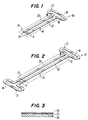
- Figure 1 illustrates one embodiment of heating device 10 of the present invention made from metal foil laminated to paperboard.
- Heating device 10 is preferably designed to be included in a food package.
- Device 10 includes a folded-dipole antenna 12 and transmission portion 14 which includes a surface heating zone 15 located spaced away from antenna 12.
- a food item may be placed directly on transmission portion 14 or at least in close proximity thereto.
- the size and shape of surface heating zone 15 is, therefore, dependent upon the size and shape of the food item.
- the dashed lines used to represent surface heating zone 15 in the Figures are merely provided as an approximation of many possible surface heating zone dimensions which are separate from the microwave capturing antenna.
- antenna 12 is shaped to capture microwave energy in regions away from the foodstuff and transmission portion 14 enhances the effectiveness of this energy by efficiently transferring it to a food item in surface heating zone 15.
- Antenna 12 and transmission portion 14 are made from a conductive material, such as metal foil, as shown in Figure 1, conductive ink or metal wire. These materials provided are merely examples of appropriate materials to be used for these components and should not be considered exhaustive of the possible materials suitable for the present invention.
- antenna 12 and transmission portion 14 are also carefully impedance matched to allow the coupling of large amounts of radiation to the surface of the food item.
- antenna 12 is a folded dipole. Specifically, as shown in Figures 1, 2 and 4-6, antenna 12 includes a tight, elongated loop 16 of conductive material having a narrow gap 18 in the middle of one side. For optimal performance, the length of the antenna is preferably approximately 0.48 of a wavelength or 5.875 cm. Transmission portion 14 is a parallel run of two transmission members 20 and 22 which are generally made from the same material as antenna 12.
- a dipole is a pair of equal length, collinear conductors separated by a short gap.
- the antenna terminals are on the opposite sides of the gap. If the total length of the dipole, represented as L, is maintained small compared to the electromagnetic wavelength produced within the microwave oven wherein the wavelength, ⁇ , is approximately 12.24 cm, and a randomly-polarized, isotropic pattern of radiation is incoming, the dipole intercepts an amount of power equal to that power incident on a surface area of ⁇ 2 /4. Therefore, the amount of power should be independent of the length of the antenna.
- the directivity of the dipole increases with length, and therefore, in order to avoid large sensitivity of the power absorption to oven placement, it is desirable to keep the dipole relatively short.
- the impedance For lengths significantly less than ⁇ /2, the impedance has a large capacitive component and for lengths between ⁇ /2 and ⁇ , the inductive part can be large. At about .48 ⁇ the reactive component is zero, and the antenna impedance is real (about 73 Ohms). To avoid reflection at the terminals of the antenna and the concomitant re-radiation of the energy by the antenna, the antenna impedance should match the impedance of the transmission portion. This means that the impedance of the antenna should be near the complex conjugate of the transmission portion impedance. Simple transmission lines have real impedances (no inductive or capacitive components). Therefore, to avoid complex reactive matching networks, a straightforward approach is to use a .48 ⁇ (5.875 cm) dipole and 73 Ohm transmission line or portion.
- FIG 2 illustrates a second embodiment of heating device 10 wherein antennas 12 are provided at each end of transmission portion 14. This provides increased microwave intensity in transmission portion 14 and ultimately to the surface of the food item. Such a design produces long heating or grill marks on a food item held in close proximity thereto. Specifically, each of the antennas capture microwave energy so that it may be transferred down transmission portion 14 to surface heating zone 15. Further, the endless loop configuration in Figure 2 alleviates the potential for arcing present at ends 19 in the configuration shown in Figure 1.
- Figure 3 shows a cross-sectional view of one method of forming heating device 10 of Figures 1 and 2.
- layer 24 represents aluminum foil which is initially laminated to a rigid substrate 26.
- Layer 24 is fixed by a laminating adhesive 25 to substrate 26.
- a laminating adhesive is disclosed in Figure 3, any conventional means of attaching layer 24 to substrate 26 would be acceptable.
- Substrate 26 should be at least semi-rigid to maintain the integrity of heating device 10.
- substrate 26 comprises paper or paperboard, such as a paperboard food carton or container.
- Heating device 10 is then formed by die cutting layer 24 and substrate 26 into the desired shape, such as those illustrated in Figures 1 and 2.
- a heating device designed in such a manner provides a cost effective microwave heater which can be mass produced and disposable with a food package after use.
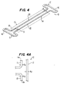
- FIG. 4 illustrates yet another embodiment of the present invention wherein heating device 10 is made from a conductive metal wire.
- heating device 10 would be at least insertable into a food package and in this embodiment could be removed from the package and placed with the antenna away from and the heating portion against the foodstuff to provide a surface heating zone for a food item originally contained in the microwave food carton or package.
- the transmission portion 14 is preferably integral with the surface of a food carton or package and includes parallel transmission members 20 and 22.
- antenna 12 will be assumed to be made from conductive cylindrical wire material, as depicted in Figure 4.
- the impedance of the .48 ⁇ dipole wire antenna can be multiplied by "folding".
- the configuration of the folded-dipole is best understood with reference to Figure 4A in which the folded-dipole has collinear legs 11 and 13 electrically connected at their respective ends 11e and 13e to folded section 17, which is parallel to legs 11 and 13.
- the impedance of the antenna can be estimated by multiplying 73 Ohms by a factor determined from charts, such as the step-up transmission chart for a folded dipole, as provided in Figures 4-19 from the Antenna Engineering Handbook , 2nd Edition, by Richard C. Johnson and Henry Jasik, McGraw Hill, 1961.
- the impedance of the antenna is closely matched to the impedance of the transmission portion.
- the effective radius of a thin, flat conductor is 1/4 its width. Therefore, the y-axis of the chart should be changed to the center separation divided by four times the width of the dipole.
- D/w For effective separation of transmission members 20 and 22, D/w must exceed 1. Therefore, the minimum impedance of this type of line is 120 cosh -1 (2) or about 160 Ohms.
- Antenna 12 and transmission portion 14 must be made of a highly conductive material. If these lines are too resistive, significant amounts of energy will be lost in the reception and transmission phases, and the system will not function properly.
- Aluminum foil is sufficiently conductive for purposes of the present invention. Nonetheless, it might be desirable to use conductive inks or conductive wire instead.
- the present invention should not be limited to the conductive materials specifically described herein, but should include any material that is sufficiently conductive to provide transmission of electromagnetic waves.
- the total end-to-end resistance of members 20 and 22 should preferably be small compared to Z pl .
- the skin depth, ⁇ , of the electrical currents into good conductors is of the order of microns, and, since ⁇ may be less than the thickness of the transmission member, t, all of the transmission member may not be available for charge transfer. Therefore, the resistance (RT) of the total transmission member should preferably be taken as the greater of LT/ ⁇ 2w ⁇ and LT/ ⁇ wt, where ⁇ is the transmission member bulk conductivity, LT is the total transmission member length, and w is the width of the transmission member.
- the conditions for an acceptable conductive material in the mks system are that ⁇ > [50LT/wZ pl ] 2 , and ⁇ > LT/wtZ pl
- the heating of a food item by device 10 is actually accomplished by increased electromagnetic fields near transmission members 20 and 22 due to power transmission.
- An analysis of the electromagnetic fields surrounding at least one of the transmission members of heating device 10 of Figure 4 may be helpful to an understanding of the present invention.
- transmission members 20 with a radius, r, embedded in a dielectric material of permittivity, ⁇ , and a center separation, D
- the fundamental, traveling wave field distributions associated with open transmission lines are transverse electromagnetic (TEM) waves. Therefore, a TEM solution that satisfies the boundary conditions imposed by a round wire in an infinite dielectric is important.
- TEM transverse electromagnetic
- the dielectric power dissipation per unit volume, D v is equal to the real part of E o J*, where J* is the current density.
- the inverse of k" is called the penetration depth of the dielectric, namely, it is the distance a plane wave propagates into the dielectric before its amplitude drops by a factor of 1/e.
- the important things to note from Eqn. (9) are: (a) the power dissipation intensity increases as 1/r 2 as you approach transmission number 20; (b) loss is proportional to the imaginary part of the dielectric constant; and (c) the wave is attenuated in the z-direction at the same exponential rate as plane wave radiation in the dielectric. In the real microwave oven, where transmission member 20 is placed on the food (not imbedded in it), the penetration depth should be approximately twice as great.
- the length of transmission members 20 and 22 is also important for a single antenna, as illustrated in Figure 1. Electrically, the unterminated end of the transmission members is almost an open, in that nearly all the energy arriving is reflected and the phase shift of the reflected E-field is small. A large portion of the radiation striking antenna 12 from transmission members 20 and 22 is also returned thereto. The phase shift of this antenna-returned radiation should be somewhat near 0°. All these multiple end-reflections will interfere along the transmission member. Depending on the length of the member, this interference can be constructive or destructive. Constructive interference causes regions of high electric field to be generated at half-wavelength intervals along the transmission member. If the transmission member is just the right length (or an integer number of half wavelength longer or shorter), these high field regions will be very intense.
- transmission member length is altered by a quarter wavelength, the interference is destructive, and large, localized fields do not develop.
- a resonant length of transmission members 20 and 22 in an empty oven can lead to very large field strengths near the ends of the transmission members and at every half wavelength spacing. This exacerbates any tendency to arc, and if the line is mounted on a lossy dielectric substrate such as paperboard, intense, half-wavelength spaced charring of the substrate can occur in an empty oven.
- Transmission members of odd quarter wavelength connected to a folded-dipole are near resonance and members of even quarter wavelength are near antiresonance.
- transmission portion 14 should include even quarter-wavelength transmission members.
- Device 10 may also include a resistive element 27 to directly convert the collected microwave energy into heat.
- the resistive element 27 may be integral with the end of the transmission portion (series) or bridge the transmission members 20 and 22 (parallel).
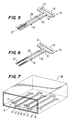
- Figure 5 illustrates the resistive element 27 attached to transmission members 20 and 22 in parallel
- Figure 6 illustrates resistive element 27 in series.
- Resistive element 27 may be made from any material which is capable of heating under the application of electrical current.
- resistive element 27 is made from a conductive ink which can be applied across transmission members 20 and 22 for a parallel connection or the conductivity of the material composing transmission members 20 and 22 can be decreased at points where heating is desired for series relationship.
- FIG 7 illustrates the preferred environment of heating device 10 in a food carton 28.
- a plurality of heating devices 10 are arranged on the bottom of paperboard carton 28.
- heating devices 10 have alternating lengths to avoid interference between the antennas 12 of each of the adjacent devices.
- the heating devices may be made from die cut aluminum foil board, as in Figure 2, and laminated directly to the bottom of carton 28 or the heating devices may constitute separable members, such as illustrated in Figure 3, so that each device is adhered to its own rigid substrate and then integrally attached to carton 28.
- heating devices 10 integral with a food carton
- food stored within the carton can also be cooked therein.
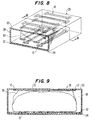
- Figure 8 illustrates such an arrangement wherein a plurality of heating devices 10 are arranged on both the top wall 33 and the bottom wall 34 of the carton 28.
- heating devices 10 may also be arranged on the sides of carton 28 to provide enhanced heating of the side of food item 30 if so desired.
- heating devices which include a separate antenna 12 for capturing microwave energy in the microwave oven cavity, problems associated with "shielding" by heating devices located on opposite sides of food item 30 in conventional, one-source ovens is virtually eliminated by heating device 10 of the present invention.
- Figure 9 provides a cross-sectional view of the carton 28 arrangement of Figure 8 taken along lines 9-9. It is clear in this view that both the top and the bottom surfaces of food item 30 will experience enhanced grilling, crisping, or browning due to the position of heating devices 10. In addition, many food items, such as hamburgers, expel a large amount of juices during cooking. If too much liquid is permitted to pool up in the bottom of carton 28, there will no longer be sufficient contact between the lower surface of food item 30 and heating devices 10. Contact between the surface of the food item and heating device 10 is very important. Also, the food item will not dry sufficiently to permit the formation of grill marks. Therefore, in order to wick these juices away from the surface of the food item, an absorbent layer 32 may be provided below heating devices 10 and the bottom wall 34. Absorbent layer 32 may be made from any conventional absorbent paper, such as, but not limited to, "601b WF waterleaf" produced by James River Corporation in Parchment, Michigan.
- the food item may suspended upon the heating device to permit the juices to fall below the food surface, such as a raised tray including holes to remove excess liquid from the lower food surface.
- This arrangement will also prevent unwanted juices from escaping the carton within the oven cavity. Without such absorbency or liquid removal, the integrity of carton 28 could also be jeopardized by the excessive juices breaking down the paperboard food carton and preventing easy removal from the oven after cooking.
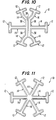
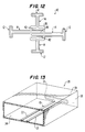
- Figures 10-12 show additional embodiments of the present invention for capturing heat from one portion of the microwave oven and transferring the energy to the surface of a food item to be grilled, crisped or browned.
- Figure 10 illustrates heating device 10 including a plurality of antennas 12 and transmission portions 14. Each of the transmission members of transmission portion 14 are joined to an adjacent transmission portion by at least a small joining section 36 or directly thereto, as in the upper and lower pair of antennas shown in Figure 10.
- a central transmission member 38 is provided for connecting the upper and lower pair of antennas.
- FIG 11 illustrates a second embodiment of heating device 10 including a plurality of antennas 12 and transmission portions 14 wherein each of the transmission members of portions 14 are joined to a transmission member of an adjacent transmission portion 14.
- Figure 12 illustrates a third embodiment of heating device 10 including four antennas 12 and corresponding transmission portions 14 wherein transmission portions 14 terminate in a grill structure 40 centrally located among the plurality of antennas. Portions of the transmission members of transmission portion 14 may actually enter the grill structure 40 to form a portion of the grill, as shown at grill sections 42, or exit through the opposite side thereof to form a corresponding transmission member for the opposing transmission portion, as shown at grill section 44.
- These unique embodiments further enhance the amount of microwave energy captured by the antennas and ultimately directed to a food item being crisped or grilled.
- the food item is placed on transmission members 20, 22 such that antenna 12 is located outside of the food item to enable the antenna to capture microwave energy and ultimately direct it to the food item.
- the food item may be so large that it covers a majority of the bottom wall 34.
- carton 28 may be designed, as illustrated in Figure 13, such that antenna 12 extends out of the plane in which the transmission members lie, for example, onto side walls 38 to allow the folded-dipole antenna to properly capture the microwave energy.
- a heating device 10 having both a single antenna 12 and double antennas 12 can be used.
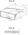
- carton 28 may include another heating element in combination with heating device 10.
- First heating element 60 located adjacent transmission members 20, 22 and positioned on bottom wall 34 of carton 28.
- First heating element 60 is, preferably, a laminate which includes a microwave interactive layer 62 formed on a film 64
- the microwave interactive material is preferably positioned between film 64 and a rigid substrate 46, such as paperboard.
- Figure 15 illustrates the preferred laminate.
- the microwave interactive layer 62 is a thin layer of material which generates heat in response to microwave energy, unless treated to reduce or eliminate this capability.
- microwave responsive is defined to relate to both heating device 10 and heating element 60
- microwave interactive is defined to relate to heating element 60 comprising a layer of microwave interactive material capable of generating heat in response to microwave energy, described in greater detail below.
- the microwave interactive layer 62 may be applied to or deposited on film 62 in a number of methods known in the art, including vacuum vapor deposition, sputtering, printing and the like. Vacuum vapor deposition techniques are preferred.
- the microwave interactive layer 62 may be any suitable lossy material that will generate heat in response to microwave energy.
- Preferred microwave interactive materials useful in forming layer 62 include compositions containing metals or other materials, such as aluminum, iron, nickel, copper, silver, stainless steel, chrome, magnetite, zinc, tin, iron, tungsten and titanium. Some carbon-containing composition are also suitable for this purpose. These materials can be used alone or in combination, and the composition selected may be used in powder, flakes, or fine particles.
- the film layer 64 functions both as a base on which the microwave interactive layer 62 is deposited and as a barrier to separate the food item from the microwave interactive layer 62.
- the film layer 64 must be sufficiently stable at high temperatures suitable for cooking the food item.
- Film layer 64 may be formed from a variety of stable plastic films, including those made from polyesters, polyolefins, nylon, cellophane and polysulfones.
- first microwave heating element 60 By placing first microwave heating element 60 adjacent heating device 10 on transmission members 20, 22, the heating effect of element 60 is given a boost to thereby provide increased or enhanced generation of heat in response to microwave energy.
- food items which require more heat than that which is provided by a conventional heating element 60 and also requires a larger area of surface heating than can be provided by heating device 10, can be adequately heated and cooked in a microwave oven using carton 28 designed in accordance with the embodiment of Figure 14.
- FIG. 16 shows carton 28 including first heating element 60' on bottom wall 34.
- heating device 10 includes two antennas positioned on opposing side walls 38.
- a single antenna could also possibly be used.
- first heating element 60' is three-dimensionally shaped into a container to cradle a food item, such as a pot pie, so that the bottom and side surfaces of the food item are in heat transfer relationship with film 64.
- a container can be formed by any conventional process, such as, for example deep drawing.
- Carton 28 may also include a second heating element 48 located on top wall 33.
- Heating element 48 is similar to first heating element 60.
- heating element 48 may also be selectively deactivated in a predetermined pattern, such that some areas are treated to reduce or eliminate the microwave material's ability to generate heat. Reduction or elimination of the heat generating capability of the microwave interactive material in heating element 48 may be accomplished by a wide variety of methods, such as, for example, demetallization described in US - A - 4,398,994; chemical deactivation described in US - A - 4,865,921 or an abrasion process described in US - A - 4,908,246.
- the heating capacity of various portions thereof can be selectively reduced or eliminated to modify its heating characteristics.
- patterns are also available, as described in US - A - 4,883,936, such as a grid pattern shown in Figure 17, wherein first areas 50 of reduced interactivity are surrounded by a grid of second areas 52 having unaltered capability. Utilizing this second heating element 48 permits the heating and browning of the top surface of a food item held within first heating element 60' without detracting from the enhanced heating provided by first heating element 60'.
- a microwave responsive heating device formed in accordance with the present invention has particular utility in microwave food packaging.
- the microwave responsive heating device of the present invention provides an economically feasible device for enhancing the heating of the surface of a food item which is designed to be an integral part of a disposable food package.
- a package designed to include heating devices of the present invention permits the microwave cooking of food items which have heretofore been unacceptable for microwave cooking by capturing microwave energy in one portion of a microwave oven and transferring it to the food surface in a different portion of the oven to crisp or grill the surface thereof.
Landscapes
- Engineering & Computer Science (AREA)
- Life Sciences & Earth Sciences (AREA)
- Food Science & Technology (AREA)
- Mechanical Engineering (AREA)
- Physics & Mathematics (AREA)
- Electromagnetism (AREA)
- Cookers (AREA)
- Constitution Of High-Frequency Heating (AREA)
- Package Specialized In Special Use (AREA)
- General Preparation And Processing Of Foods (AREA)
- Food Preservation Except Freezing, Refrigeration, And Drying (AREA)
Description
- This invention generally relates to the production of microwave oven cooking elements useful both for food packaging, as well as in reusable utensils and specifically, to the production of microwave cooking elements which are capable of capturing and transferring microwave energy to the surface of a food item to be cooked in a microwave oven. In particular, the present invention relates to a heating device with the features of the preamble of claim 1 as well as a carton according to the preamble of
claim 18. - The popularity of microwave ovens for cooking all or part of a meal has led to the development of a large number of food packages capable of cooking a food item in a microwave oven directly in the food package in which it is stored. The convenience of cooking food in its own package or a component thereof appeals to a large number of consumers. Further, many fast food restaurants are looking to fast, yet effective, ways of cooking and warming food which is less expensive than currently used methods. However, one dissatisfaction of microwave cooking for some foods is the inability to brown the food. It is often difficult to obtain grilling, browning and crisping of certain types of food in a microwave oven.
- US - A - 4,320,274, which forms the starting point of the present invention, discloses a heating device as mentioned above. This known heating device comprises dipole antennas, located in handle grips or side walls, and a bottom wall conductor pattern. Thus, energy from electromagnetic fields within an oven cavity can be coupled to the bottom wall for realising a more uniform heating of food. This device is not suitable for effectively grilling or browning the surface of the food.
- Microwave interactive films have been produced which are capable of generating heat at the food surface to crispen some food products. US - A - 4,883,936 discloses the production of a microwave interactive heating element for food packaging which is selectively deactivated to provide an area or areas of microwave interactive material and an area or areas of deactivated material in a pattern on the surface of the heating element, so that only the area or areas having the interactive material untreated are fully capable of generating heat. Specifically, the patterned, deactivated heating element can be used to selectively brown the surface of a food item. Unfortunately, some food items, particularly very thick or solid foods, such as chicken fillets, absorb such a large portion of microwave radiation that the crisping element does not intercept sufficient energy for the desired browning and crisping at the surface of such a food item.
- Other devices have also been developed to brown the surface of a food item in a microwave oven. US - A - 3,591,751 discloses a browning apparatus for use in a microwave oven. Specifically, the apparatus includes microwave coupling devices located in contact or in close proximity to a food item for the purpose of browning. The coupling devices may be a plurality of metal rods supported on a dielectric board. The length of the rods themselves are integer multiples of a half wavelength with respect to the frequency of the microwave source to cause a resonant increase in the microwave currents on the surface of the rods. A separate apparatus may be used on both the top and the bottom of the food item to attempt to brown both sides thereof. However, using conventional single source microwave ovens in which the microwave source is located near the top of the oven cavity, more browning is observed on the top surface of the food than on the bottom surface of the food due to "shadowing" by the rods of the device on the top. A similar result in reverse holds true for microwave ovens in which the microwave source is located only near the bottom. US - A - 3,591,751 providing two microwave source feeds located near the top and the bottom of the oven or a coupler to provide dual feeds. However, because conventional microwaves used by most consumers today only include a single microwave source near the top of the oven, this "shadowing" effect would occur while using the apparatus disclosed in US - A - 3,591,751 and therefore, would not be suitable for mass produced consumer use. Moreover, this apparatus is a large separate appliance type device and is, therefore, not contemplated to be used for food packaging.
- US - A - 3,946,187 discloses another example of a microwave browning or searing utensil for use in a microwave oven. The device is provided with a plurality of conductive metal members each of which are folded in such a manner to provide a continuous apex and two substantially equidistant legs. The legs are substantially one-quarter of a wavelength in height. Microwaves irradiated within the oven are converted by the array of conductive members to provide an intense fringing electric field in close proximity to a food item being heated thereon. The utensil may rest upon the floor of the oven cavity and may also be supported on top of a food load, as in US - A - 3,591,751. Again, however, while use of upper and lower utensils are suggested, there is no means for directing the microwave energy to both utensils disclosed in US - A - 3,946,187, so the effects of "shadowing," discussed above, may still present a problem. Moreover, the device disclosed in US - A - 3,946,187 is a separate utensil which is not designed to be disposable, as in popular microwave food packaging.
- Devices have also been developed for providing uniform heating by microwave energy at desired points within an area of the microwave oven cavity. US - A - 3,271,552 discloses a microwave heating apparatus which includes small antennas or supplemental radiating elements, which are preferably screwed into threaded holes provided in a portion of a wall of the microwave oven, to apply concentrated microwave energy to a food item. US - A - 3,271,552 also discloses the use of conductive strips which may be secured to and form a part of a food package. Specifically, the strips may be present as aluminum foil strips or rods. These elements do not, however, contact a food item nor provide browning or crisping thereof. Rather, the elements merely concentrate existing microwave energy which is present in the oven cavity.
- US - A - 4,992,636 discloses a sealed container for microwave oven cooking wherein a lid is partially melted by microwave energy to form an opening therein. Specifically, the lid includes an antenna made of an electrically conductive material which concentrates microwave energy at a position near the front of the antenna and converts this energy to heat in order to melt a portion of the lid. However, the antenna does not provide a browning or crisping effect on food held within the container.
- Some antennas have been developed which are useful for efficiently distributing heat within the interior of a food product, such as a turkey. US - A - 4,460,814 discloses an oven antenna probe for distributing energy in a microwave oven. Specifically, the antenna probe is designed to be inserted into a food item to distribute microwave energy within the food to provide adequate cooking inside and outside. The antenna includes a source end antenna element which delivers power to a load end configured as a probe for insertion into the food.
- Several of the antenna-like structures may also be positioned throughout the oven cavity for reradiating energy towards a food product. The antennas do not, however, provide a sufficient amount of energy concentration to brown the surface of a food item, but rather redistribute the energy within the oven cavity to effectively cook a food item so that a similar amount of heating occurs at the center of a food item as at the outer portion of the food.
- US - A - 4,866,234 and US - A - 4,888,459 disclose a microwave container which redistributes heat in a microwave oven to avoid "cold spots" which are commonly found within a microwave oven cavity. Specifically, the container may include a two-dimensional antenna or a slot antenna for receiving microwave energy in the oven cavity and to create a microwave field pattern or to act as a window for microwave energy, respectively. Again, these "antennas" do not provide a sufficient amount of concentrated or enhanced microwave energy near a food item to brown or grill the surface thereof.
- Furthermore, US - A - 4,816,634 discloses a method and apparatus for measuring strong microwave electric field strengths. Moreover, this patent, as well as US - A - 4,934,829 disclose the use of cylindrical wave guides for cooking multi-component, layered food items. These disclosures are primarily directed to test probes or strips and do not provide a means of capturing and transferring energy in a microwave oven.
- Consequently, a microwave oven heating device is needed which effectively captures microwave energy present in an oven cavity and transmits it to the surface of a food item which is conventionally browned or grilled. Further, a device is needed for heating or grilling food items in conventional, one source microwave ovens which can be included in disposable microwave food packaging or in reusable utensils.
- Object of the present invention is to provide a heating device and a carton for cooking a food item in a microwave oven with more effectively grilling or browning of the surface of the food item.
- The above object is achieved by a heating device according to claim 1 and a carton according to
claim 18, respectively. Preferred embodiments are subject of the subclaims. - An advantage of the present invention is to overcome the deficiencies of the prior art, as described above, and specifically, to provide a microwave responsive heating device to receive and transfer enhanced energy to the surface of a food item to effectively heat the surface thereof.
- Another advantage of the present invention is to provide a microwave responsive heating device for microwave food packaging which effectively operates in a conventional, one source microwave oven.
- Yet another advantage of the present invention is to provide a microwave responsive heating device suitable either for use in a reusable utensil or for insertion into a carton for storing and cooking a food item in a microwave oven to provide a commercially appealing disposable food container wherein the device captures microwave energy in the microwave oven and transmits the energy in a concentrated form to crisp or grill a surface of a food item held within the carton.
- Still another advantage of the present invention is to provide a microwave responsive heating device which includes an antenna member to capture microwave energy and a transmission portion to transmit the energy to the surface of a food item in a concentrated or enhanced form.
- Yet another advantage of the present invention is to provide a microwave responsive heating device which includes an antenna member shaped to efficiently capture microwave energy in one area of a microwave oven and a transmission portion shaped to efficiently transmit that energy to the surface of a food item in another area of the oven wherein the energy supplied to the food item from the transmission portion is sufficiently enhanced to crisp or grill the surface of the food item.
- Still another advantage of the present invention is to provide a microwave responsive heating device which includes an antenna member shaped to efficiently capture microwave energy in one area of a microwave oven away from the food, a transmission portion to transmit the energy and a resistive element to supply heat energy to the surface of a food item in another area of the oven wherein the heat energy supplied to the food item is sufficiently enhanced to crisp or grill the surface of the food item.
- Another advantage of the present invention is to provide a microwave responsive heating device which includes an antenna member shaped to efficiently capture microwave energy in one area of a microwave oven away from the food, a transmission portion to transmit the energy and a microwave interactive means adjacent the transmission portion to supply enhanced heat energy to a food item in heat transfer relationship with the microwave interactive means.
- The foregoing advantages are especially achieved by providing a microwave responsive heating device for capturing microwave energy in a microwave oven and for transmitting the energy to a surface of a food item in a concentrated form to grill, crisp, or brown the surface thereof. The heating device includes an antenna for collecting the microwave energy and a transmission portion for transferring the collected energy from the antenna to a surface heating zone, separate from the antenna, to heat the surface of the food item. Preferably, the heating device is designed to be integral with the interior portions of a food package to allow a food item to be stored and cooked within the food package. The antenna and the transmission portion are made from electrically conductive materials and are shaped to not only capture and transmit microwave energy, but also to enhance the intensity of the microwave energy. The present invention provides a commercially feasible device useful in food packaging for heating and/or browning food items that are conventionally grilled and have, until now, been inappropriate for microwave cooking.
- In preferred embodiments, the antenna comprises a folded-dipole located away from the food, while in more preferred embodiments, the transmission and heating portions are closely impedance matched to the folded-dipole. In the most preferred embodiments, the heating device will comprise at least one endless loop, ideally having two or more folded-dipoles arranged in a compact array spaced away from but surrounding the foodstuff, the array being connected to transmission means leading to heating means adjacent the surface to be grilled, crisped, or browned. This configuration has been found to be surprisingly effective in capturing energy and transmitting it to the heating portion while alleviating potential for arcing. In addition, it can be combined with a microwave interactive material to boost the heat generating ability of the microwave interactive material.
- The various features, objects and advantages of the present invention will become apparent from the following Brief Description of the Drawings and Detailed Description of the Invention.
-
- Figure 1 illustrates a microwave heating device including a single folded-dipole antenna of aluminum foil laminated to paperboard;
- Figure 2 illustrates a microwave heating device including a double folded-dipole antenna constituting an endless loop;
- Figure 3 illustrates a cross-section of one embodiment of the present invention including a rigid support layer and a layer of aluminum foil adhered thereto;
- Figure 4 illustrates a second embodiment of the present invention wherein the microwave heating device comprises metal wire;
- Figure 4A illustrates a portion of the folded-dipole antenna of the present invention;
- Figure 5 illustrates a portion of a microwave heating device including a resistive element located between the members of the transmission portion thereof in parallel arrangement;
- Figure 6 illustrates a portion of a microwave heating device wherein the transmission members include resistive elements in series arrangement;
- Figure 7 illustrates a food package which includes a plurality of dual-folded-dipole microwave heating devices located on the bottom of the food package;
- Figure 8 illustrates a food package which includes a plurality of dual-folded-dipole microwave heating devices located on the top and the bottom of the package and further includes a food item held therein;
- Figure 9 illustrates the food package of Figure 8 taken along line 9-9;
- Figure 10 illustrates one embodiment of a single heating device including a plurality of antennas and transmission portions;
- Figure 11 illustrates a second embodiment a single dual-endless loop heating device including a plurality of folded-dipole antennas and transmission portions;
- Figure 12 illustrates a third embodiment of a single heating device including a plurality of folded-dipole antennas and transmission portions;
- Figure 13 illustrates a second embodiment of a food package including a single folded-dipole antenna of the present invention;
- Figure 14 illustrates a food package similar to the package shown in Figure 13 further including a microwave interactive portion;
- Figure 15 is a diagrammatic representation of a microwave interactive heating element;
- Figure 16 illustrates another embodiment of a food package including a single folded-dipole antenna of the present invention further including an inner microwave interactive portion which cradles a food item; and
- Figure 17 illustrates a microwave interactive layer deactivated in a grid pattern.
-
- The convenience and speed of microwave cooking has led to ever increasing interest in devices which cook a food item in such a way that it appears and tastes as if it were cooked in a conventional manner. The problem with conventional microwave ovens is that a large number of food items, when heated or cooked therein, do not achieve even a minimally acceptable appearance or taste. Among such food items are conventionally fried or grilled foods, such as fish, chicken, or hamburgers. Devices have been developed to attempt to improve the taste and appearance of such microwave cooked foods, however, these devices, are not particularly effective in conventional one-source microwave ovens. Moreover, the development of food packaging designs which allow the storage and microwave cooking of a food item in the package itself have become very attractive to consumers in recent years. The devices designed thus far for browning or grilling food items are generally separate, bulky devices which are not readily adaptable to food packaging. The present invention provides a device which is effective in grilling and crisping high bulk food items and which is readily adaptable to disposable food packaging.
- For a clearer understanding of the present invention, attention is initially directed to Figure 1. Figure 1 illustrates one embodiment of
heating device 10 of the present invention made from metal foil laminated to paperboard.Heating device 10 is preferably designed to be included in a food package.Device 10 includes a folded-dipole antenna 12 andtransmission portion 14 which includes asurface heating zone 15 located spaced away fromantenna 12. A food item may be placed directly ontransmission portion 14 or at least in close proximity thereto. The size and shape ofsurface heating zone 15 is, therefore, dependent upon the size and shape of the food item. As a result, the dashed lines used to representsurface heating zone 15 in the Figures are merely provided as an approximation of many possible surface heating zone dimensions which are separate from the microwave capturing antenna. - Specifically,
antenna 12 is shaped to capture microwave energy in regions away from the foodstuff andtransmission portion 14 enhances the effectiveness of this energy by efficiently transferring it to a food item insurface heating zone 15.Antenna 12 andtransmission portion 14 are made from a conductive material, such as metal foil, as shown in Figure 1, conductive ink or metal wire. These materials provided are merely examples of appropriate materials to be used for these components and should not be considered exhaustive of the possible materials suitable for the present invention. Moreover, as will be discussed in greater detail below,antenna 12 andtransmission portion 14 are also carefully impedance matched to allow the coupling of large amounts of radiation to the surface of the food item. - Preferably,
antenna 12 is a folded dipole. Specifically, as shown in Figures 1, 2 and 4-6,antenna 12 includes a tight,elongated loop 16 of conductive material having anarrow gap 18 in the middle of one side. For optimal performance, the length of the antenna is preferably approximately 0.48 of a wavelength or 5.875 cm.Transmission portion 14 is a parallel run of twotransmission members antenna 12. - Specifically, addressing
antenna 12, a dipole is a pair of equal length, collinear conductors separated by a short gap. The antenna terminals are on the opposite sides of the gap. If the total length of the dipole, represented as L, is maintained small compared to the electromagnetic wavelength produced within the microwave oven wherein the wavelength, λ, is approximately 12.24 cm, and a randomly-polarized, isotropic pattern of radiation is incoming, the dipole intercepts an amount of power equal to that power incident on a surface area of λ2/4. Therefore, the amount of power should be independent of the length of the antenna. The directivity of the dipole increases with length, and therefore, in order to avoid large sensitivity of the power absorption to oven placement, it is desirable to keep the dipole relatively short. - The important property of the dipole that does change rapidly with L is its impedance. For lengths significantly less than λ/2, the impedance has a large capacitive component and for lengths between λ/2 and λ, the inductive part can be large. At about .48λ the reactive component is zero, and the antenna impedance is real (about 73 Ohms). To avoid reflection at the terminals of the antenna and the concomitant re-radiation of the energy by the antenna, the antenna impedance should match the impedance of the transmission portion. This means that the impedance of the antenna should be near the complex conjugate of the transmission portion impedance. Simple transmission lines have real impedances (no inductive or capacitive components). Therefore, to avoid complex reactive matching networks, a straightforward approach is to use a .48λ (5.875 cm) dipole and 73 Ohm transmission line or portion.
- Figure 2 illustrates a second embodiment of
heating device 10 whereinantennas 12 are provided at each end oftransmission portion 14. This provides increased microwave intensity intransmission portion 14 and ultimately to the surface of the food item. Such a design produces long heating or grill marks on a food item held in close proximity thereto. Specifically, each of the antennas capture microwave energy so that it may be transferred downtransmission portion 14 tosurface heating zone 15. Further, the endless loop configuration in Figure 2 alleviates the potential for arcing present at ends 19 in the configuration shown in Figure 1. - Figure 3 shows a cross-sectional view of one method of forming
heating device 10 of Figures 1 and 2. Specifically,layer 24 represents aluminum foil which is initially laminated to arigid substrate 26.Layer 24 is fixed by alaminating adhesive 25 tosubstrate 26. Although a laminating adhesive is disclosed in Figure 3, any conventional means of attachinglayer 24 tosubstrate 26 would be acceptable.Substrate 26 should be at least semi-rigid to maintain the integrity ofheating device 10. Preferably,substrate 26 comprises paper or paperboard, such as a paperboard food carton or container.Heating device 10 is then formed by die cuttinglayer 24 andsubstrate 26 into the desired shape, such as those illustrated in Figures 1 and 2. A heating device designed in such a manner provides a cost effective microwave heater which can be mass produced and disposable with a food package after use. - Figure 4 illustrates yet another embodiment of the present invention wherein
heating device 10 is made from a conductive metal wire. Preferably,heating device 10 would be at least insertable into a food package and in this embodiment could be removed from the package and placed with the antenna away from and the heating portion against the foodstuff to provide a surface heating zone for a food item originally contained in the microwave food carton or package. - The importance of the "folded-dipole" antenna in the embodiments illustrated in Figures 1, 2 and 4 becomes readily apparent with reference to the discussion below, and due to the fact that the impedance of parallel transmission members, as used in the present invention, commonly have impedances significantly greater than 73 Ohms. The
transmission portion 14 is preferably integral with the surface of a food carton or package and includesparallel transmission members antenna 12 will be assumed to be made from conductive cylindrical wire material, as depicted in Figure 4. The impedance of the .48λ dipole wire antenna can be multiplied by "folding". The configuration of the folded-dipole is best understood with reference to Figure 4A in which the folded-dipole hascollinear legs 11 and 13 electrically connected at theirrespective ends 11e and 13e to foldedsection 17, which is parallel tolegs 11 and 13. By adjusting the radius of thelegs 11 and 13 and the radius of foldedsection 17, the impedance of the antenna can be estimated by multiplying 73 Ohms by a factor determined from charts, such as the step-up transmission chart for a folded dipole, as provided in Figures 4-19 from the Antenna Engineering Handbook, 2nd Edition, by Richard C. Johnson and Henry Jasik, McGraw Hill, 1961. So, by properly adjusting the dimensions of the legs and folded section of the folded-dipole, its impedance can be conveniently selected to any value between 73 ohms and about ten times 73 Ohms. For example, the multiplication factor is 4 when two wires have the same radius, while it becomes greater than 4 when the folded section is fatter. In preferred embodiments, the impedance of the antenna is closely matched to the impedance of the transmission portion. Parallel, round wire transmission lines or members have an impedance of:transmission members antenna 12. Therefore, for folded-dipoles having legs 11 and 13, respectively, and foldedsections 17 of equal diameters, the center separation D of the transmission members divided by the diameter d of the round wire in the transmission members, as illustrated in Figure 4, is found from 4·(73) = 120·cosh-1(D/d) or D/d = 5.7. - For flat line or planar antenna calculations, the effective radius of a thin, flat conductor, as shown in Figures 1, 2, 5 and 6, is 1/4 its width. Therefore, the y-axis of the chart should be changed to the center separation divided by four times the width of the dipole. The impedance of this planar transmission portion is:
transmission members dipole antenna 12 is important for effective utilization of the present invention in a food packaging environment. So, in a particular design, the parameters of the 5.875 cm folded-dipole antenna must be chosen so that the impedance determined from the chart referred to above equals that of thetransmission members dipole antenna 12, as illustrated in Figures 1 and 2, the relationship of the center separation over the width is 4 · (73) = 120 · cosh-1 (2D/w) or D/w = 2.85. -
Antenna 12 andtransmission portion 14 must be made of a highly conductive material. If these lines are too resistive, significant amounts of energy will be lost in the reception and transmission phases, and the system will not function properly. Aluminum foil is sufficiently conductive for purposes of the present invention. Nonetheless, it might be desirable to use conductive inks or conductive wire instead. In view thereof, the present invention should not be limited to the conductive materials specifically described herein, but should include any material that is sufficiently conductive to provide transmission of electromagnetic waves. - For the ohmic losses in
antenna 12 andtransmission members members - For example, take a conductive ink in the mid range of available silver-based polymer films (σ = 5x10⁵ 1/mOhm) and allow a 5% loss of energy in transmission. If t = 2δ, effective use of the conductive ink is possible, and Eqn. (3) and (4) are equivalent. So if t is 28 µm, this ink is acceptable if LT/wZpl is less than 0.7/Ohm.
- The heating of a food item by
device 10 is actually accomplished by increased electromagnetic fields neartransmission members heating device 10 of Figure 4 may be helpful to an understanding of the present invention. Assumingtransmission members 20, with a radius, r, embedded in a dielectric material of permittivity, ε, and a center separation, D, the z-axis of a cylindrical coordinate system can be aligned withtransmission member 20 to consider the losses therefrom out to a distance of r=D/2, ignoring the fields generated bytransmission member 22. The fundamental, traveling wave field distributions associated with open transmission lines are transverse electromagnetic (TEM) waves. Therefore, a TEM solution that satisfies the boundary conditions imposed by a round wire in an infinite dielectric is important. - Using the conventional form for sinusoidal times dependence (eiωt), the z-direction dependence of a forward-traveling, TEM wave is e-ikz, where k2 is µε (the permeability times the permittivity of the surrounding dielectric). The Cartesian components of the transverse E-field of a TEM wave must satisfy Laplace's equation. This means that ▿2Ex = ▿2Ey = 0, where the differential operator is only in the transverse plane. A traveling wave solution to the transverse Laplace's equation having cylindrical symmetry and meeting the boundary condition that E = 0 at r=a, is
- The current, I, in
transmission member 20 can be related to the fields by Stokes's equation for the H-field. That is, a line integral of the H-field around a circleenclosing transmission member 20 equals the current, or - In view thereof, the dielectric power dissipation per unit volume, Dv, is equal to the real part of EoJ*, where J* is the current density. The only current in the dielectric is the displacement current, so J = iωD = iωεE. As a result, the per unit volume power dissipation then becomes
transmission number 20; (b) loss is proportional to the imaginary part of the dielectric constant; and (c) the wave is attenuated in the z-direction at the same exponential rate as plane wave radiation in the dielectric. In the real microwave oven, wheretransmission member 20 is placed on the food (not imbedded in it), the penetration depth should be approximately twice as great. So, iftransmission member 20 carrying current passes over a food item, the surface intensified cooking will persist about twice as far as free space radiation normally penetrates into the food. The 2.45GHz penetration depth of most foods is about 2 cm. Therefore, it is expected that energy received fromantenna 12 and traveling downtransmission portion 14 will intensify cooking for about two inches after the initial food-line intersection. As the food cooks and dries, the penetration depth will increase, and the heating will progress somewhat downtransmission portion 14. - The power absorbed per unit length, D1, is derived by integrating 2πrDv over r from a to D/2. To get an estimate of the contribution of each transmission member, the single transmission member electromagnetic field is cut off at the midpoint of the two members. The result is
- There is also some heat dissipated directly in the transmission member. Assuming the radius of
transmission member 20 is much greater than one skin depth, δ, in radius, the effective resistance, R, of a round wire per unit length is approximately 1/(2πaδσ), where σ is the bulk electrical conductivity of the wire. The power (Dw) generated in the wire per unit length is the real part of IRI*. Substituting I from Eqn. (9), writing the skin depth in terms of more basic parameters (δ = [2/ωµσ]½), and using Z = (µ/ε)½, provides the following expression for Dw:transmission member transmission members transmission portion 14 having transmission members of any reasonable diameter, so that losses from currents in a 1 mil. (25.4 µm) thick aluminum foil should also be similarly in the dielectric regime. - The length of
transmission members radiation striking antenna 12 fromtransmission members transmission portion 14, this does not have as much significance, since most of the energy will be lost on the first pass overtransmission members transmission members transmission portion 14 should include even quarter-wavelength transmission members. -
Device 10 may also include aresistive element 27 to directly convert the collected microwave energy into heat. Theresistive element 27 may be integral with the end of the transmission portion (series) or bridge thetransmission members 20 and 22 (parallel). Figure 5 illustrates theresistive element 27 attached totransmission members resistive element 27 in series.Resistive element 27 may be made from any material which is capable of heating under the application of electrical current. Preferably,resistive element 27 is made from a conductive ink which can be applied acrosstransmission members transmission members resistive element 27 produces excessive heating is some circumstances, making its use inappropriate for some food items. - Figure 7 illustrates the preferred environment of
heating device 10 in afood carton 28. Specifically, as shown in the Figure, a plurality ofheating devices 10 are arranged on the bottom ofpaperboard carton 28. Preferably,heating devices 10 have alternating lengths to avoid interference between theantennas 12 of each of the adjacent devices. The heating devices may be made from die cut aluminum foil board, as in Figure 2, and laminated directly to the bottom ofcarton 28 or the heating devices may constitute separable members, such as illustrated in Figure 3, so that each device is adhered to its own rigid substrate and then integrally attached tocarton 28. - By providing
heating devices 10 integral with a food carton, food stored within the carton can also be cooked therein. Figure 8 illustrates such an arrangement wherein a plurality ofheating devices 10 are arranged on both thetop wall 33 and thebottom wall 34 of thecarton 28. Such an arrangement will allow the enhanced heating of both sides offood item 30 contained withincarton 28. Although not shown,heating devices 10 may also be arranged on the sides ofcarton 28 to provide enhanced heating of the side offood item 30 if so desired. By providing heating devices which include aseparate antenna 12 for capturing microwave energy in the microwave oven cavity, problems associated with "shielding" by heating devices located on opposite sides offood item 30 in conventional, one-source ovens is virtually eliminated byheating device 10 of the present invention. - Figure 9 provides a cross-sectional view of the
carton 28 arrangement of Figure 8 taken along lines 9-9. It is clear in this view that both the top and the bottom surfaces offood item 30 will experience enhanced grilling, crisping, or browning due to the position ofheating devices 10. In addition, many food items, such as hamburgers, expel a large amount of juices during cooking. If too much liquid is permitted to pool up in the bottom ofcarton 28, there will no longer be sufficient contact between the lower surface offood item 30 andheating devices 10. Contact between the surface of the food item andheating device 10 is very important. Also, the food item will not dry sufficiently to permit the formation of grill marks. Therefore, in order to wick these juices away from the surface of the food item, anabsorbent layer 32 may be provided belowheating devices 10 and thebottom wall 34.Absorbent layer 32 may be made from any conventional absorbent paper, such as, but not limited to, "601b WF waterleaf" produced by James River Corporation in Parchment, Michigan. - Further, the food item may suspended upon the heating device to permit the juices to fall below the food surface, such as a raised tray including holes to remove excess liquid from the lower food surface. This arrangement will also prevent unwanted juices from escaping the carton within the oven cavity. Without such absorbency or liquid removal, the integrity of
carton 28 could also be jeopardized by the excessive juices breaking down the paperboard food carton and preventing easy removal from the oven after cooking. - Figures 10-12 show additional embodiments of the present invention for capturing heat from one portion of the microwave oven and transferring the energy to the surface of a food item to be grilled, crisped or browned. Specifically, Figure 10 illustrates
heating device 10 including a plurality ofantennas 12 andtransmission portions 14. Each of the transmission members oftransmission portion 14 are joined to an adjacent transmission portion by at least a small joiningsection 36 or directly thereto, as in the upper and lower pair of antennas shown in Figure 10. In addition, acentral transmission member 38 is provided for connecting the upper and lower pair of antennas. - Figure 11 illustrates a second embodiment of
heating device 10 including a plurality ofantennas 12 andtransmission portions 14 wherein each of the transmission members ofportions 14 are joined to a transmission member of anadjacent transmission portion 14. Figure 12 illustrates a third embodiment ofheating device 10 including fourantennas 12 andcorresponding transmission portions 14 whereintransmission portions 14 terminate in a grill structure 40 centrally located among the plurality of antennas. Portions of the transmission members oftransmission portion 14 may actually enter the grill structure 40 to form a portion of the grill, as shown atgrill sections 42, or exit through the opposite side thereof to form a corresponding transmission member for the opposing transmission portion, as shown atgrill section 44. These unique embodiments further enhance the amount of microwave energy captured by the antennas and ultimately directed to a food item being crisped or grilled. Although defined configurations are presented in Figures 10-12, numerous additional configurations are also contemplated and should fall within the scope of the present invention. - As clearly shown in Figures 7-8, the food item is placed on
transmission members antenna 12 is located outside of the food item to enable the antenna to capture microwave energy and ultimately direct it to the food item. In some cases, the food item may be so large that it covers a majority of thebottom wall 34. As a result,carton 28 may be designed, as illustrated in Figure 13, such thatantenna 12 extends out of the plane in which the transmission members lie, for example, ontoside walls 38 to allow the folded-dipole antenna to properly capture the microwave energy. Aheating device 10 having both asingle antenna 12 anddouble antennas 12 can be used. - In addition,
carton 28 may include another heating element in combination withheating device 10. Specifically, Figure 14 illustrates afirst heating element 60 locatedadjacent transmission members bottom wall 34 ofcarton 28.First heating element 60 is, preferably, a laminate which includes a microwaveinteractive layer 62 formed on afilm 64 The microwave interactive material is preferably positioned betweenfilm 64 and a rigid substrate 46, such as paperboard. Figure 15 illustrates the preferred laminate. The microwaveinteractive layer 62 is a thin layer of material which generates heat in response to microwave energy, unless treated to reduce or eliminate this capability. As used herein, microwave responsive is defined to relate to bothheating device 10 andheating element 60, while microwave interactive is defined to relate toheating element 60 comprising a layer of microwave interactive material capable of generating heat in response to microwave energy, described in greater detail below. - Specifically, the microwave
interactive layer 62 may be applied to or deposited onfilm 62 in a number of methods known in the art, including vacuum vapor deposition, sputtering, printing and the like. Vacuum vapor deposition techniques are preferred. The microwaveinteractive layer 62 may be any suitable lossy material that will generate heat in response to microwave energy. Preferred microwave interactive materials useful in forminglayer 62 include compositions containing metals or other materials, such as aluminum, iron, nickel, copper, silver, stainless steel, chrome, magnetite, zinc, tin, iron, tungsten and titanium. Some carbon-containing composition are also suitable for this purpose. These materials can be used alone or in combination, and the composition selected may be used in powder, flakes, or fine particles. - The
film layer 64 functions both as a base on which the microwaveinteractive layer 62 is deposited and as a barrier to separate the food item from the microwaveinteractive layer 62. Thefilm layer 64 must be sufficiently stable at high temperatures suitable for cooking the food item.Film layer 64 may be formed from a variety of stable plastic films, including those made from polyesters, polyolefins, nylon, cellophane and polysulfones. - By placing first
microwave heating element 60adjacent heating device 10 ontransmission members element 60 is given a boost to thereby provide increased or enhanced generation of heat in response to microwave energy. As a result, food items, which require more heat than that which is provided by aconventional heating element 60 and also requires a larger area of surface heating than can be provided byheating device 10, can be adequately heated and cooked in a microwaveoven using carton 28 designed in accordance with the embodiment of Figure 14. - Many food items, such as pot pies or fruit pies, not only require surface heating or browning of the bottom surface, but also the side and top surfaces. Yet another embodiment of
carton 28 is illustrated in Figure 16. Specifically, Figure 16 showscarton 28 including first heating element 60' onbottom wall 34. In this embodiment,heating device 10 includes two antennas positioned on opposingside walls 38. However, depending upon the degree of microwave energy increase to heating element 60', a single antenna could also possibly be used. - In addition, first heating element 60' is three-dimensionally shaped into a container to cradle a food item, such as a pot pie, so that the bottom and side surfaces of the food item are in heat transfer relationship with
film 64. Such a container can be formed by any conventional process, such as, for example deep drawing. By placing heating element 60' ontransmission members -
Carton 28 may also include asecond heating element 48 located ontop wall 33.Heating element 48 is similar tofirst heating element 60. In addition,heating element 48 may also be selectively deactivated in a predetermined pattern, such that some areas are treated to reduce or eliminate the microwave material's ability to generate heat. Reduction or elimination of the heat generating capability of the microwave interactive material inheating element 48 may be accomplished by a wide variety of methods, such as, for example, demetallization described in US - A - 4,398,994; chemical deactivation described in US - A - 4,865,921 or an abrasion process described in US - A - 4,908,246. - These methods are only a few of the possible methods of deactivating the microwave interactive material of
heating element 48. - By deactivating certain areas of the microwave interactive material in a predetermined pattern, the heating capacity of various portions thereof can be selectively reduced or eliminated to modify its heating characteristics. A variety of patterns are also available, as described in US - A - 4,883,936, such as a grid pattern shown in Figure 17, wherein
first areas 50 of reduced interactivity are surrounded by a grid ofsecond areas 52 having unaltered capability. Utilizing thissecond heating element 48 permits the heating and browning of the top surface of a food item held within first heating element 60' without detracting from the enhanced heating provided by first heating element 60'. - A microwave responsive heating device formed in accordance with the present invention has particular utility in microwave food packaging. In particular, the microwave responsive heating device of the present invention provides an economically feasible device for enhancing the heating of the surface of a food item which is designed to be an integral part of a disposable food package. A package designed to include heating devices of the present invention permits the microwave cooking of food items which have heretofore been unacceptable for microwave cooking by capturing microwave energy in one portion of a microwave oven and transferring it to the food surface in a different portion of the oven to crisp or grill the surface thereof.
- It is understood, however, that various additional changes and modifications in the form and detail of the present invention illustrated in detail above may be made.
Claims (30)
- Microwave responsive heating device (10) for transmitting energy to a food item (30) in a microwave oven by capturing microwave energy in the microwave oven, wherein the heating device (10) comprises an antenna (12) spaced away from the food item (30) for collecting microwave energy, and transmission means for transferring the collected energy to a heating zone (15), which is located separate from the antenna (12), for heating a surface of the food item (30), which is located in close proximity to the heating zone (15), wherein the antenna (12) and the transmission means are formed from electrically conductive materials,
characterized in
that the antenna (12) comprises an antenna loop (16) and that the antenna (12) and the transmission means are impedance matched. - Heating device according to claim 1, characterized in that the antenna (12) and the transmission means are arranged in a folded-dipole configuration.
- Heating device according to any one of the preceding claims, characterized in that the antenna loop (16) is made of electrically conductive material and elongated with a narrow gap (18) of a predetermined distance (D) in the middle of an elongated side thereof.
- Heating device according to claim 3, characterized in that the elongated loop (16) includes a folded section (17) and a pair of collinear leg portions (11, 13) which are spaced apart by the narrow gap (18) and electrically connected to the folded section (17) to form the elongated loop (16).
- Heating device according to any one of the preceding claims, characterized in that the transmission means comprise a pair of parallel members (20, 22) spaced apart by a distance (D) sufficient to cause impedance matching of the antenna (12) and the transmission means.
- Heating device according to claim 1 and, optionally, any other preceding claim, characterized in that the conductive material is a metal wire.
- Heating device according to claims 4 to 6, characterized in that the wire is cylindrical, that the legs (11, 13) and the folded section (17) of the antenna (12) have uniform diameter (d) and wherein the ratio of the distance (D) between the centers of the pair of parallel members and the diameter (d) of the wire is approximately 5,7.
- Heating device according to claim 1 and, optionally, any other preceding claim, characterized in that the conductive material is a metal foil, which preferably comprises aluminium.
- Heating device according to claim 4 and, optionally, any other preceding claim, characterized in that the legs (11, 13) and the folded section (17) of the antenna (12) are of uniform width and that the ratio of the distance (D) between the centers of the pair of parallel members (20, 22) and the width of the parallel members (20, 22) is approximately 2,85.
- Heating device according to claim 1 and, optionally, any other preceding claim, characterized in that the conductive material is conductive ink printed on a dieletric substrate (26), wherein the conductive ink preferably comprises silver.
- Heating device according to any one of the preceding claims, characterized in that the antenna (12) is approximately 0,48 of a microwave wavelength in length.
- Heating device according to any one of the preceding claims, characterized in that the heating device (10) includes a pair of antennas (12) located at opposite ends of the transmission means.
- Heating device according to any one the preceding claims, characterized in that the heating device (10) further includes a resistive element (27) located opposite the antenna (12) along the transmission means for converting microwave energy captured by the antenna (12) into thermal energy.
- Heating device according to claim 13, characterized in that the resistive element (27) is connected between the transmission means in parallel.
- Heating device according to claim 13, characterized in that the resistive element (27) is connected in series with the transmission means.
- Heating device according to any one of the preceding claims, characterized in that the heating device (10) includes a plurality of antennas (12) and a plurality of transmission means, wherein pairs of parallel members (20, 22) of the transmission means are integrally joined to members (20, 22) of adjacent transmission means to form at least one endless loop.
- Heating device according to any one of the preceding claims, characterized in that the antenna (12) is approximately 5,875 cm.
- Carton (28) for storing and cooking a food item (30) held within the carton (28) in a microwave oven, characterized in that the carton (28) comprises at least one heating device (10) according to any one of the preceding claims.
- Carton according to claim 18, characterized in that the carton (28) includes at least a bottom portion, a top portion and side portions, wherein the heating zone (15) of the heating device (10) is integrally formed with at least one of the portions.
- Carton according to claim 18 or 19, characterized in that the carton (28) is shaped to accommodate the food item (30) and that heating zones (15) are integrally formed with the bottom portion and the top portion to provide surface heating of opposing sides of the food item (30).
- Carton according to any one of claims 18 to 20, characterized in that the carton (28) further includes an absorbing layer (32) for absorbing liquid produced by cooking the food item (30) in the microwave oven, wherein the absorbing layer (32) is positioned opposite the food item (30) from the heating zone (15).
- Carton according to claim 21, characterized in that the absorbing layer (32) comprises absorbent paper.
- Carton according to any one of claims 18 to 22, characterized in that the transmission means of the heating device (10) are positioned on a bottom portion of the carton (28) and that antennas (12) are positioned on opposing side portions of the carton (28).
- Carton according to any one of claims 18 to 23, characterized in the heating device (10) further includes a first microwave interactive means capable of converting microwave energy to heat energy for heating the surface of food item (30) proximate thereto, wherein the first microwave interactive means is positioned on a bottom portion of the carton (28), to thereby produce enhanced microwave interactivity.
- Carton according to claim 24, characterized in that the first microwave interactive means comprises a first heating element (60, 60') formed from a layer (62) of microwave interactive material supported on a substrate (46).
- Carton according to claim 25, characterized in that the heating element (60, 60') is three-dimensionally shaped to cradle the food item (30) and to maintain the food item (30) in heat transfer relationship with the microwave interactive material for surface browning or crisping of the food item (30).
- Carton according to any one of claims 18 to 26, characterized in that the heating device (10) further includes a second microwave interactive means capable of converting microwave energy, wherein the second microwave interactive means is located on a top portion of the carton (28) to heat the upper surface of the food item (30).
- Carton according to claim 27, characterized in that the second microwave interactive means comprises a second heating element (48) formed from a layer of microwave interactive material supported on a substrate.
- Carton according to claim 28, characterized in that the second heating element (48) includes at least a first area having a reduced capability to generate heat in response to microwave energy and at least a second area having an unaltered capability to generate heat in response to microwave energy, wherein the second area is arranged in a predetermined pattern relative to the first area.
- Carton according to claim 29, characterized in that the second area forms a grid pattern around the first area.
Applications Claiming Priority (4)
| Application Number | Priority Date | Filing Date | Title |
|---|---|---|---|
| US86308692A | 1992-04-03 | 1992-04-03 | |
| US863086 | 1992-04-03 | ||
| US22949 | 1993-02-26 | ||
| US08/022,949 US5322984A (en) | 1992-04-03 | 1993-02-26 | Antenna for microwave enhanced cooking |
Publications (3)
| Publication Number | Publication Date |
|---|---|
| EP0563999A2 EP0563999A2 (en) | 1993-10-06 |
| EP0563999A3 EP0563999A3 (en) | 1994-12-14 |
| EP0563999B1 true EP0563999B1 (en) | 1999-03-03 |
Family
ID=26696542
Family Applications (1)
| Application Number | Title | Priority Date | Filing Date |
|---|---|---|---|
| EP93105539A Expired - Lifetime EP0563999B1 (en) | 1992-04-03 | 1993-04-03 | Antenna for microwave enhanced cooking |
Country Status (5)
| Country | Link |
|---|---|
| US (1) | US5322984A (en) |
| EP (1) | EP0563999B1 (en) |
| CA (1) | CA2093246C (en) |
| DE (1) | DE69323641T2 (en) |
| ES (1) | ES2129466T3 (en) |
Cited By (7)
| Publication number | Priority date | Publication date | Assignee | Title |
|---|---|---|---|---|
| US8337769B2 (en) | 2009-03-02 | 2012-12-25 | Harris Corporation | Carbon strand radio frequency heating susceptor |
| US8674274B2 (en) | 2009-03-02 | 2014-03-18 | Harris Corporation | Apparatus and method for heating material by adjustable mode RF heating antenna array |
| US8776877B2 (en) | 2010-11-17 | 2014-07-15 | Harris Corporation | Effective solvent extraction system incorporating electromagnetic heating |
| US8783347B2 (en) | 2010-09-20 | 2014-07-22 | Harris Corporation | Radio frequency enhanced steam assisted gravity drainage method for recovery of hydrocarbons |
| US9273251B2 (en) | 2009-03-02 | 2016-03-01 | Harris Corporation | RF heating to reduce the use of supplemental water added in the recovery of unconventional oil |
| US9322257B2 (en) | 2010-09-20 | 2016-04-26 | Harris Corporation | Radio frequency heat applicator for increased heavy oil recovery |
| US9375700B2 (en) | 2011-04-04 | 2016-06-28 | Harris Corporation | Hydrocarbon cracking antenna |
Families Citing this family (47)
| Publication number | Priority date | Publication date | Assignee | Title |
|---|---|---|---|---|
| US5582854A (en) * | 1993-07-05 | 1996-12-10 | Ajinomoto Co., Inc. | Cooking with the use of microwave |
| US5698127A (en) * | 1995-09-18 | 1997-12-16 | Lai; Lawrence | Microwavable container with heating element having energy collecting loops |
| US5935477A (en) * | 1996-07-22 | 1999-08-10 | Kontract Product Supply Inc. | Continuous microwave cooking grill having a plurality of spaced segments |
| US6229131B1 (en) | 1996-07-22 | 2001-05-08 | Kontract Product Supply, Inc. | Microwave cooking grill and steamer |
| AU4006197A (en) * | 1996-08-26 | 1998-03-19 | Fort James Corporation | Microwavable package |
| AU4006497A (en) | 1996-08-26 | 1998-03-19 | Fort James Corporation | Microwavable container |
| US5977531A (en) * | 1997-07-15 | 1999-11-02 | Pfister; Dennis M. | Microwave induced thermal inversion packaging |
| US6379407B1 (en) | 2000-06-23 | 2002-04-30 | Cummins Inc. | Filter element with discrete heat generators and method of manufacture |
| US6884446B1 (en) | 2000-07-27 | 2005-04-26 | Red Arrow Products Co., Llc | Article for browning and flavoring foodstuffs |
| US6677563B2 (en) | 2001-12-14 | 2004-01-13 | Graphic Packaging Corporation | Abuse-tolerant metallic pattern arrays for microwave packaging materials |
| US6608292B1 (en) | 2002-07-26 | 2003-08-19 | Neal Patrick Barnes | Microwave grilling appliance |
| US7514659B2 (en) | 2005-01-14 | 2009-04-07 | Graphic Packaging International, Inc. | Package for browning and crisping dough-based foods in a microwave oven |
| DE102006007734B3 (en) * | 2006-02-20 | 2007-10-25 | Topinox Sarl | Microwave antenna structure for a cooking appliance and cooking appliance with such a microwave antenna structure |
| US8853601B2 (en) | 2006-03-31 | 2014-10-07 | Graphic Packaging International, Inc. | Microwavable construct for heating, browning, and crisping rounded food items |
| EP1840047B1 (en) | 2006-03-31 | 2009-08-26 | Graphic Packaging International, Inc. | Microwavable construct for heating, browning and crisping rounded food item |
| EP1830605A3 (en) * | 2006-05-04 | 2008-07-30 | Topinox Sarl | Cooked products carrier, cooking device with such a cooked products carrier and sensor in particular for such a cooking device |
| US20080008792A1 (en) * | 2006-06-27 | 2008-01-10 | Sara Lee Corporation | Microwavable food product packaging and method of making and using the same |
| EP2772452B1 (en) | 2006-07-27 | 2016-01-06 | Graphic Packaging International, Inc. | Microwave heating construct |
| DE102007035357B4 (en) | 2007-07-27 | 2012-08-30 | Rational Ag | Antenna structure for a cooking appliance and cooking appliance with such an antenna structure |
| WO2009032572A2 (en) | 2007-08-31 | 2009-03-12 | Sara Lee Corporation | Microwaveable package for food products |
| EP2610196B1 (en) | 2008-08-14 | 2014-07-30 | Graphic Packaging International, Inc. | Microwave heating construct and method of using same |
| US20100077615A1 (en) * | 2008-09-26 | 2010-04-01 | Foxconn Technology Co., Ltd. | Method for manufacturing a plate-type heat pipe |
| US8120369B2 (en) | 2009-03-02 | 2012-02-21 | Harris Corporation | Dielectric characterization of bituminous froth |
| US8887810B2 (en) | 2009-03-02 | 2014-11-18 | Harris Corporation | In situ loop antenna arrays for subsurface hydrocarbon heating |
| US8101068B2 (en) | 2009-03-02 | 2012-01-24 | Harris Corporation | Constant specific gravity heat minimization |
| US9034176B2 (en) | 2009-03-02 | 2015-05-19 | Harris Corporation | Radio frequency heating of petroleum ore by particle susceptors |
| US8729440B2 (en) | 2009-03-02 | 2014-05-20 | Harris Corporation | Applicator and method for RF heating of material |
| US8494775B2 (en) | 2009-03-02 | 2013-07-23 | Harris Corporation | Reflectometry real time remote sensing for in situ hydrocarbon processing |
| US8695702B2 (en) | 2010-06-22 | 2014-04-15 | Harris Corporation | Diaxial power transmission line for continuous dipole antenna |
| US8648760B2 (en) | 2010-06-22 | 2014-02-11 | Harris Corporation | Continuous dipole antenna |
| US8450664B2 (en) | 2010-07-13 | 2013-05-28 | Harris Corporation | Radio frequency heating fork |
| US8763691B2 (en) | 2010-07-20 | 2014-07-01 | Harris Corporation | Apparatus and method for heating of hydrocarbon deposits by axial RF coupler |
| US8772683B2 (en) | 2010-09-09 | 2014-07-08 | Harris Corporation | Apparatus and method for heating of hydrocarbon deposits by RF driven coaxial sleeve |
| US8692170B2 (en) | 2010-09-15 | 2014-04-08 | Harris Corporation | Litz heating antenna |
| US8511378B2 (en) | 2010-09-29 | 2013-08-20 | Harris Corporation | Control system for extraction of hydrocarbons from underground deposits |
| JP5967723B2 (en) | 2010-10-12 | 2016-08-10 | ゴジ リミテッド | Device and method for applying electromagnetic energy to a container |
| US8373516B2 (en) | 2010-10-13 | 2013-02-12 | Harris Corporation | Waveguide matching unit having gyrator |
| US8443887B2 (en) | 2010-11-19 | 2013-05-21 | Harris Corporation | Twinaxial linear induction antenna array for increased heavy oil recovery |
| US8763692B2 (en) | 2010-11-19 | 2014-07-01 | Harris Corporation | Parallel fed well antenna array for increased heavy oil recovery |
| US8453739B2 (en) | 2010-11-19 | 2013-06-04 | Harris Corporation | Triaxial linear induction antenna array for increased heavy oil recovery |
| US10893581B2 (en) * | 2014-06-30 | 2021-01-12 | Goji Limited | Heating of objects by microwave energy |
| WO2017066531A1 (en) | 2015-10-15 | 2017-04-20 | Graphic Packaging International, Inc. | Microwave packaging |
| DE102017105320A1 (en) * | 2017-03-14 | 2018-09-20 | Vorwerk & Co. Interholding Gmbh | System for preparing at least one food |
| CN108770107B (en) * | 2018-08-02 | 2024-04-19 | 电子科技大学 | Microwave device for heating columnar object |
| CA3057782C (en) * | 2018-10-23 | 2022-03-22 | Neptune Technology Group Inc. | Compact folded dipole antenna with multiple frequency bands |
| US10992045B2 (en) * | 2018-10-23 | 2021-04-27 | Neptune Technology Group Inc. | Multi-band planar antenna |
| WO2022130915A1 (en) * | 2020-12-14 | 2022-06-23 | 株式会社村田製作所 | Heating electromagnetic wave control body and heating electromagnetic wave control body-mounted product |
Family Cites Families (12)
| Publication number | Priority date | Publication date | Assignee | Title |
|---|---|---|---|---|
| US3271552A (en) * | 1963-02-01 | 1966-09-06 | Litton Prec Products Inc | Microwave heating apparatus |
| US3591751A (en) * | 1969-09-26 | 1971-07-06 | Teckton Inc | Browning apparatus for use in a microwave oven |
| US3946187A (en) * | 1975-03-03 | 1976-03-23 | Raytheon Company | Microwave browning utensil |
| US4342896A (en) * | 1976-12-23 | 1982-08-03 | Raytheon Company | Radiating mode stirrer heating system |
| US4320274A (en) * | 1980-01-14 | 1982-03-16 | Rte Corporation | Cooking utensil for uniform heating in microwave oven |
| US4460814A (en) * | 1982-09-27 | 1984-07-17 | Amana Refrigeration, Inc. | Oven antenna probe for distributing energy in microwave |
| CA1239999A (en) * | 1985-06-25 | 1988-08-02 | Richard M. Keefer | Microwave container and package comprising said container and a body of material to be heated, and method of making same |
| US4888459A (en) * | 1986-12-18 | 1989-12-19 | Alcan International Limited | Microwave container with dielectric structure of varying properties and method of using same |
| US4934829A (en) * | 1986-10-23 | 1990-06-19 | The Pillsbury Company | Method of determining resonant lengths of microwave shielding material |
| US4883936A (en) * | 1988-09-01 | 1989-11-28 | James River Corporation | Control of microwave interactive heating by patterned deactivation |
| AU2523088A (en) * | 1987-10-05 | 1989-04-18 | Toyo Seikan Kaisha Ltd. | Sealed container for cooking in microwave range |
| US4816634A (en) * | 1987-10-23 | 1989-03-28 | Lentz Ronald R | Method and apparatus for measuring strong microwave electric field strengths |
-
1993
- 1993-02-26 US US08/022,949 patent/US5322984A/en not_active Expired - Lifetime
- 1993-04-02 CA CA002093246A patent/CA2093246C/en not_active Expired - Lifetime
- 1993-04-03 EP EP93105539A patent/EP0563999B1/en not_active Expired - Lifetime
- 1993-04-03 DE DE69323641T patent/DE69323641T2/en not_active Expired - Lifetime
- 1993-04-03 ES ES93105539T patent/ES2129466T3/en not_active Expired - Lifetime
Cited By (8)
| Publication number | Priority date | Publication date | Assignee | Title |
|---|---|---|---|---|
| US8337769B2 (en) | 2009-03-02 | 2012-12-25 | Harris Corporation | Carbon strand radio frequency heating susceptor |
| US8674274B2 (en) | 2009-03-02 | 2014-03-18 | Harris Corporation | Apparatus and method for heating material by adjustable mode RF heating antenna array |
| US9273251B2 (en) | 2009-03-02 | 2016-03-01 | Harris Corporation | RF heating to reduce the use of supplemental water added in the recovery of unconventional oil |
| US9328243B2 (en) | 2009-03-02 | 2016-05-03 | Harris Corporation | Carbon strand radio frequency heating susceptor |
| US8783347B2 (en) | 2010-09-20 | 2014-07-22 | Harris Corporation | Radio frequency enhanced steam assisted gravity drainage method for recovery of hydrocarbons |
| US9322257B2 (en) | 2010-09-20 | 2016-04-26 | Harris Corporation | Radio frequency heat applicator for increased heavy oil recovery |
| US8776877B2 (en) | 2010-11-17 | 2014-07-15 | Harris Corporation | Effective solvent extraction system incorporating electromagnetic heating |
| US9375700B2 (en) | 2011-04-04 | 2016-06-28 | Harris Corporation | Hydrocarbon cracking antenna |
Also Published As
| Publication number | Publication date |
|---|---|
| US5322984A (en) | 1994-06-21 |
| DE69323641T2 (en) | 1999-06-24 |
| CA2093246A1 (en) | 1993-10-04 |
| EP0563999A3 (en) | 1994-12-14 |
| ES2129466T3 (en) | 1999-06-16 |
| CA2093246C (en) | 1996-08-13 |
| EP0563999A2 (en) | 1993-10-06 |
| DE69323641D1 (en) | 1999-04-08 |
Similar Documents
| Publication | Publication Date | Title |
|---|---|---|
| US5322984A (en) | Antenna for microwave enhanced cooking | |
| US5864123A (en) | Smart microwave packaging structures | |
| EP0897369B1 (en) | Patterned microwave oven susceptor | |
| US5300746A (en) | Metallized microwave diffuser films | |
| US4948932A (en) | Apertured microwave reactive package | |
| US6229131B1 (en) | Microwave cooking grill and steamer | |
| US4641005A (en) | Food receptacle for microwave cooking | |
| US4825025A (en) | Food receptacle for microwave cooking | |
| US5593610A (en) | Container for active microwave heating | |
| GB2046060A (en) | Food receptacle for microwave cooking | |
| WO2002058436A1 (en) | Abuse-tolerant metallic packaging materials for microwave cooking | |
| JPH02503133A (en) | Susceptor combined with grid used in microwave oven packages | |
| EP0556382A4 (en) | Selectively microwave-permeable susceptor systems | |
| AU598989B2 (en) | Microwave susceptor packaging material | |
| US20010021405A1 (en) | Microwavable package | |
| WO2012141864A2 (en) | Microwave heating construct for frozen liquids and other items | |
| WO2010129205A2 (en) | Vented susceptor structure | |
| US4874917A (en) | Microwave food product and method of manufacture | |
| CA1304046C (en) | Microwave interactive package containing stainless steel and method ofmaking same | |
| US5935477A (en) | Continuous microwave cooking grill having a plurality of spaced segments | |
| JPH09185991A (en) | Receptacle for frozen food | |
| Bohrer et al. | Packaging techniques for microwaveable foods | |
| WO2020257577A1 (en) | Multi-dimension heated packages and vessels |
Legal Events
| Date | Code | Title | Description |
|---|---|---|---|
| PUAI | Public reference made under article 153(3) epc to a published international application that has entered the european phase |
Free format text: ORIGINAL CODE: 0009012 |
|
| AK | Designated contracting states |
Kind code of ref document: A2 Designated state(s): DE ES FR GB IT NL |
|
| PUAL | Search report despatched |
Free format text: ORIGINAL CODE: 0009013 |
|
| AK | Designated contracting states |
Kind code of ref document: A3 Designated state(s): DE ES FR GB IT NL |
|
| RHK1 | Main classification (correction) |
Ipc: H05B 6/72 |
|
| 17P | Request for examination filed |
Effective date: 19950105 |
|
| 17Q | First examination report despatched |
Effective date: 19961217 |
|
| GRAG | Despatch of communication of intention to grant |
Free format text: ORIGINAL CODE: EPIDOS AGRA |
|
| RAP1 | Party data changed (applicant data changed or rights of an application transferred) |
Owner name: FORT JAMES CORPORATION |
|
| RAP1 | Party data changed (applicant data changed or rights of an application transferred) |
Owner name: FORT JAMES CORPORATION |
|
| GRAG | Despatch of communication of intention to grant |
Free format text: ORIGINAL CODE: EPIDOS AGRA |
|
| GRAH | Despatch of communication of intention to grant a patent |
Free format text: ORIGINAL CODE: EPIDOS IGRA |
|
| GRAH | Despatch of communication of intention to grant a patent |
Free format text: ORIGINAL CODE: EPIDOS IGRA |
|
| GRAA | (expected) grant |
Free format text: ORIGINAL CODE: 0009210 |
|
| AK | Designated contracting states |
Kind code of ref document: B1 Designated state(s): DE ES FR GB IT NL |
|
| ET | Fr: translation filed | ||
| REF | Corresponds to: |
Ref document number: 69323641 Country of ref document: DE Date of ref document: 19990408 |
|
| ITF | It: translation for a ep patent filed | ||
| REG | Reference to a national code |
Ref country code: ES Ref legal event code: FG2A Ref document number: 2129466 Country of ref document: ES Kind code of ref document: T3 |
|
| PLBE | No opposition filed within time limit |
Free format text: ORIGINAL CODE: 0009261 |
|
| 26N | No opposition filed | ||
| PGFP | Annual fee paid to national office [announced via postgrant information from national office to epo] |
Ref country code: ES Payment date: 20000427 Year of fee payment: 8 |
|
| PGFP | Annual fee paid to national office [announced via postgrant information from national office to epo] |
Ref country code: NL Payment date: 20000428 Year of fee payment: 8 |
|
| PG25 | Lapsed in a contracting state [announced via postgrant information from national office to epo] |
Ref country code: ES Free format text: LAPSE BECAUSE OF NON-PAYMENT OF DUE FEES Effective date: 20010404 |
|
| REG | Reference to a national code |
Ref country code: GB Ref legal event code: 732E |
|
| PG25 | Lapsed in a contracting state [announced via postgrant information from national office to epo] |
Ref country code: NL Free format text: LAPSE BECAUSE OF NON-PAYMENT OF DUE FEES Effective date: 20011101 |
|
| REG | Reference to a national code |
Ref country code: FR Ref legal event code: TP |
|
| REG | Reference to a national code |
Ref country code: GB Ref legal event code: IF02 |
|
| NLV4 | Nl: lapsed or anulled due to non-payment of the annual fee |
Effective date: 20011101 |
|
| REG | Reference to a national code |
Ref country code: ES Ref legal event code: FD2A Effective date: 20030203 |
|
| PG25 | Lapsed in a contracting state [announced via postgrant information from national office to epo] |
Ref country code: IT Free format text: LAPSE BECAUSE OF NON-PAYMENT OF DUE FEES;WARNING: LAPSES OF ITALIAN PATENTS WITH EFFECTIVE DATE BEFORE 2007 MAY HAVE OCCURRED AT ANY TIME BEFORE 2007. THE CORRECT EFFECTIVE DATE MAY BE DIFFERENT FROM THE ONE RECORDED. Effective date: 20050403 |
|
| PGFP | Annual fee paid to national office [announced via postgrant information from national office to epo] |
Ref country code: DE Payment date: 20110427 Year of fee payment: 19 Ref country code: FR Payment date: 20110504 Year of fee payment: 19 |
|
| PGFP | Annual fee paid to national office [announced via postgrant information from national office to epo] |
Ref country code: GB Payment date: 20110426 Year of fee payment: 19 |
|
| REG | Reference to a national code |
Ref country code: DE Ref legal event code: R082 Ref document number: 69323641 Country of ref document: DE Representative=s name: VON ROHR PATENTANWAELTE PARTNERSCHAFT MBB, DE Ref country code: DE Ref legal event code: R082 Ref document number: 69323641 Country of ref document: DE Representative=s name: VON ROHR PATENTANWAELTE PARTNERSCHAFT, DE |
|
| GBPC | Gb: european patent ceased through non-payment of renewal fee |
Effective date: 20120403 |
|
| REG | Reference to a national code |
Ref country code: FR Ref legal event code: ST Effective date: 20121228 |
|
| PG25 | Lapsed in a contracting state [announced via postgrant information from national office to epo] |
Ref country code: GB Free format text: LAPSE BECAUSE OF NON-PAYMENT OF DUE FEES Effective date: 20120403 |
|
| REG | Reference to a national code |
Ref country code: DE Ref legal event code: R119 Ref document number: 69323641 Country of ref document: DE Effective date: 20121101 |
|
| PG25 | Lapsed in a contracting state [announced via postgrant information from national office to epo] |
Ref country code: FR Free format text: LAPSE BECAUSE OF NON-PAYMENT OF DUE FEES Effective date: 20120430 |
|
| PG25 | Lapsed in a contracting state [announced via postgrant information from national office to epo] |
Ref country code: DE Free format text: LAPSE BECAUSE OF NON-PAYMENT OF DUE FEES Effective date: 20121101 |