EP0563461A1 - Loading apparatus - Google Patents
Loading apparatus Download PDFInfo
- Publication number
- EP0563461A1 EP0563461A1 EP92200965A EP92200965A EP0563461A1 EP 0563461 A1 EP0563461 A1 EP 0563461A1 EP 92200965 A EP92200965 A EP 92200965A EP 92200965 A EP92200965 A EP 92200965A EP 0563461 A1 EP0563461 A1 EP 0563461A1
- Authority
- EP
- European Patent Office
- Prior art keywords
- products
- conveyor belt
- pick
- suction
- picking
- Prior art date
- Legal status (The legal status is an assumption and is not a legal conclusion. Google has not performed a legal analysis and makes no representation as to the accuracy of the status listed.)
- Withdrawn
Links
Images


Classifications
-
- B—PERFORMING OPERATIONS; TRANSPORTING
- B65—CONVEYING; PACKING; STORING; HANDLING THIN OR FILAMENTARY MATERIAL
- B65G—TRANSPORT OR STORAGE DEVICES, e.g. CONVEYORS FOR LOADING OR TIPPING, SHOP CONVEYOR SYSTEMS OR PNEUMATIC TUBE CONVEYORS
- B65G47/00—Article or material-handling devices associated with conveyors; Methods employing such devices
- B65G47/74—Feeding, transfer, or discharging devices of particular kinds or types
- B65G47/90—Devices for picking-up and depositing articles or materials
- B65G47/91—Devices for picking-up and depositing articles or materials incorporating pneumatic, e.g. suction, grippers
- B65G47/914—Devices for picking-up and depositing articles or materials incorporating pneumatic, e.g. suction, grippers provided with drive systems incorporating rotary and rectilinear movements
Definitions
- pusher members To transfer products from a conveyor belt to a second conveyor belt lying transversely thereof use is usually made of pusher members. Such pusher members can transfer the products or groups of products in sideways direction from the first conveyor belt onto the second conveyor belt. A problem arises however if these products may not be touched on their sides. This is for instance the case in the situation where the products are lacquered metal cans which have to be placed in an oven for the purpose of drying the lacquer therein.
- the invention provides for this purpose an apparatus for supplying in at least one substantially continuous row onto a first conveyor belt products, particularly beaker-shaped articles open at the top such as metal cans, whereof at least the outer surface of the body is provided with a still wet lacquer layer, and transferring these products onto a second conveyor belt extending transversely of the first conveyor belt, which apparatus comprises pick-up means for picking up products in successive groups from the first conveyor belt, displacing said products parallel to themselves and depositing these groups of products in rows extending transversely of the direction of the second conveyor belt, which pick-up means are equipped for gripping the products from the top, wherein the speed of the pick-up means relative to the first and second conveyor belts is substantially zero during respectively picking up and depositing of the products.
- the pick-up means comprise selectively energizable lifting means for lifting product from the first conveyor belt and depositing said products onto the second conveyor belt.
- the lifting means can be of electromagnetic type for handling products which consist at least partly of ferromagnetic material. Aluminium cans however cannot be handled with such an apparatus.
- the pick-up means comprise a sole with at least one opening connected to a source of underpressure for picking up the products by suction, which source of underpressure can be controlled for picking up the products by suction in the region of the first conveyor belt, maintaining this suction during transfer of these products and terminating this suction in the region of the second conveyor belt.
- the apparatus is embodied such that the pick-up means are driven by drive means in a generally droplet-shaped path having a portion with maximal displacement speed substantially parallel to the first conveyor belt for picking up products therefrom, and a portion where the speed reverses direction substantially parallel to the second conveyor belt for depositing products thereon.
- the apparatus can with advantage have the special feature that the opening is embodied as a row of holes.
- a great reliability in picking up the products is ensured with an embodiment in which the opening has on its side facing the feed side of the products a shape corresponding with the shape of the downstream side of the upper part of the products.
- This embodiment has the great advantage of either gripping or not gripping the last product in the group with a great change accuracy, wherein the uncertainty interval is reduced to negligible proportions.
- this variant may have the feature that the opening comprises at least one straight slotted hole which co-acts with a slotted hole having substantially the same radius of curvature as the cans.
- a specific embodiment has the feature that the first conveyor belt supplies the products in two rows and that the pick-up means are equipped for simultaneously picking up two groups, wherein these groups are mutually staggered on the feed side such that picked up products from the row remote from the second conveyor belt cannot come into contact with products in the other row.
- a preferred embodiment of the invention can have the feature that the drive means comprise at least two identical drive devices engaging on the pick-up means at a mutual distance in the lengthwise direction of the first conveyor belt and driven at equal phase by the motor means, each of which drive devices comprises: a wheel driven rotatably round a fixed vertical axis; a first arm connected pivotally thereto which pivotally supports the pick-up means; and a second arm pivotally connected to this first arm and pivotable at its free end round a fixed axis.
- a very simple embodiment with an automatic synchronization between the energizing of the pick-up means and the phase of a cycle is obtained with an embodiment in which a valve is arranged between the source of underpressure and the pick-up means, the drive means comprise one motor and this motor also serves to control the valve synchronously with the pick-up means between an open position in which the products can be gripped by suction and a closed position.
- the pick-up means are subject to great accelerations when following the droplet-shaped path a proportionally large motor power is necessary for the driving.
- the motor must be designed for the greatest accelerations. According to the invention however a considerably smaller motor power can suffice using an embodiment in which the drive means comprise flywheel means.
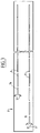
- Figure 1 shows an apparatus 1 according to the invention.
- This comprises a first conveyor belt 2 for supplying metal cans in two rows.
- the cans in the first row are designated with 3; those in the second row with 4.
- the cans are closed at the bottom and open at the top and are cylindrical in this embodiment.
- the first conveyor belt 2 is driven at a predetermined speed using drive means (not drawn).
- the apparatus 1 to be described hereinbelow transfers the cans 3, 4 from the first conveyor belt 2 to a second conveyor belt 5 extending in transverse direction thereof which is moved by drive means (not drawn) considerably more slowly than the first conveyor belt 2 and has a correspondingly greater width for this speed.
- This conveyor belt 5 can for instance be a steel conveyor mat for carrying lacquered, still wet cans through a drying oven.
- the rows of cans 3, 4 are picked up simultaneously from the first conveyor belt 2 in groups of for example nine cans by means of a suction beam 6.
- this suction beam 6 comprises a sole 7 which is selectively connectable to a suction pump 10 via two rows of slotted holes 8, 9 respectively.
- the sole 7 In the position shown in figure 1 the sole 7 is situated above two groups of cans 3, 4 for picking up.
- the distance of the sole 7 from the upper rim of these cans 3, 4 is small such that when the slotted holes 8, 9 are brought into communication with the suction pump 10 in the manner to be described hereinafter the relevant cans 3, 4 are drawn by underpressure against the sole.
- the suction beam 6, which is supported by drive means to be described hereinafter, transports the picked up groups of cans 3, 4 via a specific path to the second conveyor belt 5 where the connection between the slotted holes 8, 9 and the suction pump 10 is broken and the cans thus deposited onto the second conveyor belt.
- the suction beam 6 is only movable in a horizontal plane.
- the conveyor belts 2 and 5 lie with their active upper parts in a common horizontal plane.
- the suction beam 6 is supported via two pivots 11. These pivots each form part of a drive device, which two drive devices are identical.
- the drive devices (which will be described below) always displace the suction beam parallel to itself over the longitudinal distance in the direction of the conveyor belt 2 between the pivots 11.
- the whole apparatus is driven by a motor 12.
- This drives a gear wheel 13 via a transmission.
- a wheel 14 Via a geared belt 15 this wheel 14 drives a flywheel 16 in addition to the wheel 14' forming part of the second drive device.
- This second drive device is identical to the first. Therefore only the first drive device will be discussed.
- the driven wheel 14 carries on its periphery a pivot 17.
- a straight rod 18 and two rods 19, 20 forming a mutual angle the pivot 17 is connected to the pivot 11 which is one of the two pivots supporting the suction beam 6.
- a pivot 21 Situated at the transition between the rods 19 and 20 is a pivot 21 to which is connected a rod 22, whereof the end remote from the pivot 21 is pivotable round a fixed pivot 23.
- a correct choice of the speed of the first conveyor belt 2 and the drive speed of the wheel 14 can result in the speed of the suction beam 6 being substantially equal to the speed of the first conveyor belt 2 and having the same direction at the moment the cans 3, 4 are picked up.
- the speed of the suction beam 6 is practically zero, that is, substantially equal to the speed of the relatively very slow moving conveyor belt 5. This is the tiplike zone of the path 24 shown in figure 2 in which the speed of the suction beam 6 is reduced to zero and reverses direction.
- the position of the pivot 11 is designated respectively with A1, A2, A3, A4.
- the position of the pivot 21 is designated correspondingly with respectively B1, B2, B3, B4.
- the position of the pivot 17 is designated respectively with C1, C2, C3, C4.
- suction beam 6 is coupled to the suction pump 10 at the correct moment for suction of the cans 3, 4 and again decoupled for depositing the cans 3, 4.
- two wheels 26, 26' are connected to wheel 14' which drive a piston rod 28 reciprocally via an eccentric pin 27.
- the suction pump 10 driven by a motor 32 is connected to a suction conduit 30 which branches to two identical controllable valve systems, only one of which will be discussed.
- a cylinder 31, in which the piston 29 is reciprocally movable, is connected to the suction conduit 31 and connects to a flexible, second suction conduit 33 which is connected to the suction beam 6 and communicates with the slotted holes 8, 9.
- the piston 29 is movable in the manner described between two positions. In the one position the connection between the suction conduits 30 and 33 is blocked and no suction of products takes place, while in the other position the suction conduit 30 communicates with suction conduit 33 and products can be gripped by suction.
- the switch point suction ON - suction OFF is adjustable; the disc 26 is lockable in a desired angular position relative to the shaft to which it is fixed.
- the block 50 can be locked in a desired position on the rod 28. With these two adjustments suction ON - suction OFF can be selected individually.
- the said fixed positions in particular those of the drive motor 12, the wheels 14, 14' and the pivots 23, 23', are related to a frame 34, by means of which the apparatus 1 occupies a fixed position.
- Figure 3 shows that the rows of slotted holes 8, 9 are preferably staggered at their infeed side. Thus prevented is that products picked up from the row located to the outside can knock over products from the row located to the inside. At the ends the last slotted holes 35, 36 have curved slotted holes 37 which have the same radius of curvature as the cans 3, 4. A high level of pick-up reliability is hereby ensured.
Abstract
The invention provides an apparatus (1) for supplying in at least one substantially continuous row onto a first conveyor belt (2) products, particularly beaker-shaped articles open at the top such as metal cans (3, 4), whereof at least the outer surface of the body is provided with a still wet lacquer layer, and transferring these products onto a second conveyor belt (5) extending transversely of the first conveyor belt, which apparatus comprises pick-up means for picking up products in successive groups from the first conveyor belt, displacing said products parallel to themselves and depositing these groups of products in rows extending transversely of the direction of the second conveyor belt, which pick-up means are equipped for gripping the products from the top, wherein the speed of the pick-up means relative to the first and second conveyor belts is substantially zero during respectively picking up and depositing of the products.
Description
- To transfer products from a conveyor belt to a second conveyor belt lying transversely thereof use is usually made of pusher members. Such pusher members can transfer the products or groups of products in sideways direction from the first conveyor belt onto the second conveyor belt. A problem arises however if these products may not be touched on their sides. This is for instance the case in the situation where the products are lacquered metal cans which have to be placed in an oven for the purpose of drying the lacquer therein.
- The invention provides for this purpose an apparatus for supplying in at least one substantially continuous row onto a first conveyor belt products, particularly beaker-shaped articles open at the top such as metal cans, whereof at least the outer surface of the body is provided with a still wet lacquer layer, and transferring these products onto a second conveyor belt extending transversely of the first conveyor belt, which apparatus comprises pick-up means for picking up products in successive groups from the first conveyor belt, displacing said products parallel to themselves and depositing these groups of products in rows extending transversely of the direction of the second conveyor belt, which pick-up means are equipped for gripping the products from the top, wherein the speed of the pick-up means relative to the first and second conveyor belts is substantially zero during respectively picking up and depositing of the products.
- In particular this apparatus can be embodied such that the pick-up means comprise selectively energizable lifting means for lifting product from the first conveyor belt and depositing said products onto the second conveyor belt.
- The lifting means can be of electromagnetic type for handling products which consist at least partly of ferromagnetic material. Aluminium cans however cannot be handled with such an apparatus. In order to make an apparatus universally applicable the embodiment is therefore recommended in which the pick-up means comprise a sole with at least one opening connected to a source of underpressure for picking up the products by suction, which source of underpressure can be controlled for picking up the products by suction in the region of the first conveyor belt, maintaining this suction during transfer of these products and terminating this suction in the region of the second conveyor belt.
- It will be apparent that a sole grips only on the upper rim of the products, in particular metal cans, which is not lacquered and not sensitive to contact.
- In preference the apparatus is embodied such that the pick-up means are driven by drive means in a generally droplet-shaped path having a portion with maximal displacement speed substantially parallel to the first conveyor belt for picking up products therefrom, and a portion where the speed reverses direction substantially parallel to the second conveyor belt for depositing products thereon. With such an embodiment is achieved that pick-up of the products from the first conveyor belt and depositing thereof on the second conveyor belt takes place very fluently and without disturbance.
- A great simplicity is achieved in the mechanical construction of the apparatus with an embodiment in which the active parts of the first and second conveyor belt lie in the same horizontal plane and the pick-up means are only displaceable in a plane parallel thereto at a small height above the products.
- In the above described embodiment in which the pick-up means comprise a sole with a suction opening the apparatus can with advantage have the special feature that the opening is embodied as a row of holes.
- A great reliability in picking up the products is ensured with an embodiment in which the opening has on its side facing the feed side of the products a shape corresponding with the shape of the downstream side of the upper part of the products. This embodiment has the great advantage of either gripping or not gripping the last product in the group with a great change accuracy, wherein the uncertainty interval is reduced to negligible proportions.
- Particularly for handling cylindrical cans this variant may have the feature that the opening comprises at least one straight slotted hole which co-acts with a slotted hole having substantially the same radius of curvature as the cans.
- A specific embodiment has the feature that the first conveyor belt supplies the products in two rows and that the pick-up means are equipped for simultaneously picking up two groups, wherein these groups are mutually staggered on the feed side such that picked up products from the row remote from the second conveyor belt cannot come into contact with products in the other row.
- It will be apparent that the above described droplet-shaped path with specific speeds at the location of the two conveyor belts must in preference be realized with the simplest means. The apparatus must nevertheless operate wholly reliably and disturbance-free in all conditions. In this respect a preferred embodiment of the invention can have the feature that the drive means comprise at least two identical drive devices engaging on the pick-up means at a mutual distance in the lengthwise direction of the first conveyor belt and driven at equal phase by the motor means, each of which drive devices comprises:
a wheel driven rotatably round a fixed vertical axis;
a first arm connected pivotally thereto which pivotally supports the pick-up means; and
a second arm pivotally connected to this first arm and pivotable at its free end round a fixed axis. - A very simple embodiment with an automatic synchronization between the energizing of the pick-up means and the phase of a cycle is obtained with an embodiment in which a valve is arranged between the source of underpressure and the pick-up means, the drive means comprise one motor and this motor also serves to control the valve synchronously with the pick-up means between an open position in which the products can be gripped by suction and a closed position.
- Since the pick-up means are subject to great accelerations when following the droplet-shaped path a proportionally large motor power is necessary for the driving. The motor must be designed for the greatest accelerations. According to the invention however a considerably smaller motor power can suffice using an embodiment in which the drive means comprise flywheel means.
- The invention will now be elucidated with reference to the annexed drawing, in which:
- figure 1 shows a partly broken away perspective view of an apparatus according to the invention;
- figure 2 shows a schematic top view of one drive device for the pick-up means in a number of phases of a cycle; and
- figure 3 shows a bottom view of a suction sole.
- Figure 1 shows an apparatus 1 according to the invention. This comprises a
first conveyor belt 2 for supplying metal cans in two rows. The cans in the first row are designated with 3; those in the second row with 4. The cans are closed at the bottom and open at the top and are cylindrical in this embodiment. Thefirst conveyor belt 2 is driven at a predetermined speed using drive means (not drawn). - The apparatus 1 to be described hereinbelow transfers the cans 3, 4 from the
first conveyor belt 2 to asecond conveyor belt 5 extending in transverse direction thereof which is moved by drive means (not drawn) considerably more slowly than thefirst conveyor belt 2 and has a correspondingly greater width for this speed. Thisconveyor belt 5 can for instance be a steel conveyor mat for carrying lacquered, still wet cans through a drying oven. - The rows of cans 3, 4 are picked up simultaneously from the
first conveyor belt 2 in groups of for example nine cans by means of asuction beam 6. As shown in figure 3, thissuction beam 6 comprises a sole 7 which is selectively connectable to asuction pump 10 via two rows of slottedholes holes suction pump 10 in the manner to be described hereinafter the relevant cans 3, 4 are drawn by underpressure against the sole. Thesuction beam 6, which is supported by drive means to be described hereinafter, transports the picked up groups of cans 3, 4 via a specific path to thesecond conveyor belt 5 where the connection between the slottedholes suction pump 10 is broken and the cans thus deposited onto the second conveyor belt. - The
suction beam 6 is only movable in a horizontal plane. Theconveyor belts - The
suction beam 6 is supported via twopivots 11. These pivots each form part of a drive device, which two drive devices are identical. The drive devices (which will be described below) always displace the suction beam parallel to itself over the longitudinal distance in the direction of theconveyor belt 2 between thepivots 11. - For a good understanding of the operation of each of both drive devices reference is now made to figure 2.
- The whole apparatus 1, with the exception of the
suction pump 10, is driven by amotor 12. This drives agear wheel 13 via a transmission. Rigidly coupled to thiswheel 13 is awheel 14. Via a gearedbelt 15 thiswheel 14 drives aflywheel 16 in addition to the wheel 14' forming part of the second drive device. Use is made for driving the flywheel of a pneumatic coupling. A gradual start can be achieved herewith, and protection in the case of an emergency stop. This second drive device is identical to the first. Therefore only the first drive device will be discussed. - The driven
wheel 14 carries on its periphery apivot 17. By means of astraight rod 18 and tworods 19, 20 forming a mutual angle thepivot 17 is connected to thepivot 11 which is one of the two pivots supporting thesuction beam 6. Situated at the transition between therods 19 and 20 is apivot 21 to which is connected arod 22, whereof the end remote from thepivot 21 is pivotable round a fixedpivot 23. With this rod construction is achieved that the path of thepivot 11, and therewith also the path of thesuction beam 6, has the form designated with 24. A correct choice of the speed of thefirst conveyor belt 2 and the drive speed of thewheel 14 can result in the speed of thesuction beam 6 being substantially equal to the speed of thefirst conveyor belt 2 and having the same direction at the moment the cans 3, 4 are picked up. Achieved in the same manner is that, when the cans 25 (which in the embodiment according to figure 2 are supplied in only one row) are deposited onto thesecond conveyor belt 5, the speed of thesuction beam 6 is practically zero, that is, substantially equal to the speed of the relatively very slow movingconveyor belt 5. This is the tiplike zone of thepath 24 shown in figure 2 in which the speed of thesuction beam 6 is reduced to zero and reverses direction. - For the sake of the clarity of the operation of the drive device this is shown in different phases of a cycle. The position of the
pivot 11 is designated respectively with A¹, A², A³, A⁴. The position of thepivot 21 is designated correspondingly with respectively B¹, B², B³, B⁴. The position of thepivot 17 is designated respectively with C¹, C², C³, C⁴. - It is essential that the
suction beam 6 is coupled to thesuction pump 10 at the correct moment for suction of the cans 3, 4 and again decoupled for depositing the cans 3, 4. For this purpose twowheels 26, 26' are connected to wheel 14' which drive a piston rod 28 reciprocally via an eccentric pin 27. Thesuction pump 10 driven by amotor 32 is connected to asuction conduit 30 which branches to two identical controllable valve systems, only one of which will be discussed. A cylinder 31, in which thepiston 29 is reciprocally movable, is connected to the suction conduit 31 and connects to a flexible,second suction conduit 33 which is connected to thesuction beam 6 and communicates with the slottedholes piston 29 is movable in the manner described between two positions. In the one position the connection between thesuction conduits suction conduit 30 communicates withsuction conduit 33 and products can be gripped by suction. - The switch point suction ON - suction OFF is adjustable; the
disc 26 is lockable in a desired angular position relative to the shaft to which it is fixed. The block 50 can be locked in a desired position on the rod 28. With these two adjustments suction ON - suction OFF can be selected individually. - As a result of the positive coupling between the action of the said drive devices and the corresponding control of the suctions an automatically operating synchronization takes place which cannot be disturbed by ageing.
- The said fixed positions, in particular those of the
drive motor 12, thewheels 14, 14' and thepivots 23, 23', are related to aframe 34, by means of which the apparatus 1 occupies a fixed position. - Figure 3 shows that the rows of slotted
holes holes holes 37 which have the same radius of curvature as the cans 3, 4. A high level of pick-up reliability is hereby ensured.
Claims (12)
- Apparatus for supplying in at least one substantially continuous row onto a first conveyor belt products, particularly beaker-shaped articles open at the top such as metal cans, whereof at least the outer surface of the body is provided with a still wet lacquer layer, and transferring these products onto a second conveyor belt extending transversely of the first conveyor belt, which apparatus comprises pick-up means for picking up products in successive groups from the first conveyor belt, moving said products parallel to themselves and depositing these groups of products in rows extending transversely of the direction of the second conveyor belt, which pick-up means are equipped for gripping the products from the top, wherein the speed of the pick-up means relative to the first and second conveyor belts is substantially zero during respectively picking up and depositing of the products.
- Apparatus as claimed in claim 1, characterized in that the pick-up means comprise selectively energizable lifting means for lifting products from the first conveyor belt and depositing said products onto the second conveyor belt.
- Apparatus as claimed in claim 2, characterized in that the pick-up means comprise a sole with at least one opening connected to a source of underpressure for picking up the product by suction, which source of underpressure can be controlled for picking up the products by suction in the region of the first conveyor belt, maintaining this suction during transfer of these products and terminating this suction in the region of the second conveyor belt.
- Apparatus as claimed in claim 1, characterized in that the pick-up means are driven by drive means in a generally droplet-shaped path having a portion with maximal displacement speed substantially parallel to the first conveyor belt for picking up products therefrom, and a portion where the speed reverses direction substantially parallel to the second conveyor belt for depositing products thereon.
- Apparatus as claimed in claim 2, characterized in that the active parts of the first and second conveyor belt lie in the same horizontal plane and the pick-up means are only displaceable in a plane parallel thereto at a small height above the products.
- Apparatus as claimed in claim 3, characterized in that the opening is embodied as a row of holes.
- Apparatus as claimed in claim 3, characterized in that the opening has on its side facing the feed side of the products a shape corresponding with the shape of the downstream side of the upper part of the products.
- Apparatus as claimed in claim 7 for handling cylindrical cans, characterized in that the opening comprises at least one straight slotted hole which co-acts with a slotted hole having substantially the same radius of curvature as the cans.
- Apparatus as claimed in claim 4, characterized in that the first conveyor belt supplies the products in two rows and that the pick-up means are equipped for simultaneously picking up two groups, wherein these groups are mutually staggered on the feed side such that picked up products from the row remote from the second conveyor belt cannot come into contact with products in the other row.
- Apparatus as claimed in claim 4, characterized in that the drive means comprise at least two identical drive devices engaging on the pick-up means at a mutual distance in the lengthwise direction of the first conveyor belt and driven at equal phase by the motor means, each of which drive devices comprises:
a wheel driven rotatably round a fixed vertical axis;
a first arm connected pivotally thereto which pivotally supports the pick-up means; and
a second arm pivotally connected to this first arm and pivotable at its free end round a fixed axis. - Apparatus as claimed in claims 3 and 10, characterized in that a valve is arranged between the source of underpressure and the pick-up means, that the drive means comprise one motor and that this motor also serves to control the valve synchronously with the pick-up means between an open position in which the products can be picked up by suction and a closed position.
- Apparatus as claimed in claim 4, characterized in that the drive means comprise flywheel means.
Priority Applications (6)
| Application Number | Priority Date | Filing Date | Title |
|---|---|---|---|
| EP92200965A EP0563461A1 (en) | 1992-04-03 | 1992-04-03 | Loading apparatus |
| US07/946,860 US5311978A (en) | 1992-04-03 | 1992-09-17 | Loading apparatus |
| TW082102238A TW210987B (en) | 1992-04-03 | 1993-03-25 | Loading apparatus |
| ZA932361A ZA932361B (en) | 1992-04-03 | 1993-04-01 | Loading apparatus |
| JP5076780A JPH06219551A (en) | 1992-04-03 | 1993-04-02 | Loading device |
| KR1019930005639A KR930021517A (en) | 1992-04-03 | 1993-04-03 | Adsorption Transfer Device of Goods |
Applications Claiming Priority (1)
| Application Number | Priority Date | Filing Date | Title |
|---|---|---|---|
| EP92200965A EP0563461A1 (en) | 1992-04-03 | 1992-04-03 | Loading apparatus |
Publications (1)
| Publication Number | Publication Date |
|---|---|
| EP0563461A1 true EP0563461A1 (en) | 1993-10-06 |
Family
ID=8210530
Family Applications (1)
| Application Number | Title | Priority Date | Filing Date |
|---|---|---|---|
| EP92200965A Withdrawn EP0563461A1 (en) | 1992-04-03 | 1992-04-03 | Loading apparatus |
Country Status (6)
| Country | Link |
|---|---|
| US (1) | US5311978A (en) |
| EP (1) | EP0563461A1 (en) |
| JP (1) | JPH06219551A (en) |
| KR (1) | KR930021517A (en) |
| TW (1) | TW210987B (en) |
| ZA (1) | ZA932361B (en) |
Cited By (6)
| Publication number | Priority date | Publication date | Assignee | Title |
|---|---|---|---|---|
| DE4445108A1 (en) * | 1994-12-19 | 1996-06-20 | Ltg Lufttechnische Gmbh | Transfer device for goods, in particular cans |
| DE19623872A1 (en) * | 1996-06-14 | 1997-12-18 | Ltg Lufttechnische Gmbh | Method for transferring groups of aluminium cans containing different types of drink |
| DE19624709A1 (en) * | 1996-06-21 | 1998-01-15 | Ltg Lufttechnische Gmbh | Vacuum-operated transfer unit for drinks cans from one conveyor to another |
| EP1164099A1 (en) * | 2000-06-16 | 2001-12-19 | MARCHESINI GROUP S.p.A. | Method and device for transferring blister packs and the like between two conveyor lines |
| EP1260469A1 (en) * | 2001-05-18 | 2002-11-27 | AUTEFA automation GmbH | Transferring apparatus for bottle treatment plants |
| DE10127896A1 (en) * | 2001-06-08 | 2002-12-19 | Indag Gmbh | Method for transferring drinks sachets arriving in columns on conveyor into single row on second conveyor at right angles to first uses carrier bar for sachets which forms part of parallelogram of levers |
Citations (8)
| Publication number | Priority date | Publication date | Assignee | Title |
|---|---|---|---|---|
| US2071859A (en) * | 1936-03-16 | 1937-02-23 | Leo E Steiner | Magnetic transfer device |
| DE805995C (en) * | 1945-06-08 | 1951-06-11 | Turners Asbestos Cement Compan | Device for producing a stack of plates or the like. |
| US2619237A (en) * | 1948-06-30 | 1952-11-25 | American Can Co | Machine for feeding, transferring, and compacting articles into a unit layer |
| US3033604A (en) * | 1959-02-18 | 1962-05-08 | Winkler Sallert & Co Ag Maschf | Lifting and transporting device for holding hollow articles |
| US3072252A (en) * | 1959-03-17 | 1963-01-08 | Continental Can Co | Glass jar unloader |
| US3776342A (en) * | 1972-01-27 | 1973-12-04 | Emhart Corp | Apparatus for transferring articles between moving conveyors |
| GB1434858A (en) * | 1973-04-03 | 1976-05-05 | Heye Hermann | Apparatus for simultaneously transferring a plurality of objects between two conveyors |
| US5044488A (en) * | 1989-12-08 | 1991-09-03 | Liberty Glass Company | Article transfer apparatus |
Family Cites Families (6)
| Publication number | Priority date | Publication date | Assignee | Title |
|---|---|---|---|---|
| US3360102A (en) * | 1964-06-17 | 1967-12-26 | Shenango Ceramics Inc | Kiln loader and unloader |
| US3601243A (en) * | 1969-05-29 | 1971-08-24 | Interpace Corp | Transfer mechanism |
| US3805943A (en) * | 1971-03-24 | 1974-04-23 | W Warren | Swivel-lift vacuum article loader |
| US4039073A (en) * | 1976-04-07 | 1977-08-02 | Ohlhaver Homer W | Push-on device |
| US4081073A (en) * | 1976-06-01 | 1978-03-28 | Powers Manufacturing, Inc. | Apparatus for transferring parts |
| DE2733823A1 (en) * | 1977-07-27 | 1979-02-15 | Nsm Magnettechnik | Mechanical handling system for small parts - has intermediate storage conveyors subject to speed and time controls according to feedback from counters |
-
1992
- 1992-04-03 EP EP92200965A patent/EP0563461A1/en not_active Withdrawn
- 1992-09-17 US US07/946,860 patent/US5311978A/en not_active Expired - Fee Related
-
1993
- 1993-03-25 TW TW082102238A patent/TW210987B/en active
- 1993-04-01 ZA ZA932361A patent/ZA932361B/en unknown
- 1993-04-02 JP JP5076780A patent/JPH06219551A/en active Pending
- 1993-04-03 KR KR1019930005639A patent/KR930021517A/en not_active IP Right Cessation
Patent Citations (8)
| Publication number | Priority date | Publication date | Assignee | Title |
|---|---|---|---|---|
| US2071859A (en) * | 1936-03-16 | 1937-02-23 | Leo E Steiner | Magnetic transfer device |
| DE805995C (en) * | 1945-06-08 | 1951-06-11 | Turners Asbestos Cement Compan | Device for producing a stack of plates or the like. |
| US2619237A (en) * | 1948-06-30 | 1952-11-25 | American Can Co | Machine for feeding, transferring, and compacting articles into a unit layer |
| US3033604A (en) * | 1959-02-18 | 1962-05-08 | Winkler Sallert & Co Ag Maschf | Lifting and transporting device for holding hollow articles |
| US3072252A (en) * | 1959-03-17 | 1963-01-08 | Continental Can Co | Glass jar unloader |
| US3776342A (en) * | 1972-01-27 | 1973-12-04 | Emhart Corp | Apparatus for transferring articles between moving conveyors |
| GB1434858A (en) * | 1973-04-03 | 1976-05-05 | Heye Hermann | Apparatus for simultaneously transferring a plurality of objects between two conveyors |
| US5044488A (en) * | 1989-12-08 | 1991-09-03 | Liberty Glass Company | Article transfer apparatus |
Cited By (15)
| Publication number | Priority date | Publication date | Assignee | Title |
|---|---|---|---|---|
| DE4445108A1 (en) * | 1994-12-19 | 1996-06-20 | Ltg Lufttechnische Gmbh | Transfer device for goods, in particular cans |
| EP0718223A1 (en) * | 1994-12-19 | 1996-06-26 | Ltg Lufttechnische Gmbh | Transfer device for goods, especially for cans |
| US5579893A (en) * | 1994-12-19 | 1996-12-03 | Ltg Lufttechnische Gmbh | Transfer device for products, in particular cans |
| US5799770A (en) * | 1996-06-14 | 1998-09-01 | LTG Lufttechnische Gesellschaft mit beschrankter | Method for the transfer of separated goods and transfer device |
| DE19623872C2 (en) * | 1996-06-14 | 1998-04-16 | Ltg Lufttechnische Gmbh | Process for the transfer of separated goods and transfer device |
| DE19623872A1 (en) * | 1996-06-14 | 1997-12-18 | Ltg Lufttechnische Gmbh | Method for transferring groups of aluminium cans containing different types of drink |
| DE19624709A1 (en) * | 1996-06-21 | 1998-01-15 | Ltg Lufttechnische Gmbh | Vacuum-operated transfer unit for drinks cans from one conveyor to another |
| US6223883B1 (en) | 1996-06-21 | 2001-05-01 | Ltg Lufttechnische Gesellschaft Mit Beschrankter Haftung | Vacuum control for a transfer device, in particular for cans |
| DE19624709C2 (en) * | 1996-06-21 | 2002-09-19 | Ltg Lufttechnische Gmbh | Vacuum control in a transfer device, especially for cans |
| EP1164099A1 (en) * | 2000-06-16 | 2001-12-19 | MARCHESINI GROUP S.p.A. | Method and device for transferring blister packs and the like between two conveyor lines |
| US6948608B2 (en) | 2000-06-16 | 2005-09-27 | Marchesini Group Spa | Method and a device for transferring blister packs and the like to the feeding line of a packaging machine |
| EP1260469A1 (en) * | 2001-05-18 | 2002-11-27 | AUTEFA automation GmbH | Transferring apparatus for bottle treatment plants |
| DE10127896A1 (en) * | 2001-06-08 | 2002-12-19 | Indag Gmbh | Method for transferring drinks sachets arriving in columns on conveyor into single row on second conveyor at right angles to first uses carrier bar for sachets which forms part of parallelogram of levers |
| US6726001B2 (en) | 2001-06-08 | 2004-04-27 | Indag Gesellschaft Fuer Industriebedarf Mbh & Co. Betriebs Kg | Transfer apparatus and method for film bags |
| DE10127896B4 (en) * | 2001-06-08 | 2005-02-24 | Indag Gesellschaft für Industriebedarf mbH & Co. Betriebs KG | Transfer device and method for foil bags |
Also Published As
| Publication number | Publication date |
|---|---|
| KR930021517A (en) | 1993-11-22 |
| JPH06219551A (en) | 1994-08-09 |
| US5311978A (en) | 1994-05-17 |
| ZA932361B (en) | 1993-09-13 |
| TW210987B (en) | 1993-08-11 |
Similar Documents
| Publication | Publication Date | Title |
|---|---|---|
| US4976584A (en) | Apparatus for loading cartons onto pallets | |
| US5921375A (en) | Transfer device and assembly of transfer devices | |
| DK2961674T3 (en) | Transport device for loading or unloading of freight goods which can be comminuted | |
| EP0329870B1 (en) | A device for transferring a lithographic plate | |
| US6748725B2 (en) | Continuous circular motion case packing and depacking apparatus and method | |
| US6726001B2 (en) | Transfer apparatus and method for film bags | |
| US4846625A (en) | Device for transferring objects, particularly glass panes | |
| US6220424B1 (en) | Method and apparatus for transferring items from a conveyor | |
| CN113291774B (en) | Loading and unloading integrated machine and automatic loading and unloading system of container | |
| EP0563461A1 (en) | Loading apparatus | |
| US4599025A (en) | Stacker assembly | |
| EP0610780B1 (en) | Article palletizer/depalletizer | |
| NL1006715C2 (en) | Product transfer device as well as an assembly comprising such a product transfer device. | |
| JP3855108B2 (en) | Rectangular article loading and unloading equipment | |
| CN113135033A (en) | Apparatus for singulating printing plates | |
| EP4116241A1 (en) | Compact depalletizing machine | |
| EP0755882B1 (en) | Apparatus for loading and/or unloading a container with stacks of packages, such as for instance egg trays | |
| KR100666802B1 (en) | A packaging machine | |
| US5303531A (en) | Packaging machine | |
| CN110494379B (en) | Unstacking device for unstacking transport containers from a loading surface and method for operating the unstacking device | |
| CN115921335A (en) | Sorting system | |
| EP1068140A1 (en) | Conveyors for feeding containers in equally spaced manner | |
| GB933094A (en) | Pan stacking and unstacking system | |
| EP0982250A1 (en) | Device for displacing through a certain height objects supplied in a row. | |
| JPH08198437A (en) | Article feeder |
Legal Events
| Date | Code | Title | Description |
|---|---|---|---|
| PUAI | Public reference made under article 153(3) epc to a published international application that has entered the european phase |
Free format text: ORIGINAL CODE: 0009012 |
|
| AK | Designated contracting states |
Kind code of ref document: A1 Designated state(s): AT BE CH DE DK ES FR GB GR IT LI LU MC NL PT SE |
|
| 17P | Request for examination filed |
Effective date: 19931104 |
|
| 17Q | First examination report despatched |
Effective date: 19941018 |
|
| GRAH | Despatch of communication of intention to grant a patent |
Free format text: ORIGINAL CODE: EPIDOS IGRA |
|
| STAA | Information on the status of an ep patent application or granted ep patent |
Free format text: STATUS: THE APPLICATION IS DEEMED TO BE WITHDRAWN |
|
| 18D | Application deemed to be withdrawn |
Effective date: 19960329 |