EP0563216B1 - Stackable bedding foundation - Google Patents
Stackable bedding foundation Download PDFInfo
- Publication number
- EP0563216B1 EP0563216B1 EP92902147A EP92902147A EP0563216B1 EP 0563216 B1 EP0563216 B1 EP 0563216B1 EP 92902147 A EP92902147 A EP 92902147A EP 92902147 A EP92902147 A EP 92902147A EP 0563216 B1 EP0563216 B1 EP 0563216B1
- Authority
- EP
- European Patent Office
- Prior art keywords
- assembly
- wires
- valleys
- peaks
- flattened
- Prior art date
- Legal status (The legal status is an assumption and is not a legal conclusion. Google has not performed a legal analysis and makes no representation as to the accuracy of the status listed.)
- Expired - Lifetime
Links
- 230000000712 assembly Effects 0.000 claims abstract description 23
- 238000000429 assembly Methods 0.000 claims abstract description 23
- 239000006260 foam Substances 0.000 claims description 3
- 239000004744 fabric Substances 0.000 claims description 2
- 238000010276 construction Methods 0.000 claims 1
- 229910000831 Steel Inorganic materials 0.000 description 5
- 239000010959 steel Substances 0.000 description 5
- 239000002184 metal Substances 0.000 description 3
- 238000004519 manufacturing process Methods 0.000 description 1
- 239000000463 material Substances 0.000 description 1
- 230000003019 stabilising effect Effects 0.000 description 1
Images


Classifications
-
- A—HUMAN NECESSITIES
- A47—FURNITURE; DOMESTIC ARTICLES OR APPLIANCES; COFFEE MILLS; SPICE MILLS; SUCTION CLEANERS IN GENERAL
- A47C—CHAIRS; SOFAS; BEDS
- A47C23/00—Spring mattresses with rigid frame or forming part of the bedstead, e.g. box springs; Divan bases; Slatted bed bases
- A47C23/005—Spring mattresses with rigid frame or forming part of the bedstead, e.g. box springs; Divan bases; Slatted bed bases foldable or dismountable
-
- A—HUMAN NECESSITIES
- A47—FURNITURE; DOMESTIC ARTICLES OR APPLIANCES; COFFEE MILLS; SPICE MILLS; SUCTION CLEANERS IN GENERAL
- A47C—CHAIRS; SOFAS; BEDS
- A47C23/00—Spring mattresses with rigid frame or forming part of the bedstead, e.g. box springs; Divan bases; Slatted bed bases
Definitions
- This invention relates generally to bedding, and more particularly to a nestably stackable bedding foundation.
- Bedding foundations or so-called box spring assemblies generally comprise spaced border wires between which are disposed coil or bent wire spring modules. As thus manufactured, these box spring assemblies are bulky and shipping to the manufacturer for application of padding and covering thereto is costly because of space requirements. In order to reduce the space requirements, it is customary to compress the assemblies to reduce their individual thicknesses and, when compressed, to tie them in their compressed state. This involves providing presses and ties which are expensive, and the extra operations of pressing and tieing the assemblies. At the delivery end, the manufacturer must cut and discard the ties before applying the covering. These additional material and handling costs increase the end cost of box spring assemblies.
- United States Specification No. 4,377,279 discloses a foundation unit which can be temporarily collapsed for storage and shipping.
- a plurality of flat support members are hingedly secured along opposite sides to top and bottom planar structures.
- Stabilising means are provided to maintain the support members upright, or to allow the unit to collapse.
- Another object of the present invention has been to provide a bedding foundation assembly which is relatively simple to manufacture, and which may substitute for a traditional box spring assembly having coil spring modules.
- the present invention is directed at a nestably stackable bedding foundation assembly for use in place of the traditional box spring assembly.
- This bedding foundation assembly comprises a rectangular border wire, a plurality of transversely spaced, parallel and longitudinally extending support wires, and a plurality of longitudinally spaced, parallel and transversely extending upper connector wires, the support wires and the upper connector wires having ends connected to the border wire.
- the support wires are formed so as to be generally corrugated along their lengths, the corrugatedly formed support wires having peaks and valleys, the peaks being generally coplanar with a plane defined by the border wire, the valleys being vertically displaced beneath and intermediate of the peaks, the upper connector wires being fixedly connected intermediate of their ends along their lengths to the peaks of the support wires such that the assembly is nestably stackable.
- the longitudinal voids between the peaks of the support wires are preferably of a greater dimension than the valleys of the support wires.
- This configuration enables one nestably stackable bedding foundation assembly to be nestedly stacked atop a second assembly since the support wire valleys of the first assembly may enter into the voids between the peaks of the support wires of the second assembly.
- Such a nestedly stacked arrangement results in a total height dimension which is less than the sum of the individual assembly height dimensions.
- the primary advantage of the present invention is that it enables relatively inexpensive bedding foundation wire cores to be tightly compacted and shipped in a minimum of space to an assembly destination, thereby reducing the ultimate cost of the core to the assembler.
- bedding foundation assemblies may be rapidly loaded by a manufacturer for transportation to the destination of assembly without the need for compressing and tieing the assemblies.
- Yet another advantage of the present invention is that the need for costly presses and ties necessary to compress a conventional box spring assembly for transportation is obviated.
- a further advantage of the present invention is that bedding foundation assemblies may be rapidly unloaded without the time consuming and labor intensive tasks of clipping and discarding the tie wires used to hold conventional box spring assemblies in a compressed state.
- a bedding foundation 1 is illustrated.
- the foundation 1 has a rectangular wooden base frame 2 on which are attached transverse wooden slats 3.
- Atop these transverse slats 3 is the nestably stackable assembly or wire core 4, which is the invention of this application.
- a foam pad 5 overlies the nestably stackable assembly 4, and a fabric covering 6 overlies the foam pad 5 and surrounds the nestably stackable assembly 4 and the base frame 2.
- a rectangular steel border wire 10 having two parallel sides 11, 11 and two parallel ends 12, 12, with the parallel sides 11, 11 being longer than the parallel ends 12, 12.
- Transversely-spaced, parallel, and longitudinally-extending steel support wires 13 are parallel to the border wire sides 11, 11 and have ends 14 which are crimped around the ends 12, 12 of the border wire 10.
- These support wires 13 are formed so as to be generally corrugatedly-shaped along their lengths, having peaks 15 and valleys 16. These peaks 15 and valleys 16 are flattened at their extrememost locations 17 and 18, respectively.
- These flattened peaks 17 are generally coplanar with the plane defined by the border wire 10, with the flattened valleys 18 being vertically spaced beneath and intermediate of the flattened peaks 17.
- upper connector wires 19 extend parallel to the border wire ends 12, 12 and have ends 20 which are crimped around the border wire sides 11, 11. These upper connector wires 19 are welded intermediate of their ends along their lengths 21 to the flattened peaks 17 of the support wires 13. The upper connector wires form a generally planar top of the assembly 4.
- the support wires 13 define a plurality of support wire means depending from and forming part of the upper connector wires, each support wire means of which tapers downwardly from the planar top to a lower end, the lower ends being located in a common base plane and being adapted to be secured to a foundation base 2.
- Longitudinally-spaced, parallel, and transversely-extending steel lower connector wires 22 extend parallel to the border wire ends 12, 12 and are welded at their ends 23 and intermediate of their ends along their lengths 24 to the flattened valleys 16 of the support wires 13.
- the support wires 13 have flattened peaks 17 and flattened valleys 18, with the support wire ends 14 being crimped around the border wire 10.
- three upper connector wires 19 per flattened peak 17 are illustrated, along with one lower connector wire 21 per flattened valley 18.
- the flattened valleys 18 of the support wires 13 are stapled or otherwise attached to the transverse slats 3 which are in turn affixed to the base frame 2.
- additional steel end wires 25 may be added either before or after the stackable assembly 4 has reached its final assembly destination. These end wires 25 have ends 26 and 27 which are crimped around the border wire 10 and the endmost upper connector wire 28, respectively. These end wires 25 provide additional stiffness to the stackable assembly 4 in an edgemost location of the ends of the assembly 4 so as to prevent the end border wires from deflecting and being permanently distorted when a person sits on the end of a bed of which the foundation forms a part.
- the metal core portion of a bedding foundation is generally manufactured by a supplier, who then ships it to an assembler.
- the assembler adds to the metal core a wooden base 2, slats 3, padding 5, and upholstery 6 to make a completed product.
- first stackable assembly or core 4 may be placed upon a surface with the flattened valleys 18 of the support wires 13 oriented downwardly and the flattened peaks 17 of the support wires 13 oriented upwardly.
- a second like assembly 4 is placed atop the first assembly 4, with its flattened support wire valleys 18 and flattened support wire peaks 17 likewise oriented downwardly and upwardly, respectively.
- the flattened valleys 18 of the second assembly 4 are thereby allowed to enter into the voids between the flattened peaks 17 of the first assembly 4.
- the second assembly 4 nestles downwardly within the first assembly 4 until the outside dimension of the valleys 16 of the second assembly 4 is equal to the inside dimension of the valleys 16 of the first assembly 4. At this point, the second assembly 4 comes to rest within the first assembly 4, with the overall heighth of the nested assemblies being substantially less than the sum of the individual heighths of the assemblies.
- any number of assemblies may be nested and stacked together for storage or shipment.
- FIG. 4 An alternative embodiment of the present invention is illustrated in Fig. 4.
- the optional end wires 25 have been removed and replaced with continuous longitudinal wires 31.
- These longitudinal wires 31 have their ends crimped around the border wire ends 12.
- These end wires 31 may be welded along their lengths to the upper connector wires 19 as desired.
- the lower connector wires 22 of the first embodiment of Figs. 1-3 have been eliminated. This facilitates stacking of the assemblies as illustrated in Fig. 6.
- the upper connector wires 19 are welded intermediate of their ends along their lengths to the underneath sides of the flattened peaks 17 of the support wires 13. This allows the longitudinal wires 31 to rest atop and be generally coplanar with the flattened peaks 17 of the support wires 13 when the assemblies are stacked as illustrated in Fig. 6.
Landscapes
- Mattresses And Other Support Structures For Chairs And Beds (AREA)
- Buffer Packaging (AREA)
- Combinations Of Kitchen Furniture (AREA)
- Wire Processing (AREA)
- Packaging Of Annular Or Rod-Shaped Articles, Wearing Apparel, Cassettes, Or The Like (AREA)
- Special Chairs (AREA)
- Stackable Containers (AREA)
Abstract
Description
- This invention relates generally to bedding, and more particularly to a nestably stackable bedding foundation.
- Bedding foundations or so-called box spring assemblies generally comprise spaced border wires between which are disposed coil or bent wire spring modules. As thus manufactured, these box spring assemblies are bulky and shipping to the manufacturer for application of padding and covering thereto is costly because of space requirements. In order to reduce the space requirements, it is customary to compress the assemblies to reduce their individual thicknesses and, when compressed, to tie them in their compressed state. This involves providing presses and ties which are expensive, and the extra operations of pressing and tieing the assemblies. At the delivery end, the manufacturer must cut and discard the ties before applying the covering. These additional material and handling costs increase the end cost of box spring assemblies.
- United States Specification No. 4,377,279 discloses a foundation unit which can be temporarily collapsed for storage and shipping. A plurality of flat support members are hingedly secured along opposite sides to top and bottom planar structures. Stabilising means are provided to maintain the support members upright, or to allow the unit to collapse.
- It has been one object of the invention of this application to construct a bedding foundation assembly that can be stacked for shipping without having to compress and tie the assembly.
- Another object of the present invention has been to provide a bedding foundation assembly which is relatively simple to manufacture, and which may substitute for a traditional box spring assembly having coil spring modules.
- The present invention is directed at a nestably stackable bedding foundation assembly for use in place of the traditional box spring assembly. This bedding foundation assembly comprises a rectangular border wire, a plurality of transversely spaced, parallel and longitudinally extending support wires, and a plurality of longitudinally spaced, parallel and transversely extending upper connector wires, the support wires and the upper connector wires having ends connected to the border wire. According to the invention, the support wires are formed so as to be generally corrugated along their lengths, the corrugatedly formed support wires having peaks and valleys, the peaks being generally coplanar with a plane defined by the border wire, the valleys being vertically displaced beneath and intermediate of the peaks, the upper connector wires being fixedly connected intermediate of their ends along their lengths to the peaks of the support wires such that the assembly is nestably stackable. The longitudinal voids between the peaks of the support wires are preferably of a greater dimension than the valleys of the support wires.
- This configuration enables one nestably stackable bedding foundation assembly to be nestedly stacked atop a second assembly since the support wire valleys of the first assembly may enter into the voids between the peaks of the support wires of the second assembly. Such a nestedly stacked arrangement results in a total height dimension which is less than the sum of the individual assembly height dimensions.
- The primary advantage of the present invention is that it enables relatively inexpensive bedding foundation wire cores to be tightly compacted and shipped in a minimum of space to an assembly destination, thereby reducing the ultimate cost of the core to the assembler.
- Another advantage of the present invention is that bedding foundation assemblies may be rapidly loaded by a manufacturer for transportation to the destination of assembly without the need for compressing and tieing the assemblies.
- Yet another advantage of the present invention is that the need for costly presses and ties necessary to compress a conventional box spring assembly for transportation is obviated.
- A further advantage of the present invention is that bedding foundation assemblies may be rapidly unloaded without the time consuming and labor intensive tasks of clipping and discarding the tie wires used to hold conventional box spring assemblies in a compressed state.
- The invention will now be described by way of example and with reference to the accompanying Drawings wherein:
- Fig. 1 is a perspective view, partially broken away, of a bedding foundation assembly embodying the invention of this application.
- Fig. 2 is a view taken along lines 2-2 of Fig. 1 illustrating the corrugatedly formed support wires and optional end connection wires.
- Fig. 3 is a view like Figure 2 but illustrating two unmounted foundations stacked and nested one within the other for shipment.
- Fig. 4 is a perspective view, partially broken away, of a bedding foundation assembly embodying an alternative embodiment of the present invention.
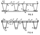
- Fig. 5 is a view taken along line 5-5 of Fig. 4.
- Fig. 6 is a view like Fig. 5 but illustrating the alternative embodiment foundations unmounted on base frames and stacked and nested one within the other for shipment.
- Referring first to Fig. 1, a
bedding foundation 1 is illustrated. Thefoundation 1 has a rectangularwooden base frame 2 on which are attached transversewooden slats 3. Atop thesetransverse slats 3 is the nestably stackable assembly or wire core 4, which is the invention of this application. A foam pad 5 overlies the nestably stackable assembly 4, and a fabric covering 6 overlies the foam pad 5 and surrounds the nestably stackable assembly 4 and thebase frame 2. - Describing the nestably stackable assembly 4 now in more detail, it comprises a rectangular
steel border wire 10 having twoparallel sides parallel ends parallel sides parallel ends steel support wires 13 are parallel to theborder wire sides ends 14 which are crimped around theends border wire 10. Thesesupport wires 13 are formed so as to be generally corrugatedly-shaped along their lengths, havingpeaks 15 andvalleys 16. Thesepeaks 15 andvalleys 16 are flattened at theirextrememost locations flattened peaks 17 are generally coplanar with the plane defined by theborder wire 10, with theflattened valleys 18 being vertically spaced beneath and intermediate of theflattened peaks 17. - Longitudinally-spaced, parallel, and transversely-extending steel
upper connector wires 19 extend parallel to theborder wire ends ends 20 which are crimped around theborder wire sides upper connector wires 19 are welded intermediate of their ends along theirlengths 21 to theflattened peaks 17 of thesupport wires 13. The upper connector wires form a generally planar top of the assembly 4. - The
support wires 13 define a plurality of support wire means depending from and forming part of the upper connector wires, each support wire means of which tapers downwardly from the planar top to a lower end, the lower ends being located in a common base plane and being adapted to be secured to afoundation base 2. - Longitudinally-spaced, parallel, and transversely-extending steel
lower connector wires 22 extend parallel to theborder wire ends ends 23 and intermediate of their ends along theirlengths 24 to theflattened valleys 16 of thesupport wires 13. - Referring now to Fig. 2, the
support wires 13 have flattenedpeaks 17 andflattened valleys 18, with thesupport wire ends 14 being crimped around theborder wire 10. In this embodiment, threeupper connector wires 19 perflattened peak 17 are illustrated, along with onelower connector wire 21 perflattened valley 18. Theflattened valleys 18 of thesupport wires 13 are stapled or otherwise attached to thetransverse slats 3 which are in turn affixed to thebase frame 2. - If desired, additional
steel end wires 25 may be added either before or after the stackable assembly 4 has reached its final assembly destination. Theseend wires 25 haveends border wire 10 and the endmostupper connector wire 28, respectively. Theseend wires 25 provide additional stiffness to the stackable assembly 4 in an edgemost location of the ends of the assembly 4 so as to prevent the end border wires from deflecting and being permanently distorted when a person sits on the end of a bed of which the foundation forms a part. - The metal core portion of a bedding foundation is generally manufactured by a supplier, who then ships it to an assembler. The assembler adds to the metal core a
wooden base 2,slats 3, padding 5, and upholstery 6 to make a completed product. - The invention of this application facilitates shipment of the metal core or stackable assembly by a supplier to the assembler. With reference to Figure 3, it will be seen that a first stackable assembly or core 4 may be placed upon a surface with the
flattened valleys 18 of thesupport wires 13 oriented downwardly and theflattened peaks 17 of thesupport wires 13 oriented upwardly. Next, a second like assembly 4 is placed atop the first assembly 4, with its flattenedsupport wire valleys 18 and flattenedsupport wire peaks 17 likewise oriented downwardly and upwardly, respectively. Theflattened valleys 18 of the second assembly 4 are thereby allowed to enter into the voids between theflattened peaks 17 of the first assembly 4. The second assembly 4 nestles downwardly within the first assembly 4 until the outside dimension of thevalleys 16 of the second assembly 4 is equal to the inside dimension of thevalleys 16 of the first assembly 4. At this point, the second assembly 4 comes to rest within the first assembly 4, with the overall heighth of the nested assemblies being substantially less than the sum of the individual heighths of the assemblies. Of course, any number of assemblies may be nested and stacked together for storage or shipment. - An alternative embodiment of the present invention is illustrated in Fig. 4. In this embodiment, the
optional end wires 25 have been removed and replaced with continuouslongitudinal wires 31. Theselongitudinal wires 31 have their ends crimped around theborder wire ends 12. Theseend wires 31 may be welded along their lengths to theupper connector wires 19 as desired. In this embodiment, thelower connector wires 22 of the first embodiment of Figs. 1-3 have been eliminated. This facilitates stacking of the assemblies as illustrated in Fig. 6. In this embodiment, theupper connector wires 19 are welded intermediate of their ends along their lengths to the underneath sides of theflattened peaks 17 of thesupport wires 13. This allows thelongitudinal wires 31 to rest atop and be generally coplanar with the flattenedpeaks 17 of thesupport wires 13 when the assemblies are stacked as illustrated in Fig. 6.
Claims (8)
- An assembly (4) for use in a bedding foundation (1), comprising a rectangular border wire (10), a plurality of transversely spaced, parallel and longitudinally extending support wires (13), and a plurality of longitudinally spaced, parallel and transversely extending upper connector wires (19), the support wires and the upper connector wires having ends (14, 20) connected to the border wire (10), characterised in that the support wires (13) are formed so as to be generally corrugated along their lengths, the corrugatedly formed support wires having peaks (15) and valleys (16), the peaks being generally coplanar with a plane defined by the border wire, the valleys being vertically displaced beneath and intermediate of the peaks, the upper connector wires (19) being fixedly connected intermediate of their ends along their lengths to the peaks (15) of the support wires (13) such that the assembly (4) is nestably stackable.
- An assembly (4) as claimed in Claim 1, wherein the connector wires (19) define spaced openings located between spaced adjacent pairs of the connector wires, the openings being aligned with the valleys (16) of the support wires, and wherein the assembly (4) is constructed such that when one said assembly is placed atop another identical assembly, said one assembly may be nestably stacked within said other assembly when the valleys (16) of said one assembly enter the openings between the connector wires (19) and between the peaks (15) of said other assembly (4) so as to place the valleys (16) of the one assembly into juxtaposition with the valleys of the other assembly, the nested assemblies having a total height dimension only slightly greater than a height dimension of said one assembly.
- An assembly (4) as claimed in either Claim 1 or Claim 2, wherein the rectangular border wire (10) has two parallel sides (11) and two parallel ends (12), wherein the support wires (13) are parallel to the border wire sides (11), the ends (14) of the support wires being connected to the border wire ends (12), wherein the peaks (15) of the support wires (13) are flattened at their tops, and wherein the connector wires (19) are parallel to the border wire ends (11), the ends (20) of the connector wires (19) being connected to the border wire sides (11).
- An assembly (4) as claimed in Claim 3, wherein the border wire sides (11) are longer than the ends (12) thereof, wherein the valleys (16) are flattened at their bottoms (18), and wherein the assembly (4) further includes longitudinally-spaced, parallel, and transversely-extending lower connector wires (22), parallel to the border wire ends (12) and having ends (23) connected to the flattened valleys (18) of the outboardmost support wires (13), the lower connector wires (22) being connected intermediate of their ends along their lengths (24) to the flattened valleys (18) of the support wires (13) between the outboardmost support wires.
- An assembly (4) as claimed in Claim 4, wherein longitudinal voids between the flattened peaks (17) are of a dimension greater than the flattened valleys (18).
- An assembly (4) as claimed in Claim 5 being a first assembly, which, when placed atop a second assembly of like construction, is nestedly stacked thereon when said flattened valleys (18) of said first assembly enter into the voids between the flattened peaks (17) of said second assembly, the nested assemblies having a total height dimension less than a sum of a height dimension of said first assembly and a height dimension of said second assembly.
- A bedding foundation (1) comprising a rectangular base (2), a nestably stackable assembly (4) as claimed in any preceding Claim fixedly attached atop the base, a foam pad (5) overlying the nestably stackable assembly, and a fabric (6) covering overlying the pad and surrounding the nestable assembly and base.
- A plurality of assemblies (4), each as claimed in Claim 1, wherein in each assembly the connector wires (19) define spaced openings located between spaced adjacent pairs of the connector wires, the openings being aligned with the valleys (16) of said support wires (13) and wherein the assemblies are nestably stacked one atop and within another, the valleys of each adjacent upper assembly (4) having passed downwardly through the openings between the connector wires (19) and entered between the peaks (15) of each adjacent lower assembly (4), the valleys (16) of the adjacent upper assemblies having been placed into juxtaposition with the valleys (16) of the adjacent lower assemblies, the plurality of nestably stacked assemblies having a total height dimension less than a sum of individual height dimensions of the assemblies.
Applications Claiming Priority (3)
| Application Number | Priority Date | Filing Date | Title |
|---|---|---|---|
| US629160 | 1990-12-18 | ||
| US07/629,160 US5052064A (en) | 1990-12-18 | 1990-12-18 | Stackable bedding foundation |
| PCT/US1991/009013 WO1992010964A1 (en) | 1990-12-18 | 1991-12-03 | Stackable bedding foundation |
Publications (3)
| Publication Number | Publication Date |
|---|---|
| EP0563216A1 EP0563216A1 (en) | 1993-10-06 |
| EP0563216A4 EP0563216A4 (en) | 1994-04-13 |
| EP0563216B1 true EP0563216B1 (en) | 1997-10-15 |
Family
ID=24521846
Family Applications (1)
| Application Number | Title | Priority Date | Filing Date |
|---|---|---|---|
| EP92902147A Expired - Lifetime EP0563216B1 (en) | 1990-12-18 | 1991-12-03 | Stackable bedding foundation |
Country Status (12)
| Country | Link |
|---|---|
| US (1) | US5052064A (en) |
| EP (1) | EP0563216B1 (en) |
| JP (1) | JP2546592B2 (en) |
| KR (1) | KR0141354B1 (en) |
| AT (1) | ATE159155T1 (en) |
| AU (1) | AU654519B2 (en) |
| BR (1) | BR9107238A (en) |
| CA (1) | CA2098375C (en) |
| DE (1) | DE69127979T2 (en) |
| ES (1) | ES2109991T3 (en) |
| HK (1) | HK1000995A1 (en) |
| WO (1) | WO1992010964A1 (en) |
Families Citing this family (43)
| Publication number | Priority date | Publication date | Assignee | Title |
|---|---|---|---|---|
| US5178372A (en) * | 1990-12-17 | 1993-01-12 | Hoover Group, Inc. | Nestable spring assemblies for bedding and furniture |
| US5052064A (en) | 1990-12-18 | 1991-10-01 | Leggett & Platt, Incorporated | Stackable bedding foundation |
| US5361434A (en) * | 1990-12-18 | 1994-11-08 | Leggett & Platt, Incorporated | Stackable bedding foundation |
| US5346190A (en) * | 1993-02-22 | 1994-09-13 | Hoover Group, Inc. | Box spring assembly support spring |
| US5346188A (en) * | 1993-03-14 | 1994-09-13 | Hoover Group, Inc. | Hinged wire form members |
| US5395097A (en) * | 1993-04-05 | 1995-03-07 | Hoover Group, Inc. | Spring wire core made of nestably stackable half units |
| US6149143A (en) * | 1995-03-20 | 2000-11-21 | L&P Property Management Company | Spring structure for a mattress innerspring having coaxial coil units |
| RU2127994C1 (en) * | 1995-03-20 | 1999-03-27 | Л. & П Проперти Менеджмент Компани | Inner springy construction with coaxial spiral links for mattress (versions) and construction manufacture method |
| US5704595A (en) * | 1995-08-29 | 1998-01-06 | L& P Property Management Company | Nestably stackable formed wire foundation |
| US5652986A (en) * | 1995-10-05 | 1997-08-05 | L&P Property Management Company | Inner spring mattress having nestable conical springs |
| US5622357A (en) * | 1996-03-05 | 1997-04-22 | Steadley Company | Foundation unit and method of making the same |
| US5953775A (en) * | 1997-03-13 | 1999-09-21 | Mauro; Frank | Unitary body bedding foundation |
| US5967499A (en) * | 1997-12-02 | 1999-10-19 | Hickory Springs Manufacturing Co. | Box spring support module |
| US6578213B2 (en) | 2000-12-08 | 2003-06-17 | L&P Property Management Company | Stackable bedding foundation |
| US6484339B2 (en) * | 2001-01-31 | 2002-11-26 | L & P Property Management Company | Bedding or seating product with nestable stackable modules |
| US6651276B2 (en) * | 2001-08-10 | 2003-11-25 | Hickory Springs Manufacturing Company | Floating slat frame for a mattress foundation |
| US6935546B2 (en) * | 2001-11-29 | 2005-08-30 | Imaginal Systematics, Llc | Box spring stapler apparatus |
| US7222402B1 (en) | 2001-11-29 | 2007-05-29 | Imaginal Systematics, Llc | Box spring stapler apparatus |
| US7516533B2 (en) * | 2004-04-09 | 2009-04-14 | L&P Property Management Company | Positioning device for staple guns and method of use |
| US7490401B2 (en) | 2004-04-09 | 2009-02-17 | L&P Property Management Company | Positioning device for staple guns and method of use |
| WO2006042165A1 (en) * | 2004-10-08 | 2006-04-20 | Ronald Jerome Voit | Wire connecting device |
| US7100989B2 (en) * | 2004-11-12 | 2006-09-05 | Lear Corporation | Collapsible seat cushion |
| US7237282B2 (en) * | 2005-01-18 | 2007-07-03 | L&P Property Management Company | Stackable and stable bedding foundation |
| JP4834329B2 (en) * | 2005-05-17 | 2011-12-14 | クロリンエンジニアズ株式会社 | Ion exchange membrane electrolytic cell |
| US20070039277A1 (en) * | 2005-08-15 | 2007-02-22 | L&P Property Management Company | High tensile grid module for use in concrete construction and method of use |
| USD544284S1 (en) * | 2005-10-11 | 2007-06-12 | Yi-Chen Huang | Mattress frame |
| CA2529391C (en) * | 2005-12-07 | 2008-09-02 | Stelpro Wire & Springs Inc. | Nestable box spring foundation |
| US7360263B2 (en) * | 2006-02-01 | 2008-04-22 | Hickory Springs Manufacturing Company | Bedding foundation support module |
| US7356859B2 (en) * | 2006-02-01 | 2008-04-15 | Hickory Springs Manufacturing Company | Bedding foundation support module |
| US7398568B1 (en) * | 2007-01-04 | 2008-07-15 | L&P Property Management Company | Bedding foundation |
| US20090222985A1 (en) * | 2008-03-06 | 2009-09-10 | L&P Property Management Company | Stackable bedding foundation having pocketed topper |
| US7546647B1 (en) | 2008-04-21 | 2009-06-16 | Hickory Springs Manufacturing Company | Bedding foundation and support module therefor |
| AU322089S (en) * | 2008-08-05 | 2008-11-13 | Mantzis Holdings Pty Ltd | Collapsible foundation core for a mattress |
| US7805780B2 (en) * | 2009-01-12 | 2010-10-05 | L&P Property Management Company | Bedding foundation having nestable stackable components |
| US8769748B2 (en) | 2010-06-23 | 2014-07-08 | L&P Property Management Company | Spring core having border wire with generally rectangular cross-section |
| US8490232B2 (en) | 2010-06-23 | 2013-07-23 | L&P Property Management Company | Spring core having border wire with generally rectangular cross-section |
| US8332974B2 (en) * | 2010-06-23 | 2012-12-18 | L&P Property Management Company | Bedding foundation having border wire with generally rectangular cross-section |
| US9145073B2 (en) | 2011-03-15 | 2015-09-29 | Lear Corporation | Collapsible bolster cushion |
| US8438678B2 (en) | 2011-04-08 | 2013-05-14 | L&P Property Management Company | Bedding foundation having corner guards and multiple piece border |
| US8939510B2 (en) | 2011-10-06 | 2015-01-27 | Lear Corporation | Seat assembly having a collapsible cushion support assembly |
| US9066603B2 (en) | 2012-03-19 | 2015-06-30 | L&P Property Management Company | Adjustable bedding foundation and process of making same |
| US9072388B1 (en) | 2014-01-10 | 2015-07-07 | L&P Property Management Company | Bedding foundation having nestably stackable spring assembly having reduced sway |
| US10334955B2 (en) * | 2016-11-21 | 2019-07-02 | L&P Property Management Company | Modular mattress foundation having generally ladder-shaped sections |
Family Cites Families (6)
| Publication number | Priority date | Publication date | Assignee | Title |
|---|---|---|---|---|
| US2415765A (en) * | 1943-05-10 | 1947-02-11 | Schmidt R Thur | Cushion |
| US3725965A (en) * | 1972-03-10 | 1973-04-10 | Leggett & Platt | Box spring assembly |
| US4069525A (en) * | 1976-10-07 | 1978-01-24 | Ideal Spring Company | Firm foundation unit for mattresses |
| US4377279A (en) * | 1980-07-07 | 1983-03-22 | Steadley Company | Steel wire foundation |
| WO1985004125A1 (en) * | 1984-03-19 | 1985-09-26 | Amb Technology, Inc. | Method and apparatus for the continuous casting of metal |
| US5052064A (en) | 1990-12-18 | 1991-10-01 | Leggett & Platt, Incorporated | Stackable bedding foundation |
-
1990
- 1990-12-18 US US07/629,160 patent/US5052064A/en not_active Expired - Lifetime
-
1991
- 1991-12-03 AU AU91427/91A patent/AU654519B2/en not_active Expired
- 1991-12-03 JP JP4502683A patent/JP2546592B2/en not_active Expired - Lifetime
- 1991-12-03 DE DE69127979T patent/DE69127979T2/en not_active Expired - Fee Related
- 1991-12-03 AT AT92902147T patent/ATE159155T1/en not_active IP Right Cessation
- 1991-12-03 CA CA002098375A patent/CA2098375C/en not_active Expired - Lifetime
- 1991-12-03 ES ES92902147T patent/ES2109991T3/en not_active Expired - Lifetime
- 1991-12-03 HK HK97102603A patent/HK1000995A1/en not_active IP Right Cessation
- 1991-12-03 BR BR919107238A patent/BR9107238A/en not_active IP Right Cessation
- 1991-12-03 EP EP92902147A patent/EP0563216B1/en not_active Expired - Lifetime
- 1991-12-03 KR KR1019930701805A patent/KR0141354B1/en not_active Expired - Fee Related
- 1991-12-03 WO PCT/US1991/009013 patent/WO1992010964A1/en not_active Ceased
Also Published As
| Publication number | Publication date |
|---|---|
| CA2098375A1 (en) | 1992-06-19 |
| AU9142791A (en) | 1992-07-22 |
| AU654519B2 (en) | 1994-11-10 |
| EP0563216A1 (en) | 1993-10-06 |
| ES2109991T3 (en) | 1998-02-01 |
| CA2098375C (en) | 1995-10-17 |
| WO1992010964A1 (en) | 1992-07-09 |
| EP0563216A4 (en) | 1994-04-13 |
| JPH06506838A (en) | 1994-08-04 |
| BR9107238A (en) | 1994-02-16 |
| US5052064A (en) | 1991-10-01 |
| ATE159155T1 (en) | 1997-11-15 |
| KR0141354B1 (en) | 1999-02-18 |
| HK1000995A1 (en) | 1998-05-15 |
| JP2546592B2 (en) | 1996-10-23 |
| DE69127979T2 (en) | 1998-03-05 |
| DE69127979D1 (en) | 1997-11-20 |
Similar Documents
| Publication | Publication Date | Title |
|---|---|---|
| HK1000995A1 (en) | Stackable bedding foundation | |
| HK1000995B (en) | Stackable bedding foundation | |
| US5361434A (en) | Stackable bedding foundation | |
| US8332974B2 (en) | Bedding foundation having border wire with generally rectangular cross-section | |
| US20090222985A1 (en) | Stackable bedding foundation having pocketed topper | |
| US7930777B2 (en) | Bedding foundation having nestable stackable components | |
| US7237282B2 (en) | Stackable and stable bedding foundation | |
| US6484339B2 (en) | Bedding or seating product with nestable stackable modules | |
| US6578213B2 (en) | Stackable bedding foundation | |
| US5395097A (en) | Spring wire core made of nestably stackable half units | |
| US3953903A (en) | Spring unit support and assembly | |
| US8438678B2 (en) | Bedding foundation having corner guards and multiple piece border | |
| US5652986A (en) | Inner spring mattress having nestable conical springs | |
| CA2254863C (en) | Box spring support module | |
| US7398568B1 (en) | Bedding foundation | |
| CA2073721C (en) | Stackable bedding foundation | |
| US9072388B1 (en) | Bedding foundation having nestably stackable spring assembly having reduced sway | |
| US20040003465A1 (en) | Bedding or seating foundation having metal spring modules | |
| US20040003466A1 (en) | Bedding or seating foundation having sinuous spring modules |
Legal Events
| Date | Code | Title | Description |
|---|---|---|---|
| PUAI | Public reference made under article 153(3) epc to a published international application that has entered the european phase |
Free format text: ORIGINAL CODE: 0009012 |
|
| 17P | Request for examination filed |
Effective date: 19930617 |
|
| AK | Designated contracting states |
Kind code of ref document: A1 Designated state(s): AT BE CH DE DK ES FR GB GR IT LI LU NL |
|
| A4 | Supplementary search report drawn up and despatched |
Effective date: 19940224 |
|
| AK | Designated contracting states |
Kind code of ref document: A4 Designated state(s): AT BE CH DE DK ES FR GB GR IT LI LU NL |
|
| 17Q | First examination report despatched |
Effective date: 19960301 |
|
| GRAG | Despatch of communication of intention to grant |
Free format text: ORIGINAL CODE: EPIDOS AGRA |
|
| GRAH | Despatch of communication of intention to grant a patent |
Free format text: ORIGINAL CODE: EPIDOS IGRA |
|
| RBV | Designated contracting states (corrected) |
Designated state(s): AT BE CH DE DK ES FR GB GR IT LI LU NL SE |
|
| GRAH | Despatch of communication of intention to grant a patent |
Free format text: ORIGINAL CODE: EPIDOS IGRA |
|
| GRAA | (expected) grant |
Free format text: ORIGINAL CODE: 0009210 |
|
| AK | Designated contracting states |
Kind code of ref document: B1 Designated state(s): AT BE CH DE DK ES FR GB GR IT LI LU NL SE |
|
| PG25 | Lapsed in a contracting state [announced via postgrant information from national office to epo] |
Ref country code: NL Free format text: LAPSE BECAUSE OF FAILURE TO SUBMIT A TRANSLATION OF THE DESCRIPTION OR TO PAY THE FEE WITHIN THE PRESCRIBED TIME-LIMIT Effective date: 19971015 Ref country code: LI Free format text: LAPSE BECAUSE OF FAILURE TO SUBMIT A TRANSLATION OF THE DESCRIPTION OR TO PAY THE FEE WITHIN THE PRESCRIBED TIME-LIMIT Effective date: 19971015 Ref country code: GR Free format text: LAPSE BECAUSE OF FAILURE TO SUBMIT A TRANSLATION OF THE DESCRIPTION OR TO PAY THE FEE WITHIN THE PRESCRIBED TIME-LIMIT Effective date: 19971015 Ref country code: DK Free format text: LAPSE BECAUSE OF NON-PAYMENT OF DUE FEES Effective date: 19971015 Ref country code: CH Free format text: LAPSE BECAUSE OF FAILURE TO SUBMIT A TRANSLATION OF THE DESCRIPTION OR TO PAY THE FEE WITHIN THE PRESCRIBED TIME-LIMIT Effective date: 19971015 Ref country code: AT Free format text: LAPSE BECAUSE OF FAILURE TO SUBMIT A TRANSLATION OF THE DESCRIPTION OR TO PAY THE FEE WITHIN THE PRESCRIBED TIME-LIMIT Effective date: 19971015 |
|
| REF | Corresponds to: |
Ref document number: 159155 Country of ref document: AT Date of ref document: 19971115 Kind code of ref document: T |
|
| REG | Reference to a national code |
Ref country code: CH Ref legal event code: EP |
|
| ET | Fr: translation filed | ||
| REF | Corresponds to: |
Ref document number: 69127979 Country of ref document: DE Date of ref document: 19971120 |
|
| PG25 | Lapsed in a contracting state [announced via postgrant information from national office to epo] |
Ref country code: LU Free format text: LAPSE BECAUSE OF NON-PAYMENT OF DUE FEES Effective date: 19971203 |
|
| ITF | It: translation for a ep patent filed | ||
| REG | Reference to a national code |
Ref country code: ES Ref legal event code: FG2A Ref document number: 2109991 Country of ref document: ES Kind code of ref document: T3 |
|
| NLV1 | Nl: lapsed or annulled due to failure to fulfill the requirements of art. 29p and 29m of the patents act | ||
| REG | Reference to a national code |
Ref country code: CH Ref legal event code: PL |
|
| PLBE | No opposition filed within time limit |
Free format text: ORIGINAL CODE: 0009261 |
|
| STAA | Information on the status of an ep patent application or granted ep patent |
Free format text: STATUS: NO OPPOSITION FILED WITHIN TIME LIMIT |
|
| 26N | No opposition filed | ||
| PGFP | Annual fee paid to national office [announced via postgrant information from national office to epo] |
Ref country code: GB Payment date: 20011102 Year of fee payment: 11 |
|
| PGFP | Annual fee paid to national office [announced via postgrant information from national office to epo] |
Ref country code: FR Payment date: 20011203 Year of fee payment: 11 |
|
| PGFP | Annual fee paid to national office [announced via postgrant information from national office to epo] |
Ref country code: SE Payment date: 20011204 Year of fee payment: 11 |
|
| PGFP | Annual fee paid to national office [announced via postgrant information from national office to epo] |
Ref country code: ES Payment date: 20011212 Year of fee payment: 11 |
|
| PGFP | Annual fee paid to national office [announced via postgrant information from national office to epo] |
Ref country code: DE Payment date: 20011228 Year of fee payment: 11 |
|
| REG | Reference to a national code |
Ref country code: GB Ref legal event code: IF02 |
|
| PGFP | Annual fee paid to national office [announced via postgrant information from national office to epo] |
Ref country code: BE Payment date: 20020117 Year of fee payment: 11 |
|
| PG25 | Lapsed in a contracting state [announced via postgrant information from national office to epo] |
Ref country code: GB Free format text: LAPSE BECAUSE OF NON-PAYMENT OF DUE FEES Effective date: 20021203 |
|
| PG25 | Lapsed in a contracting state [announced via postgrant information from national office to epo] |
Ref country code: SE Free format text: LAPSE BECAUSE OF NON-PAYMENT OF DUE FEES Effective date: 20021204 Ref country code: ES Free format text: LAPSE BECAUSE OF NON-PAYMENT OF DUE FEES Effective date: 20021204 |
|
| PG25 | Lapsed in a contracting state [announced via postgrant information from national office to epo] |
Ref country code: BE Free format text: LAPSE BECAUSE OF NON-PAYMENT OF DUE FEES Effective date: 20021231 |
|
| BERE | Be: lapsed |
Owner name: *LEGGETT & PLATT INC. Effective date: 20021231 |
|
| PG25 | Lapsed in a contracting state [announced via postgrant information from national office to epo] |
Ref country code: DE Free format text: LAPSE BECAUSE OF NON-PAYMENT OF DUE FEES Effective date: 20030701 |
|
| GBPC | Gb: european patent ceased through non-payment of renewal fee | ||
| EUG | Se: european patent has lapsed | ||
| PG25 | Lapsed in a contracting state [announced via postgrant information from national office to epo] |
Ref country code: FR Free format text: LAPSE BECAUSE OF NON-PAYMENT OF DUE FEES Effective date: 20030901 |
|
| REG | Reference to a national code |
Ref country code: FR Ref legal event code: ST |
|
| REG | Reference to a national code |
Ref country code: ES Ref legal event code: FD2A Effective date: 20021204 |
|
| PG25 | Lapsed in a contracting state [announced via postgrant information from national office to epo] |
Ref country code: IT Free format text: LAPSE BECAUSE OF NON-PAYMENT OF DUE FEES Effective date: 20051203 |