EP0562770B1 - Hybrid communications cable for enhancement of transmission capability - Google Patents
Hybrid communications cable for enhancement of transmission capability Download PDFInfo
- Publication number
- EP0562770B1 EP0562770B1 EP93302073A EP93302073A EP0562770B1 EP 0562770 B1 EP0562770 B1 EP 0562770B1 EP 93302073 A EP93302073 A EP 93302073A EP 93302073 A EP93302073 A EP 93302073A EP 0562770 B1 EP0562770 B1 EP 0562770B1
- Authority
- EP
- European Patent Office
- Prior art keywords
- cable
- jacket
- duct
- optical fiber
- disposed
- Prior art date
- Legal status (The legal status is an assumption and is not a legal conclusion. Google has not performed a legal analysis and makes no representation as to the accuracy of the status listed.)
- Expired - Lifetime
Links
Images

Classifications
-
- H—ELECTRICITY
- H01—ELECTRIC ELEMENTS
- H01B—CABLES; CONDUCTORS; INSULATORS; SELECTION OF MATERIALS FOR THEIR CONDUCTIVE, INSULATING OR DIELECTRIC PROPERTIES
- H01B11/00—Communication cables or conductors
- H01B11/22—Cables including at least one electrical conductor together with optical fibres
-
- G—PHYSICS
- G02—OPTICS
- G02B—OPTICAL ELEMENTS, SYSTEMS OR APPARATUS
- G02B6/00—Light guides; Structural details of arrangements comprising light guides and other optical elements, e.g. couplings
- G02B6/44—Mechanical structures for providing tensile strength and external protection for fibres, e.g. optical transmission cables
- G02B6/4401—Optical cables
- G02B6/4415—Cables for special applications
- G02B6/4416—Heterogeneous cables
-
- G—PHYSICS
- G02—OPTICS
- G02B—OPTICAL ELEMENTS, SYSTEMS OR APPARATUS
- G02B6/00—Light guides; Structural details of arrangements comprising light guides and other optical elements, e.g. couplings
- G02B6/44—Mechanical structures for providing tensile strength and external protection for fibres, e.g. optical transmission cables
- G02B6/4401—Optical cables
- G02B6/4415—Cables for special applications
- G02B6/4416—Heterogeneous cables
- G02B6/4422—Heterogeneous cables of the overhead type
-
- G—PHYSICS
- G02—OPTICS
- G02B—OPTICAL ELEMENTS, SYSTEMS OR APPARATUS
- G02B6/00—Light guides; Structural details of arrangements comprising light guides and other optical elements, e.g. couplings
- G02B6/44—Mechanical structures for providing tensile strength and external protection for fibres, e.g. optical transmission cables
- G02B6/4401—Optical cables
- G02B6/4429—Means specially adapted for strengthening or protecting the cables
- G02B6/443—Protective covering
- G02B6/4431—Protective covering with provision in the protective covering, e.g. weak line, for gaining access to one or more fibres, e.g. for branching or tapping
-
- H—ELECTRICITY
- H01—ELECTRIC ELEMENTS
- H01B—CABLES; CONDUCTORS; INSULATORS; SELECTION OF MATERIALS FOR THEIR CONDUCTIVE, INSULATING OR DIELECTRIC PROPERTIES
- H01B3/00—Insulators or insulating bodies characterised by the insulating materials; Selection of materials for their insulating or dielectric properties
- H01B3/18—Insulators or insulating bodies characterised by the insulating materials; Selection of materials for their insulating or dielectric properties mainly consisting of organic substances
- H01B3/30—Insulators or insulating bodies characterised by the insulating materials; Selection of materials for their insulating or dielectric properties mainly consisting of organic substances plastics; resins; waxes
-
- H—ELECTRICITY
- H01—ELECTRIC ELEMENTS
- H01B—CABLES; CONDUCTORS; INSULATORS; SELECTION OF MATERIALS FOR THEIR CONDUCTIVE, INSULATING OR DIELECTRIC PROPERTIES
- H01B5/00—Non-insulated conductors or conductive bodies characterised by their form
- H01B5/08—Several wires or the like stranded in the form of a rope
Definitions
- This invention relates to a hybrid communications cable for enhancement of transmission capability.
- Such a need translates into a need of a hybrid cable which is intended to refer to a cable which offers the capability for both optical fiber and metallic transmission.
- a course of action of early placement of optical fiber capability along with metallic conductors in aerial or buried installations to customers' premises will facilitate the later transition from a metallic to an optical fiber operating system.
- the sought-after cable should have desired properties. For example, it should have a relatively high tensile and compressive loading capability, a relatively low minimum bend radius, stiffness in order to insure that the optical fiber unit remains as straight as possible to minimize bend losses, an operating temperature range of about -40° to 71° C (-40 °to +160° F) and low cost.
- the cable should be able to withstand repeated impact during installation. Also, the structure must not be affected adversely by cable filling compounds.
- the cable must be water-resistant to prevent degradation of transmission or damage due to water-induced crack propagation or freezing. In those instances when it will connect to customers' premises, the cable must be capable of being made flame retardant. Also, the sought after cable should be relatively easy to manufacture and to connectorize despite the capability for different kinds of transmission media.
- Hybrid cables are known to the prior art.
- U.S. Pat. No. 4,852,065 describes a hybrid cable which includes a reinforced optical fiber unit.
- the unit includes an optical fiber or fibers enclosed by at least three impregnated fiberglass members and a jacket.
- the unit is included along with metallic conductors in a core tube enclosed in a plastic jacket.
- an initially installed cable may include the metallic transmission media and a duct in which optical fibers are to be installed at a future date. When a duct for receiving optical fiber in the future is installed, the major portion of the construction is accomplished initially. At some future date, optical fiber is caused to be moved into the existing duct with minimum further construction activity.
- a composite electric and optical aerial cable especially suitable for use as a drop cable for extending between an aerial electric and optical cable installation and a building is of a figure of eight transverse cross section and has, in one lobe 2 of the cable, at least one flexible reinforcing element and insulating electric conductors and, in the other lobe of the cable an optical fibre element.
- Insulated reinforcing metal elements may extend helically around the central reinforcing element.
- the optical fibre element may consist of a
- plastics tube which is separately formed with respect to the lobe and in which optical fibres are loosely housed or it may comprise at least one tightly buffered optical fibre embedded in the lobe.
- a composite cable comprising a protected optical cable which is loosely contained within a flexible duct.
- the latter is surrounded by a binding sheath win which are embedded two non-optical communications cables in the form of quads having their own sheaths.
- the non-optical cables are used for power supply, the sheath embodies strength members and/or a screen is interposed between the duct and the sheath.
- the cable includes a core comprising two arrays of longitudinally extending portions One array includes optical fibers disposed between two strength members whereas the other array comprises metallic conductors. Each array includes matrix material in which the longitudinally extending portions are enclosed with adjacent portions being connected by a web. the two arrays are enclosed by a jacket which has an oval shaped configuration. The configuration of a component portion of the cable as well as the materials thereof are determined to cause the neutral axis of bending to be in a desired location which minimises losses in the transmission media.
- the prior art is devoid of such a cable which provides both metallic and optical fiber capability along with desired properties such as the capability of easily accessing either the metallic conductors or the optical fiber or both.
- the sought-after cable will fill a need in the marketplace as services to the home are expanded.
- the cable 20 includes a first transmission portion 22 which in a preferred embodiment may be a metallic conductor portion and a second transmission portion which in a preferred embodiment may be an optical fiber portion 24.
- the metallic conductor portion 22 includes a core 30 which includes a plurality of pairs of insulated metallic conductors 32-32.
- Each of the insulated metallic conductors includes a longitudinally extending metallic conductor 34 and an insulation cover 36.
- the insulation cover 36 may include one or more layers of insulation material such as one, for example, which is made of polyethylene.
- a core wrap 38 which in a preferred embodiment is made of a plastic material such as polyester plastic material, for example.
- the insulation cover 36-36 desirably is a flame retardant material such as a polyetherimide or other non-halogenated plastic material.
- the metallic conductor portion 22 of the cable 20 may also include waterblocking provisions. Disposed within interstices among the conductor pairs and between the conductor pairs and the core wrap 38 is a filling material 40 which is waterblocking.
- a suitable filling material 40 is one such as that disclosed and claimed in U. S. patent 4,870,117.
- the cable 20 may include a corrugated aluminum shield 42 which has been wrapped about the core to form a longitudinal gapped seam 43 and a corrugated steel shield 44 which has been wrapped about the corrugated aluminum shield and which has a longitudinal overlapped seam 46.
- the seams may be offset circumferentially from each other.
- a jacket 48 which is made of a plastic material such as a polyethylene encloses the shielding system.
- a plastic material such as a polyethylene
- other suitable materials such as polypropylene or non-halogenated flame retardant materials may be used for the jacket 48.
- the metallic conductor portion may include other waterblocking provisions.
- a layer of a laminate which includes a superabsorbent material in powder form may be included in the sheath system.
- yarn which has been treated with a superabsorbent material may be included in the sheath system or in the core. See, for example, U.S. patent 4,867,526 and U.S. patent 4,815,813.
- the optical fiber portion 24 of the cable 20 includes provisions for receiving optical fiber transmission media such as an optical fiber cable 50 which includes a plurality of optical fibers 51-51 (see FIG. 2).
- a cable 50 may be one such as that disclosed in U.S. patent 4,844,575.
- a longitudinally extending duct 52 is disposed outside the jacket 48 of the metallic conductor portion 22 and in a preferred embodiment is made of polyethylene. Other materials may be used for the duct 52. For example, if it is desired to extend the cable onto customers' premises, the duct may be made of a fluoropolymer or a non-halogenated material.
- the duct 52 is sized so that an inner area defined by the inner diameter of the duct is sufficiently large to maintain a suitable packing ratio of the optical fibers 51-51 which may become disposed in the duct.
- packing ratio is meant the ratio of the sum of the transverse cross-sectional areas of the optical fibers to the inner area defined by the inner diameter of the duct.
- a suitable ratio is in the range of about 0.1 to 0.5.
- the outer jacket 60 preferably is made of polyethylene, but for indoor uses may be a suitable flame retardant material. As is seen in FIG. 1, an outer jacket 60 engages a substantial portion of the circumference of the jacket 48 of the metallic conductor portion 22 and a portion of the duct 52.
- optical fiber may be installed in the duct 52 by the use of a pre-placed pulling tape 61 or by using the flow of air. ln the alternative, the fiber may be caused to become disposed in the duct 52 by the methods described and claimed in EP-A-0 520 683 which is not yet published and is not relevant to inventive step.
- the optical fiber portion 24 also may include waterbiocking provisions. For example, if optical fibers are disposed in the duct 52 either during manufacture of the cable 20 or subsequently, the duct may be filled with a waterbiocking material such as that disclosed in U.S. patent 5,187,763.
- the cable 20 of this invention which comprises the configuration shown in Fig.5, is advantageous from a number of standpoints. For example, accessing the optical fiber in the cable 20 is relatively easy; only the outer jacket 60 need be violated to reach the optical fiber portion 24. Further, because the duct 52 may be used to receive an optical fiber cable, any suitably sized cable may be used, depending on specific needs. Also, the metallic conductor portion 22 may be a standard offering multipair cable. Further, the configuration is adaptable to various size ducts and various copper conductor cable sizes. Accordingly, the cables of this invention facilitate the marriage of optical fiber and metallic conductor cables, each having properties to meet specific needs.
- the configuration of the cable in FIG. 1 is non-circular, a circular arrangement is achievable.
- the duct and the metallic conductor portions are enclosed in a circular metallic member 62 (see FIG. 2) which has been wrapped about the assembly of the duct and the metallic conductor portion.
- the metallic member 62 is provided with an adhesive material such as an adhesive copolymer material on its outer major surface. Then an outer jacket 64 is extruded about the circular metallic member and becomes adhered thereto.
- the optical fiber portion 24 is contiguous to an outer surface of the metallic conductor portion 22.
- the optical fiber portion 24 is spaced from the jacket 48 of the metallic conductor portion 22 but connected thereto through a web 72 of a plastic material which is the same plastic material of which the duct 52 and the outer jacket 48 are made.
- a hybrid cable designated generally by the number 80 includes a metallic conductor portion 22, an optical fiber portion 24 and a spare duct 82.
- the cable 80 may include optical fibers 51-51 or an optical fiber cable 50 disposed in the duct 52 whereas the spare duct 82 provides the capability of having additional fiber added thereto in the future.
- the cable of this invention provides much flexibility in satisfying customers' needs. Reels of ducts and copper cables may be maintained in inventory in cable factories. As demand arises, a particular duct size may be joined to a particular copper cable size to customize the final product. A fixed size first transmission portion need not be attached permanently to a fixed size second transmission portion until a need is determined.
- Optical fiber may be caused to become positioned in the duct in the factory or in the field when the need arises.
- the duct of the cable is supplied with a pull tape therein.
- Cables of this invention as shown in Fig. 5 also may be used aerially.
- the cable of FIG. 2 is provided with an aerial support portion 96.
- the aerial support portion 96 includes a longitudinally extending strength member 97 enclosed in a plastic jacket 98.
- the jacket 98 is connected to the plastic jacket 64 by a web 99 of plastic material.
- a hybrid cable desirably includes metallic conductors which may be used to transmit electrical power for any number of purposes.
- FIG. 6 is depicted the cable of FIG. 2 with two transmission media 100-100 which are suitable for the transmission of electrical power.
- Cables of this invention are such as to be able to provide enhanced transmission capability to suit customers' needs.
- various combinations of metallic conductor and/or optical fiber portions may be made.
- the first transmission portion need not be a metallic conductor portion but instead may be an optical fiber portion such as the optical fiber cable 50, for example.
- the second transmission portion affords the capability of enhancing the optical fiber capacity of the cable 20 at a future date as the need arises.
- the first transmission portion is depicted as having a larger outer diameter than that of the second transmission portion, the reverse may be true or they may be equal in size.
- the metallic conductors at a future date may be used for transmitting electrical power as optical fiber transmission media are added to the duct.
Landscapes
- Physics & Mathematics (AREA)
- General Physics & Mathematics (AREA)
- Optics & Photonics (AREA)
- Spectroscopy & Molecular Physics (AREA)
- Communication Cables (AREA)
- Insulated Conductors (AREA)
Description
- This invention relates to a hybrid communications cable for enhancement of transmission capability.
- Operating telephone companies have expressed a desire to install cables which include metallic conductors as well as optical fiber capability. Notwithstanding the rapidly escalating use of optical fiber, there remains a need for metallic conductors such as copper conductors. Furthermore, there may be a need for both optical fiber and metallic conductors at the same end use point. One such application may be at office workstations in a computerized facility. Another may be to provide additional transmission media for metallic circuitry not yet fully utilized.
- Such a need translates into a need of a hybrid cable which is intended to refer to a cable which offers the capability for both optical fiber and metallic transmission. A course of action of early placement of optical fiber capability along with metallic conductors in aerial or buried installations to customers' premises will facilitate the later transition from a metallic to an optical fiber operating system.
- The sought-after cable should have desired properties. For example, it should have a relatively high tensile and compressive loading capability, a relatively low minimum bend radius, stiffness in order to insure that the optical fiber unit remains as straight as possible to minimize bend losses, an operating temperature range of about -40° to 71° C (-40 °to +160° F) and low cost. The cable should be able to withstand repeated impact during installation. Also, the structure must not be affected adversely by cable filling compounds. The cable must be water-resistant to prevent degradation of transmission or damage due to water-induced crack propagation or freezing. In those instances when it will connect to customers' premises, the cable must be capable of being made flame retardant. Also, the sought after cable should be relatively easy to manufacture and to connectorize despite the capability for different kinds of transmission media.
- Hybrid cables are known to the prior art. For example, U.S. Pat. No. 4,852,065 describes a hybrid cable which includes a reinforced optical fiber unit. The unit includes an optical fiber or fibers enclosed by at least three impregnated fiberglass members and a jacket. The unit is included along with metallic conductors in a core tube enclosed in a plastic jacket.
- Also important is access to the transmission media. ln some prior art composite cables, optical fibers are disposed in a central portion thereof with copper conductors arranged thereabout. See, for example, U.S. 4,552,432. As a result, in order to access the optical fiber, a craftsperson needs to work through the copper conductors. Further, from a manufacturing standpoint, sometime conflicting sheath design constraints for copper and fiber technologies as well as the configuration required for various fiber and/or conductor counts increases greatly the cable complexity and cost. In the alternative, an initially installed cable may include the metallic transmission media and a duct in which optical fibers are to be installed at a future date. When a duct for receiving optical fiber in the future is installed, the major portion of the construction is accomplished initially. At some future date, optical fiber is caused to be moved into the existing duct with minimum further construction activity.
- In GB 2,230,106A, there is disclosed a composite electric and optical aerial cable especially suitable for use as a drop cable for extending between an aerial electric and optical cable installation and a building is of a figure of eight transverse cross section and has, in one lobe 2 of the cable, at least one flexible reinforcing element and insulating electric conductors and, in the other lobe of the cable an optical fibre element. Insulated reinforcing metal elements may extend helically around the central reinforcing element. The optical fibre element may consist of a
- plastics tube which is separately formed with respect to the lobe and in which optical fibres are loosely housed or it may comprise at least one tightly buffered optical fibre embedded in the lobe.
- In GB 2.107,896A there is disclosed a composite cable comprising a protected optical cable which is loosely contained within a flexible duct. The latter is surrounded by a binding sheath win which are embedded two non-optical communications cables in the form of quads having their own sheaths. In other embodiments, the non-optical cables are used for power supply, the sheath embodies strength members and/or a screen is interposed between the duct and the sheath.
- In US 5,039,195 there is disclosed a hybrid optical fiber, copper conductor transmission media cable which is suitable for use in local area network application. The cable includes a core comprising two arrays of longitudinally extending portions One array includes optical fibers disposed between two strength members whereas the other array comprises metallic conductors. Each array includes matrix material in which the longitudinally extending portions are enclosed with adjacent portions being connected by a web. the two arrays are enclosed by a jacket which has an oval shaped configuration. The configuration of a component portion of the cable as well as the materials thereof are determined to cause the neutral axis of bending to be in a desired location which minimises losses in the transmission media.
- Seemingly, the prior art is devoid of such a cable which provides both metallic and optical fiber capability along with desired properties such as the capability of easily accessing either the metallic conductors or the optical fiber or both. The sought-after cable will fill a need in the marketplace as services to the home are expanded.
- According to the present invention, there is provided a hybrid cable as defined in claim 1.
-
- FIG. 1 is an end view of a hybrid communications cable;
- FIG. 2 is an end view of the hybrid cable of the invention, said hybrid cable having a circular cross-section;
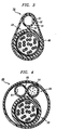
- FIG. 3 is an alternative embodiment in which an optical fiber duct is spaced from a metallic conductor portion;
- FIG. 4 is a still further embodiment which includes an optical fiber portion and a spare duct;
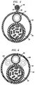
- FIG. 5 is an end view showing the basic structure of the hybrid cable of the invention, the cable including a self-supporting sheath system and which is suitable for aerial use, with which any of the cable configurations of Figs. 1 to 4 and 6 may be used; and
- FIG. 6 is an end view of an alternative embodiment which includes metallic conductors which may be used for the transmission of electrical power.
-
- Referring now to FIG. 1, there is shown a hybrid cable which is designated generally by the
numeral 20. Thecable 20 includes afirst transmission portion 22 which in a preferred embodiment may be a metallic conductor portion and a second transmission portion which in a preferred embodiment may be anoptical fiber portion 24. - The
metallic conductor portion 22 includes acore 30 which includes a plurality of pairs of insulated metallic conductors 32-32. Each of the insulated metallic conductors includes a longitudinally extendingmetallic conductor 34 and aninsulation cover 36. Theinsulation cover 36 may include one or more layers of insulation material such as one, for example, which is made of polyethylene. About the twisted pairs of metallic conductors is disposed acore wrap 38 which in a preferred embodiment is made of a plastic material such as polyester plastic material, for example. - It should be apparent that other materials may be used to provide the insulation covers 36-36. For example, should it be desired to extend the
cable 20 onto customers' premises, the insulation cover desirably is a flame retardant material such as a polyetherimide or other non-halogenated plastic material. - The
metallic conductor portion 22 of thecable 20 may also include waterblocking provisions. Disposed within interstices among the conductor pairs and between the conductor pairs and thecore wrap 38 is a fillingmaterial 40 which is waterblocking. Asuitable filling material 40 is one such as that disclosed and claimed in U. S. patent 4,870,117. - About the wrapped core is disposed a shielding system which may comprise one or more corrugated metallic shields. For example, the
cable 20 may include acorrugated aluminum shield 42 which has been wrapped about the core to form alongitudinal gapped seam 43 and acorrugated steel shield 44 which has been wrapped about the corrugated aluminum shield and which has a longitudinal overlappedseam 46. Of course, the seams may be offset circumferentially from each other. - Lastly, for the
metallic conductor portion 22, ajacket 48 which is made of a plastic material such a polyethylene encloses the shielding system. Of course, other suitable materials such as polypropylene or non-halogenated flame retardant materials may be used for thejacket 48. - The metallic conductor portion may include other waterblocking provisions. For example, a layer of a laminate which includes a superabsorbent material in powder form may be included in the sheath system. Further, yarn which has been treated with a superabsorbent material may be included in the sheath system or in the core. See, for example, U.S. patent 4,867,526 and U.S. patent 4,815,813.
- As is seen in FIG. 1, the
optical fiber portion 24 of thecable 20 includes provisions for receiving optical fiber transmission media such as anoptical fiber cable 50 which includes a plurality of optical fibers 51-51 (see FIG. 2). Such acable 50 may be one such as that disclosed in U.S. patent 4,844,575. Alongitudinally extending duct 52 is disposed outside thejacket 48 of themetallic conductor portion 22 and in a preferred embodiment is made of polyethylene. Other materials may be used for theduct 52. For example, if it is desired to extend the cable onto customers' premises, the duct may be made of a fluoropolymer or a non-halogenated material. - Instead of an
optical fiber cable 50 loose optical fiber may be installed in theduct 52. In that event, theduct 52 is sized so that an inner area defined by the inner diameter of the duct is sufficiently large to maintain a suitable packing ratio of the optical fibers 51-51 which may become disposed in the duct. By packing ratio is meant the ratio of the sum of the transverse cross-sectional areas of the optical fibers to the inner area defined by the inner diameter of the duct. A suitable ratio is in the range of about 0.1 to 0.5. - Holding the
metallic conductor portion 22 and theoptical fiber portion 24 together is anouter jacket 60. Theouter jacket 60 preferably is made of polyethylene, but for indoor uses may be a suitable flame retardant material. As is seen in FIG. 1, anouter jacket 60 engages a substantial portion of the circumference of thejacket 48 of themetallic conductor portion 22 and a portion of theduct 52. - Of course, when the
cable 20 is manufactured, the cable may not include optical fiber. What it does include are provisions for receiving optical fiber at a later time as the use of optical fiber can be justified economically. At a subsequent time, optical fiber may be installed in theduct 52 by the use of a pre-placed pullingtape 61 or by using the flow of air. ln the alternative, the fiber may be caused to become disposed in theduct 52 by the methods described and claimed in EP-A-0 520 683 which is not yet published and is not relevant to inventive step. - The
optical fiber portion 24 also may include waterbiocking provisions. For example, if optical fibers are disposed in theduct 52 either during manufacture of thecable 20 or subsequently, the duct may be filled with a waterbiocking material such as that disclosed in U.S. patent 5,187,763. - The
cable 20 of this invention which comprises the configuration shown in Fig.5, is advantageous from a number of standpoints. For example, accessing the optical fiber in thecable 20 is relatively easy; only theouter jacket 60 need be violated to reach theoptical fiber portion 24. Further, because theduct 52 may be used to receive an optical fiber cable, any suitably sized cable may be used, depending on specific needs. Also, themetallic conductor portion 22 may be a standard offering multipair cable. Further, the configuration is adaptable to various size ducts and various copper conductor cable sizes. Accordingly, the cables of this invention facilitate the marriage of optical fiber and metallic conductor cables, each having properties to meet specific needs. - Although the configuration of the cable in FIG. 1 is non-circular, a circular arrangement is achievable. Instead of extruding the
jacket 60 over theduct 52 and over themetallic conductor portion 22, the duct and the metallic conductor portions are enclosed in a circular metallic member 62 (see FIG. 2) which has been wrapped about the assembly of the duct and the metallic conductor portion. Themetallic member 62 is provided with an adhesive material such as an adhesive copolymer material on its outer major surface. Then anouter jacket 64 is extruded about the circular metallic member and becomes adhered thereto. - In the embodiments shown in FIGS. 1-2, the
optical fiber portion 24 is contiguous to an outer surface of themetallic conductor portion 22. In an alternative embodiment shown in FIG. 3 and designated generally by the numeral 70, theoptical fiber portion 24 is spaced from thejacket 48 of themetallic conductor portion 22 but connected thereto through aweb 72 of a plastic material which is the same plastic material of which theduct 52 and theouter jacket 48 are made. - A still further embodiment is depicted in FIG. 4. Therein, a hybrid cable designated generally by the
number 80 includes ametallic conductor portion 22, anoptical fiber portion 24 and aspare duct 82. In this embodiment, thecable 80 may include optical fibers 51-51 or anoptical fiber cable 50 disposed in theduct 52 whereas thespare duct 82 provides the capability of having additional fiber added thereto in the future. - The cable of this invention provides much flexibility in satisfying customers' needs. Reels of ducts and copper cables may be maintained in inventory in cable factories. As demand arises, a particular duct size may be joined to a particular copper cable size to customize the final product. A fixed size first transmission portion need not be attached permanently to a fixed size second transmission portion until a need is determined.
- Optical fiber may be caused to become positioned in the duct in the factory or in the field when the need arises. When a future installation of optical fiber is planned, the duct of the cable is supplied with a pull tape therein.
- Cables of this invention as shown in Fig. 5 also may be used aerially. As shown in FIG. 5, the cable of FIG. 2 is provided with an
aerial support portion 96. Theaerial support portion 96 includes a longitudinally extendingstrength member 97 enclosed in aplastic jacket 98. Thejacket 98 is connected to theplastic jacket 64 by aweb 99 of plastic material. - Also, as mentioned in the Background of the Invention, a hybrid cable desirably includes metallic conductors which may be used to transmit electrical power for any number of purposes. In FIG. 6 is depicted the cable of FIG. 2 with two transmission media 100-100 which are suitable for the transmission of electrical power.
- Cables of this invention are such as to be able to provide enhanced transmission capability to suit customers' needs. Further, various combinations of metallic conductor and/or optical fiber portions may be made. For example, in the configuration of FIG. 1, the first transmission portion need not be a metallic conductor portion but instead may be an optical fiber portion such as the
optical fiber cable 50, for example. The second transmission portion affords the capability of enhancing the optical fiber capacity of thecable 20 at a future date as the need arises. Also, although the first transmission portion is depicted as having a larger outer diameter than that of the second transmission portion, the reverse may be true or they may be equal in size. Further, if the first transmission portion includes metallic conductors, the metallic conductors at a future date may be used for transmitting electrical power as optical fiber transmission media are added to the duct.
Claims (9)
- A hybrid cable (2) which comprisesa first transmission portion (22) which comprises a sheath system which includes a plastic jacket (48);a second transmission portion (24) which includes a duct (52) which is made of plastic material and which is disposed outside of said jacket (48) of said first transmission portion (22);means comprising an outer plastic jacket (64) disposed about said first and second transmission portions (22,24) for holding together said first and second transmission portions (22,24); andan aerial support portion (96) which includes a longitudinally extending strength member (97) and which is connected to said outer jacket (64) by a web (99) made of plastic material,said aerial support portion (96) further including a jacket (98) which is disposed about said strength member (97) and is connected to said outer jacket (64) by said web (99).
- The hybrid cable (20) of claim 1, wherein said first transmission portion (22) is a metallic conductor portion which includes a plurality of twisted pairs of insulated metallic conductors (34) disposed within said sheath system and wherein said duct (52) is adapted to receive optical fiber transmission media (50).
- The hybrid cable (20) of claim 2, wherein said metallic conductor portion includes a core wrap (38) comprising a strip of plastic material which has been wrapped about said plurality of twisted pairs of insulated metallic conductors (34).
- The hybrid cable (20) of claim 3, wherein said metallic conductor portion also includes a shielding system (42) which is disposed between said plastic jacket (48) and said plurality of twisted pairs of insulated metallic conductors (34).
- The hybrid cable (20) of claim 2, wherein said duct (52) and said jacket (48) of said metallic conductor portion (22) are spaced apart and are joined by a plastic web (72) extending therebetween.
- The hybrid cable (20) of claim 1, wherein a longitudinally extending tape (61) is disposed within said duct (52) and is used to pull optical fiber or optical fiber cable (50) into the duct (52).
- The hybrid cable (20) of claim 1, wherein said cable includes two ducts (52,82), each of which is disposed outside of said jacket (48) of said first transmission portion (22).
- The hybrid cable (20) of claim 7, which also includes a plurality of optical fibers (51) which are disposed in one of said ducts (52,82).
- The hybrid cable (20) of claim 1, which also includes means (100) for transmitting electrical power.
Applications Claiming Priority (2)
| Application Number | Priority Date | Filing Date | Title |
|---|---|---|---|
| US856619 | 1986-04-25 | ||
| US85661992A | 1992-03-24 | 1992-03-24 |
Publications (3)
| Publication Number | Publication Date |
|---|---|
| EP0562770A2 EP0562770A2 (en) | 1993-09-29 |
| EP0562770A3 EP0562770A3 (en) | 1993-12-15 |
| EP0562770B1 true EP0562770B1 (en) | 1999-05-26 |
Family
ID=25324089
Family Applications (1)
| Application Number | Title | Priority Date | Filing Date |
|---|---|---|---|
| EP93302073A Expired - Lifetime EP0562770B1 (en) | 1992-03-24 | 1993-03-18 | Hybrid communications cable for enhancement of transmission capability |
Country Status (9)
| Country | Link |
|---|---|
| US (1) | US5448669A (en) |
| EP (1) | EP0562770B1 (en) |
| JP (1) | JPH06103833A (en) |
| KR (1) | KR100278728B1 (en) |
| CN (1) | CN1074158C (en) |
| CA (1) | CA2090053C (en) |
| DE (1) | DE69325046T2 (en) |
| ES (1) | ES2133146T3 (en) |
| MX (1) | MX9301549A (en) |
Families Citing this family (54)
| Publication number | Priority date | Publication date | Assignee | Title |
|---|---|---|---|---|
| GB2270992B (en) * | 1992-08-04 | 1995-12-20 | Pirelli General Plc | Cables having electrical conductors and optical fibres |
| US5606151A (en) * | 1993-03-17 | 1997-02-25 | Belden Wire & Cable Company | Twisted parallel cable |
| US6222129B1 (en) | 1993-03-17 | 2001-04-24 | Belden Wire & Cable Company | Twisted pair cable |
| AU4197796A (en) * | 1994-11-14 | 1996-06-06 | New Media Corp. | Shielded audio/digital communication cable system |
| US5883334A (en) * | 1995-06-13 | 1999-03-16 | Alcatel Na Cable Systems, Inc. | High speed telecommunication cable |
| JPH1068849A (en) * | 1996-08-29 | 1998-03-10 | Tokin Corp | Fiber optic cable |
| DE19641616B4 (en) * | 1996-10-09 | 2007-07-19 | CCS Technology, Inc., Wilmington | Communication cable with strain relief elements attached in the area of the outer jacket |
| US5905834A (en) * | 1997-07-21 | 1999-05-18 | Pirelli Cable Corporation | Combination loose tube optical fiber cable with reverse oscillating lay |
| US6091025A (en) | 1997-07-29 | 2000-07-18 | Khamsin Technologies, Llc | Electrically optimized hybird "last mile" telecommunications cable system |
| US6684030B1 (en) | 1997-07-29 | 2004-01-27 | Khamsin Technologies, Llc | Super-ring architecture and method to support high bandwidth digital “last mile” telecommunications systems for unlimited video addressability in hub/star local loop architectures |
| US6114632A (en) * | 1998-03-05 | 2000-09-05 | Planas, Sr.; Alberto E. | Integrated power and data communication hybrid cable assembly for local area computer network |
| US6195487B1 (en) | 1998-06-30 | 2001-02-27 | Pirelli Cable Corporation | Composite cable for access networks |
| US6239379B1 (en) | 1998-07-29 | 2001-05-29 | Khamsin Technologies Llc | Electrically optimized hybrid “last mile” telecommunications cable system |
| US6275644B1 (en) * | 1998-12-15 | 2001-08-14 | Transmatic, Inc. | Light fixture including light pipe having contoured cross-section |
| US6185351B1 (en) | 1999-10-15 | 2001-02-06 | Lucent Technologies, Inc. | All-dielectric, self-supporting, loose-tube cable with optical fiber ribbons |
| US6519391B2 (en) * | 2000-06-12 | 2003-02-11 | Lextron Systems, Inc. | Multiple methods and systems for connecting or tapping into fiber optics |
| WO2002012943A1 (en) | 2000-08-07 | 2002-02-14 | Pirelli General Plc | Optical fibre cable |
| BRPI0206428B1 (en) * | 2001-11-19 | 2017-11-28 | Prysmian Cables & Systems Limited | FIBER OPTICAL TRANSMISSION CABLE FOR SUSPENSION INSTALLATION, AND TRANSMISSION INSTALLATION |
| US7027697B2 (en) * | 2001-12-28 | 2006-04-11 | Pirelli Communications Cables And Systems Usa, Llc | Cable having conduits for receiving optical fibers |
| CN103124189A (en) | 2003-07-11 | 2013-05-29 | 泛达公司 | Alien crosstalk suppression with enhanced patch cord |
| US7220067B2 (en) * | 2004-03-24 | 2007-05-22 | Schlumberger Technology Corporation | Cable splice protector |
| KR20050121933A (en) * | 2004-06-23 | 2005-12-28 | 엘에스전선 주식회사 | Cable impregnated loosed tube type optical fiber and power wire |
| US7208684B2 (en) * | 2004-07-30 | 2007-04-24 | Ulectra Corporation | Insulated, high voltage power cable for use with low power signal conductors in conduit |
| US6998538B1 (en) | 2004-07-30 | 2006-02-14 | Ulectra Corporation | Integrated power and data insulated electrical cable having a metallic outer jacket |
| US7317163B2 (en) | 2004-12-16 | 2008-01-08 | General Cable Technology Corp. | Reduced alien crosstalk electrical cable with filler element |
| US7157644B2 (en) | 2004-12-16 | 2007-01-02 | General Cable Technology Corporation | Reduced alien crosstalk electrical cable with filler element |
| US7064277B1 (en) | 2004-12-16 | 2006-06-20 | General Cable Technology Corporation | Reduced alien crosstalk electrical cable |
| US7238885B2 (en) * | 2004-12-16 | 2007-07-03 | Panduit Corp. | Reduced alien crosstalk electrical cable with filler element |
| CN100386824C (en) * | 2005-09-07 | 2008-05-07 | 上海乐庭电线工业有限公司 | Multimedia combination cable for elevator |
| US7271344B1 (en) * | 2006-03-09 | 2007-09-18 | Adc Telecommunications, Inc. | Multi-pair cable with channeled jackets |
| US20080013956A1 (en) * | 2006-07-14 | 2008-01-17 | Tenvera, Inc. | Provisioning of Services Via an Optical Fiber Network |
| US20080011990A1 (en) * | 2006-07-14 | 2008-01-17 | Tenvera, Inc. | Installation of Fiber Optic Cables |
| US20080011514A1 (en) * | 2006-07-14 | 2008-01-17 | Tenvera, Inc. | Optical Fiber Distribution Apparatus and Method |
| US20080013909A1 (en) * | 2006-07-14 | 2008-01-17 | Tenvera, Inc. | Modular Optical Fiber Network Interface |
| US20080013957A1 (en) * | 2006-07-14 | 2008-01-17 | Tenvera, Inc. | Service Aggregation Gateway |
| US20080013907A1 (en) * | 2006-07-14 | 2008-01-17 | Tenvera, Inc. | Optical Fiber Blowing Device and Method |
| US20080013893A1 (en) * | 2006-07-14 | 2008-01-17 | Tenvera, Inc. | Optical Fiber Ferrule and Ferrule Receiver, and Method for Manufacturing the Same |
| BRPI0707034A2 (en) * | 2006-08-30 | 2011-04-12 | Afl Telecommunications Llc | method of manufacturing one cable, cable, double-tube down-cable and multi-tube down-cable |
| US8089000B2 (en) * | 2007-10-12 | 2012-01-03 | General Cable Technologies Corporation | Waterproof data cable with foam filler and water blocking material |
| JP4966230B2 (en) * | 2008-03-11 | 2012-07-04 | 住友電設株式会社 | Underground shopping center AM broadcast retransmission system |
| WO2010065632A1 (en) * | 2008-12-02 | 2010-06-10 | Corning Cable Systems Llc | Optical fiber array cables and associated fiber optic cables and systems |
| DK2549318T3 (en) * | 2011-07-18 | 2018-06-18 | Wavin Bv | Multi-pipe system for a cable |
| US9523832B2 (en) * | 2012-03-23 | 2016-12-20 | Afl Telecommunications Llc | High temperature, zero fiber strain, fiber optic cable |
| US9679681B2 (en) * | 2012-04-27 | 2017-06-13 | Corning Optical Communications LLC | Hybrid cable including fiber-optic and electrical-conductor elements |
| CN102903436A (en) * | 2012-08-15 | 2013-01-30 | 无锡市东田电缆有限公司 | Novel aerial insulated cable |
| US9583923B2 (en) | 2013-03-15 | 2017-02-28 | Abl Ip Holding Llc | Class I and class II modular wiring system |
| EP3011376B1 (en) * | 2013-06-19 | 2017-04-12 | ABB HV Cables (Switzerland) GmbH | A tool for opening an extruded profiled body of a power cord assembly device |
| CN104810082A (en) * | 2014-01-23 | 2015-07-29 | 上海宏胜电线电缆有限公司 | Optical-electric cable capable of coaxially transmitting CATV signals and electric energy |
| GB2527580B (en) * | 2014-06-26 | 2021-07-21 | British Telecomm | Installation of cable connections |
| CN106098196B (en) * | 2016-07-06 | 2018-04-13 | 芜湖航天特种电缆厂股份有限公司 | Low loss coaxial radio frequency cable and preparation method thereof |
| WO2018141681A1 (en) | 2017-02-01 | 2018-08-09 | British Telecommunications Public Limited Company | Optical fibre event location |
| WO2019016263A1 (en) | 2017-07-20 | 2019-01-24 | British Telecommunications Public Limited Company | Optical fibre |
| CN114420351A (en) * | 2022-01-21 | 2022-04-29 | 富通集团有限公司 | An optoelectronic composite cable for underwater applications |
| US20240221976A1 (en) * | 2022-12-30 | 2024-07-04 | Ppc Broadband, Inc. | Hybrid power cable with microduct configured to receive fiber optic cable at an installation site so as to avoid installation of unneeded fiber optic cable |
Family Cites Families (22)
| Publication number | Priority date | Publication date | Assignee | Title |
|---|---|---|---|---|
| SE403409B (en) * | 1976-08-24 | 1978-08-14 | Ericsson Telefon Ab L M | SELF-FLOATING CABLE WITH GREAT FLEXIBILITY PREFERABLY FOR MARINE OPERATIONS |
| CA1112310A (en) * | 1977-05-13 | 1981-11-10 | Peter Fearns | Overhead electric transmission systems |
| JPS5686012A (en) * | 1979-12-14 | 1981-07-13 | Nippon Telegraph & Telephone | Cable protecting tube |
| DE3015732C2 (en) * | 1980-04-24 | 1983-06-01 | Philips Kommunikations Industrie AG, 8500 Nürnberg | Overhead cable with optical fibers arranged in its interior |
| US4365865A (en) * | 1981-01-30 | 1982-12-28 | Sea-Log Corporation | Hybrid cable construction |
| GB2107896B (en) * | 1981-10-20 | 1985-04-03 | Standard Telephones Cables Ltd | Electric cable |
| JPS5995304U (en) * | 1982-12-18 | 1984-06-28 | 東北電力株式会社 | Non-metallic self-supporting aerial optical cable |
| US4552432A (en) * | 1983-04-21 | 1985-11-12 | Cooper Industries, Inc. | Hybrid cable |
| DE3316898A1 (en) * | 1983-05-09 | 1984-11-15 | Siemens AG, 1000 Berlin und 8000 München | Self-supporting optical fibre cable and method for its production |
| FR2547066A1 (en) * | 1983-06-03 | 1984-12-07 | Cables De Lyon Geoffroy Delore | OPTICAL FIBER SUBMARINE CABLE AND METHOD OF MANUFACTURING SUCH A CABLE |
| JPH0669250B2 (en) * | 1984-02-23 | 1994-08-31 | 住友電気工業株式会社 | Optical cable laying method using self-supporting Daruma type overhead cable conduit |
| JPS60206462A (en) * | 1984-03-30 | 1985-10-18 | Canyon Corp | manual dispenser |
| US4563540A (en) * | 1984-06-29 | 1986-01-07 | At&T Technologies, Inc. | Bonded sheath cable |
| US4856867A (en) * | 1984-09-10 | 1989-08-15 | Gaylin Wayne L | Carrier cable, fiber optic cable, and sheath support assembly |
| GB8427895D0 (en) * | 1984-11-05 | 1984-12-12 | Telephone Cables Ltd | Optical cables |
| US4815813A (en) * | 1987-10-30 | 1989-03-28 | American Telephone And Telegraph Company | Water resistant communications cable |
| US4873393A (en) * | 1988-03-21 | 1989-10-10 | American Telephone And Telegraph Company, At&T Bell Laboratories | Local area network cabling arrangement |
| GB8905738D0 (en) * | 1989-03-14 | 1989-04-26 | Bicc Plc | Composite aerial cable |
| US5039195A (en) * | 1990-05-29 | 1991-08-13 | At&T Bell Laboratories | Composite cable including portions having controlled flexural rigidities |
| CA2017878C (en) * | 1990-05-30 | 1994-03-29 | Kazuya Abe | Composite overhead cable structure having high seal properties and a process for producing the same |
| EP0467294A1 (en) * | 1990-07-19 | 1992-01-22 | Alcatel Cable | Submarine telecommunication cable with optical fibres inside à tube |
| US5189718A (en) * | 1991-04-02 | 1993-02-23 | Siecor Corporation | Composite cable containing light waveguides and electrical conductors |
-
1993
- 1993-02-22 CA CA002090053A patent/CA2090053C/en not_active Expired - Fee Related
- 1993-03-18 ES ES93302073T patent/ES2133146T3/en not_active Expired - Lifetime
- 1993-03-18 EP EP93302073A patent/EP0562770B1/en not_active Expired - Lifetime
- 1993-03-18 DE DE69325046T patent/DE69325046T2/en not_active Expired - Fee Related
- 1993-03-19 KR KR1019930004236A patent/KR100278728B1/en not_active Expired - Fee Related
- 1993-03-19 MX MX9301549A patent/MX9301549A/en not_active IP Right Cessation
- 1993-03-23 CN CN93103289A patent/CN1074158C/en not_active Expired - Fee Related
- 1993-03-24 JP JP5087838A patent/JPH06103833A/en active Pending
- 1993-12-21 US US08/171,885 patent/US5448669A/en not_active Expired - Fee Related
Also Published As
| Publication number | Publication date |
|---|---|
| JPH06103833A (en) | 1994-04-15 |
| CN1074158C (en) | 2001-10-31 |
| CN1079579A (en) | 1993-12-15 |
| KR100278728B1 (en) | 2001-01-15 |
| US5448669A (en) | 1995-09-05 |
| EP0562770A3 (en) | 1993-12-15 |
| CA2090053C (en) | 1997-10-28 |
| DE69325046T2 (en) | 1999-10-21 |
| MX9301549A (en) | 1994-07-29 |
| KR930020495A (en) | 1993-10-19 |
| EP0562770A2 (en) | 1993-09-29 |
| DE69325046D1 (en) | 1999-07-01 |
| ES2133146T3 (en) | 1999-09-01 |
| CA2090053A1 (en) | 1993-09-25 |
Similar Documents
| Publication | Publication Date | Title |
|---|---|---|
| CA2090053C (en) | Hybrid communications cable for enhancement of transmission capability | |
| AU728335B2 (en) | Combination optical fiber cable | |
| EP1223448B1 (en) | Optical fibre cable with support member for indoor and outdoor use | |
| CA2242707C (en) | Combination optical fiber cable | |
| US5740295A (en) | Low fiber count optical cable | |
| US6137935A (en) | Method for fabricating an optical cable | |
| US5913003A (en) | Composite fiber optic distribution cable | |
| CA2034629C (en) | Optical fiber cable with single buffer tube | |
| CA1091071A (en) | Fiber optic cable and method of making same | |
| US6343172B1 (en) | Composite fiber optic/coaxial electrical cables | |
| US5229851A (en) | Optical fiber cable with large number of ribbon units containing optical fibers and enclosed in tubes | |
| US4257675A (en) | Optical-fiber submarine cable and manufacturing method thereof | |
| AU748474B2 (en) | Composite cable for access networks | |
| EP1591814B1 (en) | High count optical fiber cable | |
| EP0454433A2 (en) | Optical fiber service cable | |
| US6681071B2 (en) | Dry core indoor/outdoor fiber optic cable | |
| CA2255175A1 (en) | Fiber optic cable | |
| CA2051055A1 (en) | Electro-optical overhead cable with 24 and more light wave guides | |
| US4688888A (en) | Optical cable | |
| US5777260A (en) | Coaxial cable additionally having at least one light waveguide | |
| US20040184749A1 (en) | Fiber optic cable and method of manufacturing same | |
| EP4571381A2 (en) | Optical fiber ribbon cable | |
| NZ202121A (en) | Optical fibre duct enclosed by embedded wires | |
| GB2129580A (en) | Optical fibre cable | |
| JP2877915B2 (en) | Connection structure of optical fiber composite submarine cable |
Legal Events
| Date | Code | Title | Description |
|---|---|---|---|
| PUAI | Public reference made under article 153(3) epc to a published international application that has entered the european phase |
Free format text: ORIGINAL CODE: 0009012 |
|
| AK | Designated contracting states |
Kind code of ref document: A2 Designated state(s): DE ES FR GB IT NL |
|
| PUAL | Search report despatched |
Free format text: ORIGINAL CODE: 0009013 |
|
| AK | Designated contracting states |
Kind code of ref document: A3 Designated state(s): DE ES FR GB IT NL |
|
| RAP3 | Party data changed (applicant data changed or rights of an application transferred) |
Owner name: AT&T CORP. |
|
| 17P | Request for examination filed |
Effective date: 19940603 |
|
| 17Q | First examination report despatched |
Effective date: 19950705 |
|
| GRAG | Despatch of communication of intention to grant |
Free format text: ORIGINAL CODE: EPIDOS AGRA |
|
| GRAG | Despatch of communication of intention to grant |
Free format text: ORIGINAL CODE: EPIDOS AGRA |
|
| GRAH | Despatch of communication of intention to grant a patent |
Free format text: ORIGINAL CODE: EPIDOS IGRA |
|
| GRAH | Despatch of communication of intention to grant a patent |
Free format text: ORIGINAL CODE: EPIDOS IGRA |
|
| GRAA | (expected) grant |
Free format text: ORIGINAL CODE: 0009210 |
|
| AK | Designated contracting states |
Kind code of ref document: B1 Designated state(s): DE ES FR GB IT NL |
|
| ITF | It: translation for a ep patent filed | ||
| REF | Corresponds to: |
Ref document number: 69325046 Country of ref document: DE Date of ref document: 19990701 |
|
| ET | Fr: translation filed | ||
| REG | Reference to a national code |
Ref country code: ES Ref legal event code: FG2A Ref document number: 2133146 Country of ref document: ES Kind code of ref document: T3 |
|
| PLBE | No opposition filed within time limit |
Free format text: ORIGINAL CODE: 0009261 |
|
| STAA | Information on the status of an ep patent application or granted ep patent |
Free format text: STATUS: NO OPPOSITION FILED WITHIN TIME LIMIT |
|
| 26N | No opposition filed | ||
| PGFP | Annual fee paid to national office [announced via postgrant information from national office to epo] |
Ref country code: ES Payment date: 20010302 Year of fee payment: 9 |
|
| PGFP | Annual fee paid to national office [announced via postgrant information from national office to epo] |
Ref country code: NL Payment date: 20010312 Year of fee payment: 9 |
|
| PGFP | Annual fee paid to national office [announced via postgrant information from national office to epo] |
Ref country code: DE Payment date: 20010330 Year of fee payment: 9 |
|
| REG | Reference to a national code |
Ref country code: GB Ref legal event code: IF02 |
|
| PG25 | Lapsed in a contracting state [announced via postgrant information from national office to epo] |
Ref country code: ES Free format text: LAPSE BECAUSE OF NON-PAYMENT OF DUE FEES Effective date: 20020319 |
|
| PG25 | Lapsed in a contracting state [announced via postgrant information from national office to epo] |
Ref country code: NL Free format text: LAPSE BECAUSE OF NON-PAYMENT OF DUE FEES Effective date: 20021001 Ref country code: DE Free format text: LAPSE BECAUSE OF NON-PAYMENT OF DUE FEES Effective date: 20021001 |
|
| NLV4 | Nl: lapsed or anulled due to non-payment of the annual fee |
Effective date: 20021001 |
|
| PGFP | Annual fee paid to national office [announced via postgrant information from national office to epo] |
Ref country code: FR Payment date: 20030304 Year of fee payment: 11 |
|
| PGFP | Annual fee paid to national office [announced via postgrant information from national office to epo] |
Ref country code: GB Payment date: 20030312 Year of fee payment: 11 |
|
| PG25 | Lapsed in a contracting state [announced via postgrant information from national office to epo] |
Ref country code: GB Free format text: LAPSE BECAUSE OF NON-PAYMENT OF DUE FEES Effective date: 20040318 |
|
| REG | Reference to a national code |
Ref country code: ES Ref legal event code: FD2A Effective date: 20030410 |
|
| GBPC | Gb: european patent ceased through non-payment of renewal fee |
Effective date: 20040318 |
|
| PG25 | Lapsed in a contracting state [announced via postgrant information from national office to epo] |
Ref country code: FR Free format text: LAPSE BECAUSE OF NON-PAYMENT OF DUE FEES Effective date: 20041130 |
|
| REG | Reference to a national code |
Ref country code: FR Ref legal event code: ST |
|
| PG25 | Lapsed in a contracting state [announced via postgrant information from national office to epo] |
Ref country code: IT Free format text: LAPSE BECAUSE OF NON-PAYMENT OF DUE FEES;WARNING: LAPSES OF ITALIAN PATENTS WITH EFFECTIVE DATE BEFORE 2007 MAY HAVE OCCURRED AT ANY TIME BEFORE 2007. THE CORRECT EFFECTIVE DATE MAY BE DIFFERENT FROM THE ONE RECORDED. Effective date: 20050318 |