EP0562723A2 - Self powered portable computer - Google Patents
Self powered portable computer Download PDFInfo
- Publication number
- EP0562723A2 EP0562723A2 EP93301488A EP93301488A EP0562723A2 EP 0562723 A2 EP0562723 A2 EP 0562723A2 EP 93301488 A EP93301488 A EP 93301488A EP 93301488 A EP93301488 A EP 93301488A EP 0562723 A2 EP0562723 A2 EP 0562723A2
- Authority
- EP
- European Patent Office
- Prior art keywords
- housing
- battery pack
- unit
- rechargeable batteries
- portable computer
- Prior art date
- Legal status (The legal status is an assumption and is not a legal conclusion. Google has not performed a legal analysis and makes no representation as to the accuracy of the status listed.)
- Granted
Links
Images



Classifications
-
- G—PHYSICS
- G06—COMPUTING OR CALCULATING; COUNTING
- G06F—ELECTRIC DIGITAL DATA PROCESSING
- G06F1/00—Details not covered by groups G06F3/00 - G06F13/00 and G06F21/00
- G06F1/16—Constructional details or arrangements
- G06F1/1613—Constructional details or arrangements for portable computers
- G06F1/1633—Constructional details or arrangements of portable computers not specific to the type of enclosures covered by groups G06F1/1615 - G06F1/1626
- G06F1/1637—Details related to the display arrangement, including those related to the mounting of the display in the housing
- G06F1/1647—Details related to the display arrangement, including those related to the mounting of the display in the housing including at least an additional display
- G06F1/165—Details related to the display arrangement, including those related to the mounting of the display in the housing including at least an additional display the additional display being small, e.g. for presenting status information
-
- G—PHYSICS
- G06—COMPUTING OR CALCULATING; COUNTING
- G06F—ELECTRIC DIGITAL DATA PROCESSING
- G06F1/00—Details not covered by groups G06F3/00 - G06F13/00 and G06F21/00
- G06F1/16—Constructional details or arrangements
- G06F1/1613—Constructional details or arrangements for portable computers
- G06F1/1615—Constructional details or arrangements for portable computers with several enclosures having relative motions, each enclosure supporting at least one I/O or computing function
- G06F1/1616—Constructional details or arrangements for portable computers with several enclosures having relative motions, each enclosure supporting at least one I/O or computing function with folding flat displays, e.g. laptop computers or notebooks having a clamshell configuration, with body parts pivoting to an open position around an axis parallel to the plane they define in closed position
-
- G—PHYSICS
- G06—COMPUTING OR CALCULATING; COUNTING
- G06F—ELECTRIC DIGITAL DATA PROCESSING
- G06F1/00—Details not covered by groups G06F3/00 - G06F13/00 and G06F21/00
- G06F1/16—Constructional details or arrangements
- G06F1/1613—Constructional details or arrangements for portable computers
- G06F1/1633—Constructional details or arrangements of portable computers not specific to the type of enclosures covered by groups G06F1/1615 - G06F1/1626
- G06F1/1635—Details related to the integration of battery packs and other power supplies such as fuel cells or integrated AC adapter
-
- G—PHYSICS
- G06—COMPUTING OR CALCULATING; COUNTING
- G06F—ELECTRIC DIGITAL DATA PROCESSING
- G06F1/00—Details not covered by groups G06F3/00 - G06F13/00 and G06F21/00
- G06F1/16—Constructional details or arrangements
- G06F1/1613—Constructional details or arrangements for portable computers
- G06F1/1633—Constructional details or arrangements of portable computers not specific to the type of enclosures covered by groups G06F1/1615 - G06F1/1626
- G06F1/1656—Details related to functional adaptations of the enclosure, e.g. to provide protection against EMI, shock, water, or to host detachable peripherals like a mouse or removable expansions units like PCMCIA cards, or to provide access to internal components for maintenance or to removable storage supports like CDs or DVDs, or to mechanically mount accessories
-
- G—PHYSICS
- G06—COMPUTING OR CALCULATING; COUNTING
- G06F—ELECTRIC DIGITAL DATA PROCESSING
- G06F1/00—Details not covered by groups G06F3/00 - G06F13/00 and G06F21/00
- G06F1/16—Constructional details or arrangements
- G06F1/1613—Constructional details or arrangements for portable computers
- G06F1/1633—Constructional details or arrangements of portable computers not specific to the type of enclosures covered by groups G06F1/1615 - G06F1/1626
- G06F1/1662—Details related to the integrated keyboard
- G06F1/1671—Special purpose buttons or auxiliary keyboards, e.g. retractable mini keypads, keypads or buttons that remain accessible at closed laptop
-
- G—PHYSICS
- G06—COMPUTING OR CALCULATING; COUNTING
- G06F—ELECTRIC DIGITAL DATA PROCESSING
- G06F1/00—Details not covered by groups G06F3/00 - G06F13/00 and G06F21/00
- G06F1/16—Constructional details or arrangements
- G06F1/20—Cooling means
- G06F1/203—Cooling means for portable computers, e.g. for laptops
-
- H—ELECTRICITY
- H01—ELECTRIC ELEMENTS
- H01M—PROCESSES OR MEANS, e.g. BATTERIES, FOR THE DIRECT CONVERSION OF CHEMICAL ENERGY INTO ELECTRICAL ENERGY
- H01M50/00—Constructional details or processes of manufacture of the non-active parts of electrochemical cells other than fuel cells, e.g. hybrid cells
- H01M50/20—Mountings; Secondary casings or frames; Racks, modules or packs; Suspension devices; Shock absorbers; Transport or carrying devices; Holders
- H01M50/204—Racks, modules or packs for multiple batteries or multiple cells
- H01M50/207—Racks, modules or packs for multiple batteries or multiple cells characterised by their shape
- H01M50/213—Racks, modules or packs for multiple batteries or multiple cells characterised by their shape adapted for cells having curved cross-section, e.g. round or elliptic
-
- Y—GENERAL TAGGING OF NEW TECHNOLOGICAL DEVELOPMENTS; GENERAL TAGGING OF CROSS-SECTIONAL TECHNOLOGIES SPANNING OVER SEVERAL SECTIONS OF THE IPC; TECHNICAL SUBJECTS COVERED BY FORMER USPC CROSS-REFERENCE ART COLLECTIONS [XRACs] AND DIGESTS
- Y02—TECHNOLOGIES OR APPLICATIONS FOR MITIGATION OR ADAPTATION AGAINST CLIMATE CHANGE
- Y02E—REDUCTION OF GREENHOUSE GAS [GHG] EMISSIONS, RELATED TO ENERGY GENERATION, TRANSMISSION OR DISTRIBUTION
- Y02E60/00—Enabling technologies; Technologies with a potential or indirect contribution to GHG emissions mitigation
- Y02E60/10—Energy storage using batteries
Definitions
- the present invention relates to a self-powered portable computer comprising a base unit, an electronic unit contained inside the base unit and having a plurality of electronics components and two power supply conductors for the elctronic unit, in which the base unit comprises a housing able to house a battery pack having two terminals which can be connected to the two power supply conductors in order to power the electronic unit and in which the battery pack comprises a case containing rechargeable batteries.
- a portable computer of this type is known from European Patent Application No. 0419177, in which, in order to recharge the batteries, the battery pack has to be removed from the computer and the batteries recharged using a special recharging device. Moreover, this computer does not offer the option of using individual, non-rechargeable batteries. Its scope for use is thus limited, for example when once the batteries have run down, a second battery pack containing charged batteries is unavailable.
- Preferred embodiments of the present invention provide a portable computer which can be powered reliably using a pack of rechargeable batteries, using an external power unit for recharging the battery packs, and which also offers the option of using commercially available, non-rechargeable batteries.
- One preferred embodiment of the present invention provides a portable computer which is characterised by a power supply control circuit connected to its power supply conductors in order to power the electronic components with suitable voltages, and a recharging circuit to generate a given recharging current.
- the computer also comprises a power socket which can be connected to an external power unit in order to power the control circuit, and activate the recharging circuit and to a sensor device which can detect the presence of the battery pack in the housing of the base unit, so as to make the recharging current of the power supply control circuit available to the rechargeable batteries.
- the housing of the base unit can house a plurality of single non-rechargeable batteries as an alternative to the battery pack, and the sensor device does not respond to the presence of single batteries in the said housing and thus damaging attempts at recharging the non-rechargeable batteries are prevented.
- the housing of the base unit can carry intermediate conductors which suitably correct the non-rechargeable batteries together and to the power supply conductors.
- the self-powered portable computer indicated as a shown by the reference 31, comprises a base unit 32, a lid 33 which is hinged onto the base unit 32 and can be positioned between a closed configuration and an open configuration, an electronic unit 34 housed inside the base unit 32, a keyboard 36 for controlling the electronic unit 34 and a display screen 37 carried by the lid 33.
- the base unit 32 has a substantially parallelepipedal, somewhat flattened, shape and has an upper surface 38 which is horizontal in use, a bottom 39, a front part 40, a rear part 41, a right side 42 and a left side 43.
- the lid 33 has a front surrface 44 and the screen 37 is of the flat type and covers most of the front surface 44.
- the lid 33 in its closed configuration, superimposes the surface 44 over the upper surface 38 of the base unit 32. In its open configuration, the lid 33 is substantially vertical, allowing access to the keyboard 36 and enabling the display screen 37 to be seen.
- a mode indicator 46 for displaying characters and symbols indicating various operational states of the computer 31, is carried in the base unit 32.
- the lid 33 With regard to the lid 33, it comprises a viewing zone 47 in its lower part, external to the screen 37, so that the mode indicator 46 is still visible when the lid is in its closed configuration. Cables 45 in turn correct the electronic unit 34 inside the unit 32 to the screen 37, through a hinging zone between base unit 32 and the lid 33.
- the computer 31 is very compact, of the palm held type, having base dimensions equivalent to those of a notebook of standard A5 format, i.e. approximately 210 x 148 mm and a thickness of approximately 32mm in the closed configuration.
- the screen 37 is a 7'' screen of the reflecting liquid crystal type, equivalent to an active area of approximately 141 x 106mm and a graphics resolution of 640 x 400 dots.
- the mode indicator 46 has an active area of approximately 40 x 8.5 mm, enabling five graphic symbols and six alphanumeric characters to be displayed.
- the computer 31 On its left side 43, the computer 31 comprises a slot 54 with a connector 56 for data and program exchange using a microprocessor (IC) card 57, for example of the PCMCIA 1.0/JEID4 4.0 type, conforming to standards.
- IC microprocessor
- the computer 31 On its right side 42 also, the computer 31 comprises a parallel connector 58 and a series connector 59 (RS-232 type) for data exchange via external lines, with external peripherals or sources such as modems, display devices, printers and memory units.
- the connectors 58 and 59 can be covered with a small lid 60.
- the electronic unit 34 comprises a central processing unit (CPU) 61, a main dynamic type memory (DRAM) 62, static type memories (SRAM) 63 and 64, read only memory (ROM) 66 and a programmable read only memory (PROM) 67.
- the unit 34 fruther comprises control circuits 68 and 69, for the screen 37 and for the data input/output lines respectively and a control and timing unit 71 for the memories 62, 63, 64, 66 and 67, for the control circits 68 and 69 and for the CPU 61.
- the CPU 61 for example consists of an NEC V300HL microprocessor, operating at 16 MHz.
- the DRAM 62 has a memory of one MByte and the SRAMs 63 and 64 are dedicated to the screen 37 and to the external lines and have a capacity of 32 and 128 kBytes respectively.
- the control circuit 68 is for example of the 82C426 type and the control circuit 69 is of the PCB7310 type.
- the DOS progams are permanently recorded on the ROM 66, whereas the BIOS programs are permanently on the PROM 67.
- the computer 31 also comprises a non-volatile bulk memory 83, for exchanging data with the electronic unit 34.
- This unit comprises for example a hard disk unit (HDU) 84, securely fitted inside the base unit 32.
- HDU hard disk unit
- Some keys 35 on the keyboard 36 are preset to access bulk memory 83, and the mode indicator 46 has a bulk memory symbol which can be displayed to indicate that the bulk memory has been activated by the electronic unit 34.
- a battery pack 87 comprising batteries 88 can be housed in the unit 32 and is capable of powering the electronic unit 34 via a power supply control circuit 89 in order to power the various functions of the computer 31.
- the control circuit 89 comprises a DC/DC converter 91 and a recharging control circuit 92 which is connected to the microprocessor 61 and defines reduced power and limited operational states of the computer 31 so as to limit energy consumption from the batteries 88 when some of the potential functions of the computer 31 are not being exploited.
- the charging control circuit 92 is connected to a main switch 94 which projects from upper surface 38 of the base unit 32 and can be actuated when the lid 33 is in its open configuration, in order to preset the electronic unit 34 for operational modes associated with the closed configuration of the lid 33.
- the batteries 88 are rechargeable and the computer 31 can be connected to an external power unit 93 so as to operate on an external power supply.
- the control circuit 92 also transmits signals to the mode indictor 46 so that it may display alphanumeric characters to represent the limited operational states preset by the circuit 92.
- a graphic symbol representing a battery can further be activated by the circuit 92 on the indicator 46 to display that there is an insufficient charge in the power supply.
- the lid 33 has a surface 96, on the opposite side from the surface 44, which is accesible from the outside when the lid 33 is in the closed configuration.
- the surface 96 carries six presetting keys 97 which are connected to the electronic unit 34 via the cables 45 and can be actuated by an operator in order to preset some of the operational states of computer 31, when the lid 33 is in the closed configuration.
- the computer 31 also comprises a voice input/output unit 101, selection means 102 for selecting a voice-command state of the abovementioned computer for processing vocal commands, and presetting means comprising the presetting keys 97 to preset the different operational conditions of the electronic unit 34 in the voice-command state.
- the electronic unit 34 in turn comprises a conversion unit 107 to sample the analog signals coming from a microphone 103 in the voice input/output unit 101 in reply to the vocal commands received and convert them into digital signals which can be processed by other circuits in the same unit 34.
- the conversion unit 107 is also able to convert digital signals coming from other circuits in the electronic unit 34 into analog signals to be reproduced, as sounds, by a speaker 104 in the unit 101.
- the vocal commands, in the digital form as processed by the unit 104 are in turn stored in memory by the HDU unit 84, or by the IC card 57.
- the presetting keys 97 comprise a PLAY key 116 to playback vocal commands, an FF key 117 to fast forward the point of play-back in the memory, a STOP key 113 to put the computer 31 into a state of rest, an RW key 111 to fast rewind the point of the play-back, a REC key 114 to record a vocal command from that point in the memory and a PAUSE key 112 to stop recording or play-back, in a way similar to the way in which a magnetic tape recorder/player is operated.
- the batteries 88 in the battery pack 87 are located and enclosed in a case 151 which can be housed in a housing 152 in the base unit 32.
- the battery pack 87 comprises two terminals 153 and 154 which can be connected to two power supply conductors 156 and 157 to power the power supply control circuit 89 and the electronic unit 34, via two input terminals.
- a socket 158 connected to external power supply conductors 166 and 167 can be connected, via a conventional jack plug 159 and a cable 161, to the external power unit 93 in order to power the power supply control circuit 89.
- the conductors 157 and 167 are connected to a common earth for the various circuits of the electronic unit 34.
- the charging control circuit 92 also comprises a recharging circuit 160 which can generate the recharging current for the batteries 88 when the control circuit 92 is powered externally.
- a sensor device 162 can detect the presence of the case 151 in the housing 152, so as to make the circuit 160 recharging current available to the rechargeable batteries 88, through the conductors 156 and 157.
- the housing 152 can also house a series of single, non-rechargeable, AA-size batteries 163, as an alternative to the case 151.
- Intermediate conductors, indicated as a whole by the reference 164, are located in the housing 152 and are suitably connected together so as to connect the non-rechargeable batteries 163 in series.
- the power supply conductors 156 and 157 can in turn be connected to the opposite pole of the first and last batteries 163 in order to power the power supply control circuit 89 in the absence of the case 151.
- the sensor device 162 on the other hand, cannot detect the presence of the single batteries 163 and prevents hazardous attempts at recharging the non-rechargeable batteries 163.
- the external power unit 93 and the batteries 88 or 163 are each connected via a diode, 168 and 169 respectively, to an input terminal 165 of the DC/DC conveter 91 and across the power supply conductors 166 and 156.
- the sensor device 162 controls a microswitch 170 which is connected between the charging control circuit 92 generator 160 and the power supply conductor 156, which in turn is connected to the rechargeable batteries 88.
- the device 162 in particular consists of a lever for controlling the microswitch 170, which lever can interact with a shoulder 171 on the case 151 so as to be closed when the case 151 is housed in the housing 152.
- the power unit 93 When the power unit 93 is connected to the mains, it can recharge the set of batteries 88 via the recharging control circuit 92, through its current generator 160 and the microswitch 170.
- the case 151 consists of a plastic body which is parallelepipedal in shape and hollow in order to house the rechargeable batteries 88.
- the batteries 88 are cylinder NiCd batteries, substantially AA-size, and have a positive pole formed by a projecting cap and a negative pole formed by a metal base.
- the six batteries 88 are connected together in series by five thin conductive strips 172, each of which is soldered between the projecting cap of one battery and the base of the adjacent battery, in a manner known per se.
- the terminal 153 of the battery pack 87 consists of the projecting cap of the first battery 88 positioned at one end of the case 151 and the terminal 154 consists of the base of the last battery 88 positioned at the other end of the case 151.
- the two terminals 153 and 154 are arranged on the same face of the battery pack 87 and the case 151 comprises grooves 173 in which the conductive strips 172 which connect the rechargeable batteries 88 in series are housed.
- Two through holes 174 and 176 enable the terminals 153 and 154 to make contact with the single springs 179 and 180 of the power supply conductors 156 and 157, which springs are shaped so as to make contact only with the projecting cap of the first battery 88 and the base of the last battery 88 respectively.
- the housing 152 of the base unit 32 is of rectangular cross section and is delimited by the rear wall 41, by an inner wall 178 which is parallel to the wall 41 and by a bottom 175.
- a slit 177 has been made in the wall 178, in front of the control lever of the microswitch 170.
- the shoulder 171 on the case 161 expediently consists of a peg 155 which has a rectangular cross section and projects from the same face as the through holes 174 and 176 in order to pass through the slit 177 in the wall 178 and actuate the microswitch 170.
- the intermediate conductors 164 comprise three strip contacts 181 and four springs 182, 183, 184 and 186 which are connected together in pairs.
- the three strip contacts 181 are identical, each consisting of a metal strip having two small projecting plates 187 and are positioned in suitable grooves 188 in the rear wall 41.
- the grooves 188 are spaced apart from each other and the plates 18 project towards the inside of the housing 152.
- the two single springs 179 and 180 are in turn positioned in suitable grooves 189 and 191 arranged at each end of the inner wall 178.
- the four springs 182, 183, 184 and 186 are electrically connected in pairs so as to make up two pairs of springs, each pair positioned in a groove 192, 193 of the inner wall 178.
- the springs 183 and 186 are shaped so that they make contact only with the positive poles of the batteries 163.
- the grooves 192 and 193 are spaced part from each other along the inner wall 178 and between the grooves 189 and 191 of the single springs 179 and 180.
- the single springs 179 and 180, the double springs 182, 183 and 184, 186 project towards the inside of the housing 152 and, together with the plates 187 of the strips 181, connect the non-rechargeable batteries 163 in series in a manner known per se.
- the double springs 182, 183 and 184, 186 and the strip contacts 181 are inserted into the corresponding grooves 192, 193 and 188 directly into the housing 152.
- the single springs 179 and 180, which are permanently connected to the power supply conductors 156, 157 are inserted into the corresponding grooves 189 and 191 via two openings 196 and 197 made in the bottom 175 of the housing 152.
- the tensional force of the double springs 182, 183, 184, and 186 holds it against the plates 187 in a stable position.
- the case 151 isolates the batteries 88 and is integral with its rechargeable batteries 88; contact with the single spring 179 is solely via the cap terminal 153 and contact between the base terminal 154 and the other single spring 180 is via the hole 176.
- the housing 152 is usually closed by a conventional lid 198 which is removable.
- ribs 194 on the bottom 175 of the housing 152 and five ribs 195 on the lid 198 facilitate alignment of the non-rechargeable batteries 163 and can also hold the battery pack 87 in position.
- a piece of tape 199 having a free end and an end fixed to the bottom 175, further facilitates removal of the batteries 163 or the pack 87, in a manner known per se.
- the battery pack 87 has a nominal voltage of approximately 7.2 volts, whereas the series of non-rechargeable batteries 163 has a nominal voltage of approximately 9 volts.
- the external power unit 93 is of the standard type for use with 110 to 240-volt mains voltage and can supply a d.c. nominal output voltage of 12 volts.
- the power supply control circuit 89 is in turn able to operate correctly using the three different power supply sources: the battery pack 87, individual batteries 163 and the external power unit 93.
- the output prevails over that of the battery pack 87 or over that of the six batteries 163 optionally inserted in the housing 152, and the circuit 89 will be powered solely by the power supplied by the external power unit 93.
- the diode 169 prevents the power unit 93 from directly supplying current to the battery pack 87 or to the batteries 163, without any control being exerted by the recharging control circuit 92.
- the diode 168 prevents the battery pack 87 or the batteries 163 from supplying current to the external power unit 93 if, for example, it is not in use or it is broken.
- the portable computer 31 described above can therefore be used in self-powered mode, with the set of rechargeable batteries 88 in the battery pack 87, with the batteries 163, or it can be powered externally from the external power unit 93 which can simultaneously recharge the rechargeable batteries 88.
- the portable computer 31 is to be powered using the battery pack 87, the following method of operation should be adopted.
- the lid 198 is removed and with one hand the case 151 is positioned keeping it slightly at an angle with the shoulder 171 in the slit 177.
- the peg 155 is inserted into the slit 177 and the case 151 is simultaneously lowered, so that it comes to be housed in the housing 152.
- the cap terminal 153 comes into contact with the single spring 179 and the other single spring 180, via the hole 176, comes into contact with the base terminal 154.
- the shoulder 171 acts on the control lever which constitutes the sensor device 162 and closes the microswitch 170.
- the case 151 is postioned in the housing 152 between the double springs 182, 183, and 184, 186 and the plates 187, and is held in place by the tensional force of the double springs 182, 183, and 184, 186.
- the housing 152 is closed by means of the lid 198, and the portable computer 31, powered from the current of the rechargeable batteries 88 via the diode 169 to the converter 91, is operational.
- the portable computer 31 is to be used with the power supply of the external power unit 93, all that needs to be done is to insert the jack plug 159 into the socket 158.
- the power unit 93 conveys the current via the diode 168 to the converter 91 and simultaneously conveys the current to the recharging control circuit 92. If the case 151 is housed in the housing 152, the recharging circuit 160 will also recharge the rechargeable batteries 88 via the microswitch 162.
- the lid 198 is removed and the tape 199 is pulled so as to disengage the case 151 from the housing 152, lifting it out.
- the peg 155 is pulled out of the slit 177 which results in the microswitch 170 being opened.
- the non-rechargeable batteries 163 are individually positioned inside the housing 152 between the plates 187 and the springs 179, 180, 182, 183 184 and 186.
- the housing 152 is closed by means of the lid 198 and the computer 31 is once again ready for use.
- the microswitch 170 stays open, interrupting the circuit connecting the batteries 163 to the generator 160. If the portable computer 31 is to be powered with the external power unit 93, the jack plug 159 need merely be inserted into the socket 158. The computer 31 will operate on the external power supply, via the diode 168, without the batteries 163 being damaged by the recharging current.
- the hard disk unit (HDU) 84 is adjacent to the battery housing 152 of the base unit 32.
- the unit 84 is of a thin profile type for disks of 2,5''.
- a portion of the side 42 of the base unit 32 projects upwardly with respect to the keyboard plane 36 and the speaker 104 is lodged between the battery housing 152 and the projecting portion of the side 42 for a space optimization of the base unit 32.
- the portable computer 31, the case 151 with the set of rechargeable batteries 88, the housing 152, the intermediate conductors 164, the conductive strips 172 and the external power unit 93 may undergo various changes and improvements, with respect ot both shape and arrangements of the vaious parts, without departing from the scope of the present model.
Landscapes
- Engineering & Computer Science (AREA)
- Computer Hardware Design (AREA)
- Theoretical Computer Science (AREA)
- Physics & Mathematics (AREA)
- General Engineering & Computer Science (AREA)
- Human Computer Interaction (AREA)
- General Physics & Mathematics (AREA)
- Chemical & Material Sciences (AREA)
- Power Engineering (AREA)
- Chemical Kinetics & Catalysis (AREA)
- Electrochemistry (AREA)
- General Chemical & Material Sciences (AREA)
- Mathematical Physics (AREA)
- Battery Mounting, Suspending (AREA)
- Power Sources (AREA)
- Charge And Discharge Circuits For Batteries Or The Like (AREA)
- Direct Current Feeding And Distribution (AREA)
Abstract
Description
- The present invention relates to a self-powered portable computer comprising a base unit, an electronic unit contained inside the base unit and having a plurality of electronics components and two power supply conductors for the elctronic unit, in which the base unit comprises a housing able to house a battery pack having two terminals which can be connected to the two power supply conductors in order to power the electronic unit and in which the battery pack comprises a case containing rechargeable batteries.
- A portable computer of this type is known from European Patent Application No. 0419177, in which, in order to recharge the batteries, the battery pack has to be removed from the computer and the batteries recharged using a special recharging device. Moreover, this computer does not offer the option of using individual, non-rechargeable batteries. Its scope for use is thus limited, for example when once the batteries have run down, a second battery pack containing charged batteries is unavailable.
- Preferred embodiments of the present invention provide a portable computer which can be powered reliably using a pack of rechargeable batteries, using an external power unit for recharging the battery packs, and which also offers the option of using commercially available, non-rechargeable batteries.
- One preferred embodiment of the present invention provides a portable computer which is characterised by a power supply control circuit connected to its power supply conductors in order to power the electronic components with suitable voltages, and a recharging circuit to generate a given recharging current. The computer also comprises a power socket which can be connected to an external power unit in order to power the control circuit, and activate the recharging circuit and to a sensor device which can detect the presence of the battery pack in the housing of the base unit, so as to make the recharging current of the power supply control circuit available to the rechargeable batteries. The housing of the base unit can house a plurality of single non-rechargeable batteries as an alternative to the battery pack, and the sensor device does not respond to the presence of single batteries in the said housing and thus damaging attempts at recharging the non-rechargeable batteries are prevented.
- The housing of the base unit can carry intermediate conductors which suitably correct the non-rechargeable batteries together and to the power supply conductors.
- The present invention is defined in its various aspects in the appended claims to which reference should now be made.
- Preferred embodiments will now be described in detail by way of example with reference to the appended drawings in which:
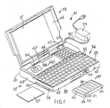
- Figure 1 is a perspective view of a self-powered portable computer embodying the invention, in an open configuration;
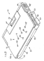
- Figure 2 is a perspective view of the computer of Fig. 1 in a closed configuration and to a different scale;
- Figure 3 is a block diagram of the computer in Fig. 1;
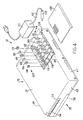
- Figure 4 is a partially exploded perspective view of the computer of Figure 2;
- Figure 5 is a partial perspective view of certain details of the computer of Fig. 1, to a different scale;
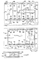
- Figure 6 is a partial plan view of the detail in Fig. 4, to a different scale;
- Figure 7 is the same view as in Fig. 6, in a first working configuration;
- Figure 8 is the same view as in Fig. 6, in a second working configuration;
- Figure 9 is a plan view in partial cross section of a detail of Figure 8;
- Figure 10 is a perspective view of the detail of Fig. 9;
- Figure 11 is a partial front cross section of Fig. 7; and
- Figure 12 is a partial front cross section of Fig. 8.
- With reference to Figures 1, 2, and 3, the self-powered portable computer, indicated as a shown by the
reference 31, comprises abase unit 32, alid 33 which is hinged onto thebase unit 32 and can be positioned between a closed configuration and an open configuration, anelectronic unit 34 housed inside thebase unit 32, akeyboard 36 for controlling theelectronic unit 34 and adisplay screen 37 carried by thelid 33. - The
base unit 32 has a substantially parallelepipedal, somewhat flattened, shape and has anupper surface 38 which is horizontal in use, abottom 39, afront part 40, arear part 41, aright side 42 and aleft side 43. Thelid 33 has afront surrface 44 and thescreen 37 is of the flat type and covers most of thefront surface 44. Thelid 33, in its closed configuration, superimposes thesurface 44 over theupper surface 38 of thebase unit 32. In its open configuration, thelid 33 is substantially vertical, allowing access to thekeyboard 36 and enabling thedisplay screen 37 to be seen. - A
mode indicator 46, for displaying characters and symbols indicating various operational states of thecomputer 31, is carried in thebase unit 32. With regard to thelid 33, it comprises aviewing zone 47 in its lower part, external to thescreen 37, so that themode indicator 46 is still visible when the lid is in its closed configuration.Cables 45 in turn correct theelectronic unit 34 inside theunit 32 to thescreen 37, through a hinging zone betweenbase unit 32 and thelid 33. - The
computer 31 is very compact, of the palm held type, having base dimensions equivalent to those of a notebook of standard A5 format, i.e. approximately 210 x 148 mm and a thickness of approximately 32mm in the closed configuration. Thescreen 37 is a 7'' screen of the reflecting liquid crystal type, equivalent to an active area of approximately 141 x 106mm and a graphics resolution of 640 x 400 dots. Themode indicator 46 has an active area of approximately 40 x 8.5 mm, enabling five graphic symbols and six alphanumeric characters to be displayed. - On its
left side 43, thecomputer 31 comprises aslot 54 with aconnector 56 for data and program exchange using a microprocessor (IC)card 57, for example of the PCMCIA 1.0/JEID4 4.0 type, conforming to standards. On itsright side 42 also, thecomputer 31 comprises aparallel connector 58 and a series connector 59 (RS-232 type) for data exchange via external lines, with external peripherals or sources such as modems, display devices, printers and memory units. Theconnectors small lid 60. - The
electronic unit 34 comprises a central processing unit (CPU) 61, a main dynamic type memory (DRAM) 62, static type memories (SRAM) 63 and 64, read only memory (ROM) 66 and a programmable read only memory (PROM) 67. Theunit 34 fruther comprisescontrol circuits screen 37 and for the data input/output lines respectively and a control andtiming unit 71 for thememories control circits CPU 61. - The
CPU 61 for example consists of an NEC V300HL microprocessor, operating at 16 MHz. TheDRAM 62 has a memory of one MByte and theSRAMs screen 37 and to the external lines and have a capacity of 32 and 128 kBytes respectively. Thecontrol circuit 68 is for example of the 82C426 type and thecontrol circuit 69 is of the PCB7310 type. The DOS progams are permanently recorded on theROM 66, whereas the BIOS programs are permanently on thePROM 67. - The
computer 31 also comprises anon-volatile bulk memory 83, for exchanging data with theelectronic unit 34. This unit comprises for example a hard disk unit (HDU) 84, securely fitted inside thebase unit 32. Somekeys 35 on thekeyboard 36 are preset to accessbulk memory 83, and themode indicator 46 has a bulk memory symbol which can be displayed to indicate that the bulk memory has been activated by theelectronic unit 34. - A
battery pack 87 comprisingbatteries 88 can be housed in theunit 32 and is capable of powering theelectronic unit 34 via a powersupply control circuit 89 in order to power the various functions of thecomputer 31. Thecontrol circuit 89 comprises a DC/DC converter 91 and arecharging control circuit 92 which is connected to themicroprocessor 61 and defines reduced power and limited operational states of thecomputer 31 so as to limit energy consumption from thebatteries 88 when some of the potential functions of thecomputer 31 are not being exploited. Thecharging control circuit 92 is connected to amain switch 94 which projects fromupper surface 38 of thebase unit 32 and can be actuated when thelid 33 is in its open configuration, in order to preset theelectronic unit 34 for operational modes associated with the closed configuration of thelid 33. Thebatteries 88 are rechargeable and thecomputer 31 can be connected to anexternal power unit 93 so as to operate on an external power supply. - The
control circuit 92 also transmits signals to themode indictor 46 so that it may display alphanumeric characters to represent the limited operational states preset by thecircuit 92. A graphic symbol representing a battery can further be activated by thecircuit 92 on theindicator 46 to display that there is an insufficient charge in the power supply. - The
lid 33 has asurface 96, on the opposite side from thesurface 44, which is accesible from the outside when thelid 33 is in the closed configuration. Thesurface 96 carries sixpresetting keys 97 which are connected to theelectronic unit 34 via thecables 45 and can be actuated by an operator in order to preset some of the operational states ofcomputer 31, when thelid 33 is in the closed configuration. - The
computer 31 also comprises a voice input/output unit 101, selection means 102 for selecting a voice-command state of the abovementioned computer for processing vocal commands, and presetting means comprising thepresetting keys 97 to preset the different operational conditions of theelectronic unit 34 in the voice-command state. Theelectronic unit 34 in turn comprises aconversion unit 107 to sample the analog signals coming from amicrophone 103 in the voice input/output unit 101 in reply to the vocal commands received and convert them into digital signals which can be processed by other circuits in thesame unit 34. Theconversion unit 107 is also able to convert digital signals coming from other circuits in theelectronic unit 34 into analog signals to be reproduced, as sounds, by a speaker 104 in theunit 101. The vocal commands, in the digital form as processed by the unit 104, are in turn stored in memory by theHDU unit 84, or by theIC card 57. - The
presetting keys 97 comprise aPLAY key 116 to playback vocal commands, anFF key 117 to fast forward the point of play-back in the memory, aSTOP key 113 to put thecomputer 31 into a state of rest, anRW key 111 to fast rewind the point of the play-back, aREC key 114 to record a vocal command from that point in the memory and aPAUSE key 112 to stop recording or play-back, in a way similar to the way in which a magnetic tape recorder/player is operated. - The
batteries 88 in the battery pack 87 (Figures 3, 4, 5, 6, 7, 8, 9, 11 and 12) are located and enclosed in acase 151 which can be housed in ahousing 152 in thebase unit 32. Thebattery pack 87 comprises twoterminals power supply conductors supply control circuit 89 and theelectronic unit 34, via two input terminals. Asocket 158 connected to externalpower supply conductors 166 and 167 can be connected, via aconventional jack plug 159 and acable 161, to theexternal power unit 93 in order to power the powersupply control circuit 89. Theconductors electronic unit 34. - The charging
control circuit 92 also comprises arecharging circuit 160 which can generate the recharging current for thebatteries 88 when thecontrol circuit 92 is powered externally. Asensor device 162 can detect the presence of thecase 151 in thehousing 152, so as to make thecircuit 160 recharging current available to therechargeable batteries 88, through theconductors - The
housing 152 can also house a series of single,
non-rechargeable, AA-size batteries 163, as an alternative to thecase 151. Intermediate conductors, indicated as a whole by thereference 164, are located in thehousing 152 and are suitably connected together so as to connect thenon-rechargeable batteries 163 in series. Thepower supply conductors last batteries 163 in order to power the powersupply control circuit 89 in the absence of thecase 151. Thesensor device 162, on the other hand, cannot detect the presence of thesingle batteries 163 and prevents hazardous attempts at recharging thenon-rechargeable batteries 163. - The
external power unit 93 and thebatteries input terminal 165 of the DC/DC conveter 91 and across thepower supply conductors 166 and 156. Thesensor device 162 controls amicroswitch 170 which is connected between the chargingcontrol circuit 92generator 160 and thepower supply conductor 156, which in turn is connected to therechargeable batteries 88. Thedevice 162 in particular consists of a lever for controlling themicroswitch 170, which lever can interact with ashoulder 171 on thecase 151 so as to be closed when thecase 151 is housed in thehousing 152. When thepower unit 93 is connected to the mains, it can recharge the set ofbatteries 88 via therecharging control circuit 92, through itscurrent generator 160 and themicroswitch 170. - The
case 151 consists of a plastic body which is parallelepipedal in shape and hollow in order to house therechargeable batteries 88. Thebatteries 88 are cylinder NiCd batteries, substantially AA-size, and have a positive pole formed by a projecting cap and a negative pole formed by a metal base. There are sixbatteries 88 housed in thecase 151, side by side and in such a way that the positive pole of one battery is next to the negative pole of another battery. The sixbatteries 88 are connected together in series by five thinconductive strips 172, each of which is soldered between the projecting cap of one battery and the base of the adjacent battery, in a manner known per se. - The
terminal 153 of thebattery pack 87 consists of the projecting cap of thefirst battery 88 positioned at one end of thecase 151 and the terminal 154 consists of the base of thelast battery 88 positioned at the other end of thecase 151. The twoterminals battery pack 87 and thecase 151 comprisesgrooves 173 in which theconductive strips 172 which connect therechargeable batteries 88 in series are housed. Two throughholes terminals single springs power supply conductors first battery 88 and the base of thelast battery 88 respectively. - The
housing 152 of thebase unit 32 is of rectangular cross section and is delimited by therear wall 41, by aninner wall 178 which is parallel to thewall 41 and by a bottom 175. Aslit 177 has been made in thewall 178, in front of the control lever of themicroswitch 170. Theshoulder 171 on thecase 161 expediently consists of apeg 155 which has a rectangular cross section and projects from the same face as the throughholes slit 177 in thewall 178 and actuate themicroswitch 170. - The
intermediate conductors 164 comprise threestrip contacts 181 and foursprings strip contacts 181 are identical, each consisting of a metal strip having two small projectingplates 187 and are positioned insuitable grooves 188 in therear wall 41. Thegrooves 188 are spaced apart from each other and the plates 18 project towards the inside of thehousing 152. The twosingle springs suitable grooves inner wall 178. - The four springs 182, 183, 184 and 186 are electrically connected in pairs so as to make up two pairs of springs, each pair positioned in a
groove inner wall 178. - Furthermore, the
springs batteries 163. Thegrooves inner wall 178 and between thegrooves single springs - The single springs 179 and 180, the
double springs housing 152 and, together with theplates 187 of thestrips 181, connect thenon-rechargeable batteries 163 in series in a manner known per se. The double springs 182, 183 and 184, 186 and thestrip contacts 181 are inserted into thecorresponding grooves housing 152. Whereas thesingle springs power supply conductors corresponding grooves openings bottom 175 of thehousing 152. - When the
case 151 is positioned in thehousing 152, the tensional force of thedouble springs plates 187 in a stable position. Thecase 151 isolates thebatteries 88 and is integral with itsrechargeable batteries 88; contact with thesingle spring 179 is solely via thecap terminal 153 and contact between thebase terminal 154 and the othersingle spring 180 is via thehole 176. Thehousing 152 is usually closed by aconventional lid 198 which is removable. - Five
ribs 194 on thebottom 175 of thehousing 152 and fiveribs 195 on thelid 198 facilitate alignment of thenon-rechargeable batteries 163 and can also hold thebattery pack 87 in position. A piece oftape 199 having a free end and an end fixed to the bottom 175, further facilitates removal of thebatteries 163 or thepack 87, in a manner known per se. - The
battery pack 87 has a nominal voltage of approximately 7.2 volts, whereas the series ofnon-rechargeable batteries 163 has a nominal voltage of approximately 9 volts. Theexternal power unit 93 is of the standard type for use with 110 to 240-volt mains voltage and can supply a d.c. nominal output voltage of 12 volts. The powersupply control circuit 89 is in turn able to operate correctly using the three different power supply sources: thebattery pack 87,individual batteries 163 and theexternal power unit 93. - When the
power unit 93 is connected to thesocket 158 and is operational, the output prevails over that of thebattery pack 87 or over that of the sixbatteries 163 optionally inserted in thehousing 152, and thecircuit 89 will be powered solely by the power supplied by theexternal power unit 93. Thediode 169 prevents thepower unit 93 from directly supplying current to thebattery pack 87 or to thebatteries 163, without any control being exerted by the rechargingcontrol circuit 92. In turn, thediode 168 prevents thebattery pack 87 or thebatteries 163 from supplying current to theexternal power unit 93 if, for example, it is not in use or it is broken. - The
portable computer 31 described above can therefore be used in self-powered mode, with the set ofrechargeable batteries 88 in thebattery pack 87, with thebatteries 163, or it can be powered externally from theexternal power unit 93 which can simultaneously recharge therechargeable batteries 88. - If the
portable computer 31 is to be powered using thebattery pack 87, the following method of operation should be adopted. Thelid 198 is removed and with one hand thecase 151 is positioned keeping it slightly at an angle with theshoulder 171 in theslit 177. Thepeg 155 is inserted into theslit 177 and thecase 151 is simultaneously lowered, so that it comes to be housed in thehousing 152. Thecap terminal 153 comes into contact with thesingle spring 179 and the othersingle spring 180, via thehole 176, comes into contact with thebase terminal 154.
Simultaneously, theshoulder 171 acts on the control lever which constitutes thesensor device 162 and closes themicroswitch 170. Thecase 151 is postioned in thehousing 152 between thedouble springs plates 187, and is held in place by the tensional force of thedouble springs housing 152 is closed by means of thelid 198, and theportable computer 31, powered from the current of therechargeable batteries 88 via thediode 169 to theconverter 91, is operational. - If the
portable computer 31 is to be used with the power supply of theexternal power unit 93, all that needs to be done is to insert thejack plug 159 into thesocket 158. Thepower unit 93 conveys the current via thediode 168 to theconverter 91 and simultaneously conveys the current to therecharging control circuit 92. If thecase 151 is housed in thehousing 152, therecharging circuit 160 will also recharge therechargeable batteries 88 via themicroswitch 162. - In the event that the batteries in the
battery pack 87 have run down, and theportable computer 31 is to be used with the power supply of thenon-rechargeable batteries 163, the following method of operation should be adopted. Thelid 198 is removed and thetape 199 is pulled so as to disengage thecase 151 from thehousing 152, lifting it out. In addition, thepeg 155 is pulled out of theslit 177 which results in themicroswitch 170 being opened. Thenon-rechargeable batteries 163 are individually positioned inside thehousing 152 between theplates 187 and thesprings housing 152 is closed by means of thelid 198 and thecomputer 31 is once again ready for use. Themicroswitch 170 stays open, interrupting the circuit connecting thebatteries 163 to thegenerator 160. If theportable computer 31 is to be powered with theexternal power unit 93, thejack plug 159 need merely be inserted into thesocket 158. Thecomputer 31 will operate on the external power supply, via thediode 168, without thebatteries 163 being damaged by the recharging current. - As is clear from the above description, it is very simple to power the
portable computer 31 and it is possible to transfer from one power supply to another quickly and easily. - The hard disk unit (HDU) 84 is adjacent to the
battery housing 152 of thebase unit 32. Theunit 84 is of a thin profile type for disks of 2,5''. A portion of theside 42 of thebase unit 32 projects upwardly with respect to thekeyboard plane 36 and the speaker 104 is lodged between thebattery housing 152 and the projecting portion of theside 42 for a space optimization of thebase unit 32. - It is understood that the
portable computer 31, thecase 151 with the set ofrechargeable batteries 88, thehousing 152, theintermediate conductors 164, theconductive strips 172 and theexternal power unit 93 may undergo various changes and improvements, with respect ot both shape and arrangements of the vaious parts, without departing from the scope of the present model.
Claims (17)
- A self-powered portable computer comprising a base unit (32), an electronic unit (34) contained within the base unit and having a plurality of electronic components, and two power supply conductors (156, 157) for the electronic unit, in which the base unit comprises a housing able to house a battery pack (87) having two terminals which can be connected to the two power supply conductors (156, 157) in order to power the electronic unit (34) and in which the battery pack comprises a case containing rechargeable batteries (88), characterised by a power supply control circuit (89) connected to the power supply conductors in order to power the components with suitable voltages and comprising a recharging circuit (160) to generate a given recharging current;
a power socket (158) which can be connected to a power unit outside the base unit in order to power the said control circuit (89) and to activate the said recharging circuit (160); and by
a sensor device (170) which can detect the presence of the battery pack (87) in the said housing (152), so as to make the recharging current of the power supply control circuit (40) available to the rechargeable batteries (58);
in which the said housing (152) can house a plurality of single non-rechargeable batteries (163) as an alternative to the said battery pack (87); and
in which the sensor device (170) does not detect the presence of single batteries in the said housing, in order that attempts at recharging the non-rechargeable batteries (63) are prevented. - A self powered portable computer according to claim 1, characterised in that the recharging circuit (160) is connected to the power supply conductors (156, 157) via a switching element which is controlled by the abovementioned sensor device.
- A portable computer according to claim 2, characterised in that the said switching element comprises a microswitch (170), and the sensor device comprises a lever for controlling the microswitch, which lever can interact with a shoulder (171) on the battery pack (87) so as to close the microswitch when the battery pack is housed in the housing.
- A portable computer according to claim 3, characterised in that the external power unit recharges the rechargeable batteries (88) contained in the pack via the recharging circuit (160) and the microswitch (170).
- A portable computer according to any preceding claim, characterised in that the housing (182) is delimited by a wall in which a slit (177) is made, wherein the control lever is aligned with the said slit and can engage with a peg (155) projecting from the battery pack, through the slit.
- A portable computer according to any preceding claim, characterised in that the housing carries intermediate conductors (164) such as to suitably connect together non-rechargeable batteries.
- A portable computer according to claim 6, characterised in that the housing is delimited by a rear wall (41), the intermediate conductors comprise strip contacts (181) each consisting of a metal strip having two small projecting plates (187), of two single springs (179, 180) and of springs (182, 183) connected together in pairs, the strips are positioned in suitable grooves (188) which are spaced apart from each other in the said wall, with the plates facing towards the inside of the housing, the two single springs (179, 180) are positioned in suitable grooves (189, 191) at each end of an inner wall (178) and are connected to the power supply conductors (156, 157), the springs connected together in pairs are postioned in suitable grooves (192, 193) which are spaced apart in the inner wall and between the two single springs, and wherein the springs all project towards the inside of the housing (132) so that, together with the strips, they connect the non-rechargeable batteries in series.
- A battery pack for a portable computer according to any preceding claim, characterised in that the case (151) comprises a hollow body which houses the rechargeable batteries (88), in which intermediate conductors (173) are provided in the hollow body in order to connect the rechargeable batteries in series between the two terminals.
- A battery pack according to claim 8, characterised in that the case is parallellepipedal in shape, the two terminals are arranged on one face of the case and the case comprises a shoulder (171) which projects from the same face as the two terminals
- A battery pack in accordance with claims 7 and 9, characterised in that the case is made of plastic and only the two terminals can come into electrical contact with the two single springs, each with a respective spring, when the case is positioned in the housing.
- A battery pack comprising a case (151) containing rechargeable batteries (88) and with two terminals (153, 134) connected to the said batteries, in which the battery pack can be positioned in a housing (152) of a portable computer of the type comprising a base unit (32) including the housing, an electronic unit (34) with a plurality of components and two power supply conductors (156, 157) for the electronic unit, characterised in that the case can be used in a computer which can be powered by an external power unit and which comprises a microswitch (170) which can detect the presence of the battery pack in the housing so as to make a recharging current supplied by the external power unit available to the rechargeable batteries;
the said case comprising a hollow parallelepipedal-shaped body, in which the rechargeable batteries (88) are housed and which carries intermediate conductors (173) in order to connect the rechargeable batteries in series; and wherein
the hollow body comprises a shoulder (155) which can interact with the microswitch (170) so as to receive the recharging current when the case is housed in the said housing. - A battery pack according to claim 11, characterised in that the said shoulder (155) is defined by a peg (155) which projects from the case (151), which peg is able to pass through a slit (177) in a wall of the housing (152) in order to close the microswitch (170) when the hollow body is inserted into the housing.
- A battery pack according to claim 11 or 12, characterised in that it can be used in a computer having a housing (152) which comprises intermediate conductors (181) such as to connect in series non-rechargeable batteries which can be mounted in the said housing as an alternative to the battery pack, in which the rechargeable (88) batteries in the battery pack are connected in series inside the case, and in which the case isolates the rechargeable batteries from the intermediate conductors in the housing.
- A self powered portable computer comprising a base unit including a housing to receive a rechargeable battery pack or a plurality of non-rechargeable batteries and including means for connecting the computer to an external power source characterised by a sensor device responsive to the presence of the battery pack to supply a recharging current to the battery pack from a recharging circuit when the computer is connected to the external power source.
- A portable computer comprising a base unit (32), an electronic unit (34) contained within the base unit and wherein the base unit comprises a battery housing (152) able to house a battery pack (87) for powering the electronic unit, characterised by a hard disk unit (HDU) (84) operatively connected with said electronic unit, wherein the base unit has base dimensions substantially equivalent to an A5 format (210 x 148 mm) and wherein said disk unit (84) is adjacent to said battery housing (152).
- A portable computer according to claim 15, comprising a keyboard (36) for controlling the electronic unit (34), characterised by a voice input/output unit (101) selectable for processing verbal annotations, said unit having a speaker (104) for reproducing said verbal annotations, wherein the verbal annotations can be stored in said hard disk unit, wherein said base unit (32) comprises a side wall (42) having a portion projecting upwardly with respect to a keyboard plane and wherein said speaker (104) is lodged in said base unit at the side wall (42) having said projecting portion.
- A portable computer according to claim 16, further comprising a lid (33) hinged on said base unit (32) and which can be superimposed to the keyboard (36) in its closed configuration, characterised in that said projecting portion of the side wall (42) is able to accomodate an edge of said lid (33) in its closed configuration.
Applications Claiming Priority (2)
| Application Number | Priority Date | Filing Date | Title |
|---|---|---|---|
| IT92TO000062U IT227496Y1 (en) | 1992-03-12 | 1992-03-12 | "SELF-POWERED PORTABLE CALCULATOR" |
| ITTO920062U | 1992-03-12 |
Publications (3)
| Publication Number | Publication Date |
|---|---|
| EP0562723A2 true EP0562723A2 (en) | 1993-09-29 |
| EP0562723A3 EP0562723A3 (en) | 1993-12-29 |
| EP0562723B1 EP0562723B1 (en) | 2001-11-14 |
Family
ID=11409960
Family Applications (1)
| Application Number | Title | Priority Date | Filing Date |
|---|---|---|---|
| EP93301488A Expired - Lifetime EP0562723B1 (en) | 1992-03-12 | 1993-02-26 | Self powered portable computer |
Country Status (5)
| Country | Link |
|---|---|
| US (1) | US5475626A (en) |
| EP (1) | EP0562723B1 (en) |
| JP (1) | JPH0643966A (en) |
| DE (1) | DE69331117T2 (en) |
| IT (1) | IT227496Y1 (en) |
Cited By (2)
| Publication number | Priority date | Publication date | Assignee | Title |
|---|---|---|---|---|
| US6404623B1 (en) | 1999-10-19 | 2002-06-11 | Fujitsu Limited | Portable electronic apparatus |
| WO2006071330A1 (en) * | 2004-12-29 | 2006-07-06 | Intel Corporation | A universal battery pack |
Families Citing this family (34)
| Publication number | Priority date | Publication date | Assignee | Title |
|---|---|---|---|---|
| US5583744A (en) | 1994-09-06 | 1996-12-10 | Citizen Watch Co., Ltd. | Portable computer with detachable battery pack |
| JP3025416U (en) | 1994-12-06 | 1996-06-21 | ディジタル イクイプメント コーポレイション | 1 inch high notebook computer |
| US5673173A (en) * | 1995-03-01 | 1997-09-30 | Acer Incorporated | Portable computer having a modular power conversion unit |
| US5860015A (en) * | 1995-12-14 | 1999-01-12 | Gateway 2000, Inc. | Detachable palm rest with backup battery |
| US5739666A (en) * | 1996-06-03 | 1998-04-14 | Nierescher; David S. | Rechargeable battery pack for battery powered devices |
| US5867008A (en) * | 1996-06-05 | 1999-02-02 | Double-Time Battery Corporation | Overcharge protection circuitry for rechargeable battery pack |
| JP3294512B2 (en) * | 1996-09-10 | 2002-06-24 | キヤノン株式会社 | Electronic equipment and power supply processing method thereof |
| US5862392A (en) * | 1996-09-27 | 1999-01-19 | Energy Research Corporation | Battery incorporated into computer carrying case |
| US5918186A (en) * | 1996-10-15 | 1999-06-29 | Ericsson Inc. | Rechargeable battery enabling reduction of battery overheating probability during charging |
| US6634896B1 (en) * | 1997-06-27 | 2003-10-21 | Patrick Potega | Method and apparatus for transferring electrical signals among electrical devices |
| US6972945B1 (en) * | 1997-10-17 | 2005-12-06 | Gateway Inc. | Modular computer device and computer keyboard for modular device |
| JP3733239B2 (en) * | 1998-04-15 | 2006-01-11 | キヤノン株式会社 | Recording device |
| KR100521347B1 (en) | 1998-11-30 | 2006-01-12 | 삼성전자주식회사 | A portable computer having a system control function when detaching a battery pack from the portable computer |
| KR100536583B1 (en) * | 1998-12-01 | 2006-02-28 | 삼성전자주식회사 | Ac/dc adaptor sensing load and portable electronics apparatus for use with the same |
| US6262886B1 (en) * | 1999-09-30 | 2001-07-17 | Apple Computer, Inc. | Translucent protective covering for a computer housing |
| JP2001337812A (en) * | 2000-03-23 | 2001-12-07 | Fujitsu Ltd | Status display control device, electronic device, and storage medium |
| JP2002297259A (en) * | 2001-03-30 | 2002-10-11 | Fujitsu Ltd | Electronic equipment |
| US6532149B2 (en) * | 2001-05-22 | 2003-03-11 | Vasant Dhar | Portable computer having secondary display |
| JP4366885B2 (en) * | 2001-05-24 | 2009-11-18 | 日本電気株式会社 | Optical communication network, optical communication node device, and fault location specifying method used therefor |
| JP3593092B2 (en) * | 2001-11-30 | 2004-11-24 | 株式会社東芝 | Information processing equipment |
| US20040257034A1 (en) * | 2003-06-23 | 2004-12-23 | Logitech Europe S.A. | Rechargeable battery pack and housing |
| US20050008186A1 (en) * | 2003-07-08 | 2005-01-13 | Dell Products L.P. | Sealing composition for inflated articles |
| US8711732B2 (en) * | 2004-05-27 | 2014-04-29 | Richard G. Johnson | Synthesized interoperable communications |
| US20070088553A1 (en) * | 2004-05-27 | 2007-04-19 | Johnson Richard G | Synthesized interoperable communications |
| US7466125B2 (en) * | 2004-07-12 | 2008-12-16 | Feig Electronic Gmbh | Position transmitter and method for determining a position of a rotating shaft |
| JP4991122B2 (en) * | 2005-04-18 | 2012-08-01 | 株式会社東芝 | Electronics |
| US7040932B1 (en) * | 2005-06-14 | 2006-05-09 | Orrin Edward Klitzner | Collapsible plug |
| WO2008024095A2 (en) * | 2005-07-13 | 2008-02-28 | Johnson Richard G | Anti-terrorism interoperable radio communications |
| WO2009003083A1 (en) | 2007-06-26 | 2008-12-31 | The Coleman Company, Inc. | Electrical appliance that utilizes multiple power sources |
| DE102007051600B3 (en) * | 2007-10-29 | 2009-06-18 | Fujitsu Siemens Computers Gmbh | Portable computer system, has battery module with rechargeable battery or connection module with power line inserted in shaft, where battery is charged by electrical connection or main voltage is supplied to power pack of extension module |
| US20100283270A1 (en) * | 2009-05-07 | 2010-11-11 | Dell Products L.P. | Magnetic Latch and Method for Manufacture Thereof |
| US8173893B2 (en) * | 2010-05-28 | 2012-05-08 | Yao-Hung Huang | Electronic device case |
| JP5516547B2 (en) * | 2011-10-28 | 2014-06-11 | 株式会社デンソー | Electronic control unit |
| JP2013157291A (en) * | 2012-01-31 | 2013-08-15 | Toshiba Corp | Structure including battery unit, and electronic apparatus |
Family Cites Families (13)
| Publication number | Priority date | Publication date | Assignee | Title |
|---|---|---|---|---|
| US4776016A (en) * | 1985-11-21 | 1988-10-04 | Position Orientation Systems, Inc. | Voice control system |
| US4769764A (en) * | 1986-08-11 | 1988-09-06 | Isaac Levanon | Modular computer system with portable travel unit |
| US5191617A (en) * | 1987-04-20 | 1993-03-02 | Intechnica International, Inc. | Voice interactive computer system |
| US5030128A (en) * | 1989-03-06 | 1991-07-09 | Dynabook Technologies Corporation | Docking module |
| US5015546A (en) * | 1989-06-12 | 1991-05-14 | Grid Systems Corporation | Battery compartment |
| US5239495A (en) * | 1989-06-23 | 1993-08-24 | Kabushiki Kaisha Toshiba | Power supply control system for a portable computer |
| US5289339A (en) * | 1989-06-28 | 1994-02-22 | Kabushiki Kaisha Toshiba | Portable electronic device with memory card unit having symmetrical terminals |
| EP0435317A3 (en) * | 1989-12-28 | 1992-06-17 | Kabushiki Kaisha Toshiba | Personal computer for performing charge and switching control of different types of battery packs |
| US5200913A (en) * | 1990-05-04 | 1993-04-06 | Grid Systems, Inc. | Combination laptop and pad computer |
| US5251105A (en) * | 1990-06-25 | 1993-10-05 | Kabushiki Kaisha Toshiba | Portable electronic apparatus having a battery pack with a mechanism for latching and an independent mechanism for temporarily preventing detachment |
| JPH0462896A (en) * | 1990-06-25 | 1992-02-27 | Toshiba Corp | Compact electronic device |
| US5175672A (en) * | 1990-08-09 | 1992-12-29 | Outbound Systems, Inc. | Housing apparatus for portable computer systems |
| GB2258326B (en) * | 1991-10-01 | 1995-09-20 | Hsi Kuang Ma | Notebook computer |
-
1992
- 1992-03-12 IT IT92TO000062U patent/IT227496Y1/en active IP Right Grant
-
1993
- 1993-02-25 US US08/022,495 patent/US5475626A/en not_active Expired - Lifetime
- 1993-02-26 DE DE69331117T patent/DE69331117T2/en not_active Expired - Lifetime
- 1993-02-26 EP EP93301488A patent/EP0562723B1/en not_active Expired - Lifetime
- 1993-03-12 JP JP5051849A patent/JPH0643966A/en active Pending
Cited By (4)
| Publication number | Priority date | Publication date | Assignee | Title |
|---|---|---|---|---|
| US6404623B1 (en) | 1999-10-19 | 2002-06-11 | Fujitsu Limited | Portable electronic apparatus |
| WO2006071330A1 (en) * | 2004-12-29 | 2006-07-06 | Intel Corporation | A universal battery pack |
| US7280347B2 (en) | 2004-12-29 | 2007-10-09 | Intel Corporation | Universal battery pack |
| CN101095248B (en) * | 2004-12-29 | 2010-05-26 | 英特尔公司 | Universal battery pack |
Also Published As
| Publication number | Publication date |
|---|---|
| JPH0643966A (en) | 1994-02-18 |
| DE69331117T2 (en) | 2002-07-18 |
| ITTO920062U1 (en) | 1993-09-12 |
| US5475626A (en) | 1995-12-12 |
| IT227496Y1 (en) | 1997-12-15 |
| EP0562723A3 (en) | 1993-12-29 |
| DE69331117D1 (en) | 2001-12-20 |
| ITTO920062V0 (en) | 1992-03-12 |
| EP0562723B1 (en) | 2001-11-14 |
Similar Documents
| Publication | Publication Date | Title |
|---|---|---|
| US5475626A (en) | Portable computer with a simple power supply control of chargeable and non-rechargeable battery packs | |
| US4497036A (en) | Portable computer | |
| CN100375322C (en) | Battery Identification Method | |
| EP0564092B1 (en) | Portable computer with mode indicator | |
| EP0987620B1 (en) | Function extending apparatus, electronic apparatus and electronic system | |
| US5563005A (en) | Battery pack having protected terminals and connection mechanism | |
| EP0689127B1 (en) | Recording and/or reproducing system and data backup system | |
| JP2000333377A (en) | Entertainment and charging systems | |
| US20070022232A1 (en) | Cellular telephone with integrated usb port engagement device that provides access to multimedia card as a solid-state device | |
| US6078164A (en) | Portable electronic appliance | |
| WO1998001917A3 (en) | Accumulator and charging set for an accumulator | |
| JP2523960B2 (en) | Document editing device | |
| CA2090582C (en) | Portable computer | |
| US6403254B1 (en) | Battery means for hand held electronic devices | |
| KR20010089396A (en) | Entertainment device and external storage device for entertainment device | |
| JPH04285879A (en) | Small-sized electronic machinery | |
| US4754429A (en) | Cassette type magnetic bubble memory | |
| JPH0227501Y2 (en) | ||
| JPH0495115A (en) | Information processor and battery used for the same | |
| AU731475B3 (en) | Mobile phone battery pack with recording device for memorizing recharged number of times | |
| JPH05313787A (en) | Small-size electronic equipment | |
| JPS63231563A (en) | Electronics | |
| JPH0510730B2 (en) | ||
| JPH06233467A (en) | Power supply for electronic apparatus | |
| JP2004241331A (en) | Connection device |
Legal Events
| Date | Code | Title | Description |
|---|---|---|---|
| PUAI | Public reference made under article 153(3) epc to a published international application that has entered the european phase |
Free format text: ORIGINAL CODE: 0009012 |
|
| AK | Designated contracting states |
Kind code of ref document: A2 Designated state(s): DE FR GB |
|
| PUAL | Search report despatched |
Free format text: ORIGINAL CODE: 0009013 |
|
| AK | Designated contracting states |
Kind code of ref document: A3 Designated state(s): DE FR GB |
|
| 17P | Request for examination filed |
Effective date: 19940525 |
|
| 17Q | First examination report despatched |
Effective date: 19991019 |
|
| GRAG | Despatch of communication of intention to grant |
Free format text: ORIGINAL CODE: EPIDOS AGRA |
|
| GRAG | Despatch of communication of intention to grant |
Free format text: ORIGINAL CODE: EPIDOS AGRA |
|
| GRAH | Despatch of communication of intention to grant a patent |
Free format text: ORIGINAL CODE: EPIDOS IGRA |
|
| GRAH | Despatch of communication of intention to grant a patent |
Free format text: ORIGINAL CODE: EPIDOS IGRA |
|
| GRAA | (expected) grant |
Free format text: ORIGINAL CODE: 0009210 |
|
| AK | Designated contracting states |
Kind code of ref document: B1 Designated state(s): DE FR GB |
|
| REF | Corresponds to: |
Ref document number: 69331117 Country of ref document: DE Date of ref document: 20011220 |
|
| REG | Reference to a national code |
Ref country code: GB Ref legal event code: IF02 |
|
| ET | Fr: translation filed | ||
| PLBE | No opposition filed within time limit |
Free format text: ORIGINAL CODE: 0009261 |
|
| STAA | Information on the status of an ep patent application or granted ep patent |
Free format text: STATUS: NO OPPOSITION FILED WITHIN TIME LIMIT |
|
| 26N | No opposition filed | ||
| PGFP | Annual fee paid to national office [announced via postgrant information from national office to epo] |
Ref country code: FR Payment date: 20120306 Year of fee payment: 20 |
|
| PGFP | Annual fee paid to national office [announced via postgrant information from national office to epo] |
Ref country code: DE Payment date: 20120228 Year of fee payment: 20 |
|
| PGFP | Annual fee paid to national office [announced via postgrant information from national office to epo] |
Ref country code: GB Payment date: 20120224 Year of fee payment: 20 |
|
| REG | Reference to a national code |
Ref country code: DE Ref legal event code: R071 Ref document number: 69331117 Country of ref document: DE |
|
| REG | Reference to a national code |
Ref country code: GB Ref legal event code: PE20 Expiry date: 20130225 |
|
| PG25 | Lapsed in a contracting state [announced via postgrant information from national office to epo] |
Ref country code: DE Free format text: LAPSE BECAUSE OF EXPIRATION OF PROTECTION Effective date: 20130227 Ref country code: GB Free format text: LAPSE BECAUSE OF EXPIRATION OF PROTECTION Effective date: 20130225 |