EP0562399A2 - Apparatus for placing corner protectors onto palletized loads - Google Patents
Apparatus for placing corner protectors onto palletized loads Download PDFInfo
- Publication number
- EP0562399A2 EP0562399A2 EP93104134A EP93104134A EP0562399A2 EP 0562399 A2 EP0562399 A2 EP 0562399A2 EP 93104134 A EP93104134 A EP 93104134A EP 93104134 A EP93104134 A EP 93104134A EP 0562399 A2 EP0562399 A2 EP 0562399A2
- Authority
- EP
- European Patent Office
- Prior art keywords
- corner
- corner protector
- magazine
- chute
- panel
- Prior art date
- Legal status (The legal status is an assumption and is not a legal conclusion. Google has not performed a legal analysis and makes no representation as to the accuracy of the status listed.)
- Granted
Links
Images


Classifications
-
- B—PERFORMING OPERATIONS; TRANSPORTING
- B65—CONVEYING; PACKING; STORING; HANDLING THIN OR FILAMENTARY MATERIAL
- B65B—MACHINES, APPARATUS OR DEVICES FOR, OR METHODS OF, PACKAGING ARTICLES OR MATERIALS; UNPACKING
- B65B13/00—Bundling articles
- B65B13/18—Details of, or auxiliary devices used in, bundling machines or bundling tools
- B65B13/181—Details of, or auxiliary devices used in, bundling machines or bundling tools applying edge protecting members during bundling
-
- Y—GENERAL TAGGING OF NEW TECHNOLOGICAL DEVELOPMENTS; GENERAL TAGGING OF CROSS-SECTIONAL TECHNOLOGIES SPANNING OVER SEVERAL SECTIONS OF THE IPC; TECHNICAL SUBJECTS COVERED BY FORMER USPC CROSS-REFERENCE ART COLLECTIONS [XRACs] AND DIGESTS
- Y10—TECHNICAL SUBJECTS COVERED BY FORMER USPC
- Y10T—TECHNICAL SUBJECTS COVERED BY FORMER US CLASSIFICATION
- Y10T29/00—Metal working
- Y10T29/53—Means to assemble or disassemble
- Y10T29/53478—Means to assemble or disassemble with magazine supply
Definitions
- This apparatus pertains to a novel apparatus for placing corner protectors onto vertical corners of palletized loads to be then wrapped or strapped.
- the apparatus accommodates palletized loads within a range of varying dimensions and minimizes manual handling of the corner protectors.
- corner protectors of a type having two elongate panels meeting generally at a right angle are placed onto the load.
- the corner protectors are placed so as to protect the vertical corners of the load against being crushed by the film or strapping.
- corner protectors made of laminated paper, are available commercially from Shippers Paper Products Company (a unit of Illinois Tool Works Ins.) of Cincinnati, Ohio, under its AN-GLEBOARD trademark.
- This invention provides a novel apparatus for placing corner protectors onto palletized loads having vertical sides meeting generally at right angles to define vertical corners. After the corner protectors have been placed onto the vertical corners by the novel apparatus, the loads are ready to be then wrapped with stretch film or strapped with steel strapping or oriented polymeric strapping.
- the apparatus comprises a magazine adapted to hold the supply of the corner protectors and mechanisms for removing one corner protector from the magazine, transferring the corner protector to a position of initial engagement, and displacing the corner protector from such position.
- the inside surface of one panel of the corner panel is disposed in close proximity to one vertical side of the load. Moreover, in such position, the inside surface of the other panel of the corner protector faces the vertical side meeting the vertical side engaged thereby.
- the corner protector is displaced from such position to such extent as may be then necessary to cause the inside surface of the other panel to engage the vertical side faced by the other panel.
- the apparatus is useful with palletized loads within a range of varying dimensions.
- the magazine is adapted to hold a supply of corner protectors extending vertically and being nested within one another.
- the magazine comprises a chute inclined forwardly and downwardly toward an outlet end.
- the chute is adapted to support the supply of nested corner protectors with their outside corners facing forwardly and to guide the corner protectors supported thereby forwardly toward the outlet end of the chute.
- the magazine comprises a mechanism for pressing against an endmost one of the corner protectors supported by the chute so as to prevent the corner protectors supported thereby from tipping backwardly.
- the pressing mechanism may comprise a wheeled carriage disposed movably within the chute.
- the wheeled carriage is adapted to move downwardly toward the corner protectors supported by the chute.
- the wheeled carriage comprises an upright member adapted to press against the endmost one of the corner protectors supported thereby.
- the magazine comprises a mechanism for elevating the corner protector nearest to the outlet end of the chute to an elevated position where the elevated corner protector is removed from the magazine.
- the apparatus comprises a mechanism engageable releasably with the outside surface of such one panel for gripping the corner protector as the corner protector is removed, transferred, and displaced.
- the gripping mechanism may comprise a pair of vacuum cups engageable releasably with the outside surface of such one panel of the corner protector at vertically spaced locations.
- a load 10 resting on a pallet 12 is being wrapped with a band 14 of stretch film by a wrapping machine 16, after corner protectors 18 have been applied to vertical corners of the load 10 by four similar apparatus 20, each constituting a first embodiment of this invention.
- the palletized load 10 which may comprise stacked cartons (not shown) or other items, conforms generally to a rectangular solid.
- the load 10 has two pairs of opposed, vertical sides 22, 24, which meet generally at right angles to define vertical corners 26 of the load 10.
- the wrapping machine 16 which is shown fragmentarily in Figure 1, may be of a type exemplified in Salzsauler U. S. Patents No. 4,934,123, and No. 4,938,008.
- Such wrapping machines are available from ITW-Mima (a division of Illinois Tool Works Inc.) of Boca Raton, Florida, under its COBRA trademark.
- each corner protector 18 has two elongate panels 30 meeting generally at a right angle to define an outside corner 32 and an inside corner 34.
- Each elongate panel 30 has an outside surface 36 and an inside surface 38.
- Each corner protector 18 is cut to a length equal approximately to the height of the load 10 at one of the vertical corners 26. The corner protectors 18 protect the vertical corners 26 against being crushed by the band 14 of stretch film as the load 10 is wrapped by the wrapping machine 16.
- FIG 19 As shown fragmentarily in Figure 19, four such apparatus 20 are provided, two in a "right-hand” configuration and two in a "left-hand” configuration.
- the apparatus 20 at the lower left and the upper right in Figure 16 are of the "right-hand” configuration.
- the apparatus 20 at the upper left and the lower right in Figure 16 are of the "left-hand” configuration.
- the apparatus 20 comprises a magazine 40 adapted to hold a supply of the corner protectors 18 and mechanisms to be later described for removing one corner protector 18 from the magazine 40, transferring the corner protector 18 to a position of initial engagement, and transferring the corner protector 18 to a position of initial engagement, and displacing the corner protector 18 from the position of initial engagement into a position of final engagement.
- a magazine 40 adapted to hold a supply of the corner protectors 18 and mechanisms to be later described for removing one corner protector 18 from the magazine 40, transferring the corner protector 18 to a position of initial engagement, and transferring the corner protector 18 to a position of initial engagement, and displacing the corner protector 18 from the position of initial engagement into a position of final engagement.
- the inside surface 38 of one panel 30 of the corner protector 18 is disposed in close proximity to one vertical side 24 of the load 10. Moreover, in such position, the inside surface 38 of the other panel 30 of the corner protector 18 faces the vertical side 26 meeting the vertical side 24 engaged thereby.
- the corner protector 18 is displaced from the position of initial engagement into the position of final engagement, the corner protector 18 is displaced to such extent as may be then necessary to cause the inside surface 38 of the panel 30 facing such side 26 to engage such side 26, generally in surface-to-surface engagement.
- the magazine 40 comprises an elongate hopper or chute 60, which has a lower wall 62 with an elongate slot 64 and two side walls 66, and which is inclined forwardly and downwardly toward an outlet end 68.
- the chute 60 is affixed to a post 70, which is mounted on a pedestal 72, and which is counterbalanced by a horizontal beam 74 extending backwardly from the post 70.
- the beam 74 has a front end 76 affixed to the post 70 and a back end 78 (see Figure 8) mounted on a pedestal 80.
- the chute 60 is supported by a beam 82 inclined similarly, affixed to the post 70, and braced by a brace 84 extending vertically between the beam 74 and the beam 84.
- the magazine 40 comprises a wheeled carriage 90 having four wheels 92 and being disposed movably within the chute 60, between the side walls 66.
- the carriage 90 has a centering guide 94 with an upper handle 96 and a lower hook 98.
- the centering guide 96 extends downwardly through the elongate slot 64 to help in centering the carriage 90 between the side walls 66 and in guiding the carriage 90 along the chute 60.
- the handle 96 is convenient for moving the carriage 90 backwardly and upwardly along the chute 60.
- the hook 98 is adapted to fit under the lower wall 62, at the upper extremity of the elongate slot 64, with a frictional fit enabling the carriage 90 to be temporarily held at such extremity while more corner protectors 18 are being added.
- the wheeled carriage 90 carries an upright member 100 having a substantial height compared to the corner protectors 18.
- An upper portion 102 of the upright member 100 is adapted to press against the inside corner 34 of the endmost one of the corner protectors 18 supported by the chute 60, so as to prevent the corner protectors 18 supported thereby from tipping backwardly, and so as to feed the corner protectors 18 forwardly along the chute 60.
- a lower portion 104 of the upright member 100 extends downwardly through the elongate slot 64 to help in centering the carriage 90 between the side walls 66 and in guiding the carriage 90 along the chute 60.
- the magazine 40 comprises an escapement 110, which is mounted to the post 70 so as to be vertically movable between a lower position and an upper position.
- a Y-shaped retainer 112 is mounted to the escapement 110 for conjoint movement with the escapement 110.
- the escapement 110 has a lower, hook-shaped portion 114, which is arranged to engage the lower end of the corner protector 18 nearest to the outlet end 68 of the chute 60 and to elevate such corner protector 18 to an elevated position (see Figure 9) where such corner protector 18 is removed from the magazine 40 in a manner to be later described.
- a blade 116 having a lower, saw-toothed edge (see Figures 8 and 11) is mounted to the post 70, above the next corner protectors 18, so as to prevent more than one corner protector 18 from being elevated at any one time.
- a double-acting, pneumatic, piston-cylinder mechanism 118 mounted operatively on the post 70 is operable to move the escapement 110 between its lower position and its upper position.
- the magazine 40 comprises a retaining mechanism 120, which is mounted operatively on a bracket 122 secured to the post 70 in an elevated position.
- the position of the bracket 122 relative to the post 70 is adjustable, within a limited range of vertical adjustment so as to accommodate corner protectors of different lengths.
- the retaining mechanism 120 comprises an arm 124 having a proximal end 126 and a distal end 128 and being mounted pivotably the bracket 122, via a pivot pin 138, so as to be pivotable between a vertical position and a horizontal position.
- the arm 124 is shown in the vertical position in full lines and in the horizontal position in dashed lines.
- a Y-shaped retainer 132 is affixed to the distal end 128 of the arm 124.
- the retaining mechanism 120 comprises a double-acting, pneumatic, piston-cylinder mechanism 134, which is mounted operatively on the bracket 122.
- the mechanism 120 is connected to the arm 124 by a link 136, which is connected to the proximal end 126 by a pivot pin 138, and is operable to pivot the arm 124 between the vertical and horizontal positions.
- the retainer 132 engages the corner protector 18 nearest to the outlet end 68 of the chute 60, so as to retain the corner protectors 18 supported by the chute 60.
- the retaining mechanism 120 is arranged to pivot the arm 124 from the vertical position into the horizontal position, but only when the escapement 110 has elevated the corner protector 18 nearest to the outlet end 68 of the chute 60 to the elevated position, so as to permit such corner protector 18 to be then gripped (before its removal from the magazine 40) in a manner to be later described.
- the escapement 110 and the retainer 112 are arranged to return to the lower position after such corner protector 18 has been gripped and before such corner protector 18 is removed from the magazine 40.
- the retaining mechanism 120 is arranged to pivot the arm 124 from the horizontal position into the vertical position after such corner protector 18 has been removed.
- the apparatus 20 comprises mechanisms 140 for removing one corner protector 18 from the magazine 40, transferring the corner protector 18 to the position of initial engagement, and displacing the corner protector 18 from the position of initial engagement to the position of final engagement.
- the corner protector 18 to be thus removed is the corner protector 18 nearest to the outlet end 68 of the magazine 40.
- the apparatus 20 is shown in Figure 15 as removing the corner protector 18 from the magazine 40.
- the apparatus 20 is shown in Figures 16, 17, and 18 in successive stages in transferring the corner protector 18 to the position of final engagement.
- Each of the apparatus 20 is shown in Figure 19 as having displaced one corner protector 18 from its position of initial engagement into its position of final engagement.
- the inside surface 38 of one panel 30 of the corner protector 18 is disposed in close proximity to one vertical side 22 of the load 10, in the position of initial engagement. Moreover, in the position of initial engagement, the inside surface 38 of the other panel 30 of the corner protector 18 faces the vertical side 24 meeting the vertical side 32 engaged thereby.
- the corner protector 18 is displaced from the position of initial engagement into the position of final engagement, the corner protector 18 is displaced to such extent as may be then necessary to cause the inside surface 38 of the side panel 30 facing such side 24 to engage such side 24, generally in surface-to-surface engagement.
- the mechanisms 140 comprise a pivotable structure 142 mounted pivotably in a manner to be later described, a rail structure 144 mounted pivotably on the pivotable structure 142, a retractable structure 146 mounted movably on the rail structure 144, and a pivotable fixture 148 mounted pivotably on the retractable structure 142.
- the pivotable structure 142 is mounted pivotably on a fixed pedestal 160, via aligned upper and lower journals 162 (upper shown) so as to be pivotably movable over a limited range of pivotal motion.
- the pivotable structure 142 is shown at one extreme of such range in Figures 15 and 16 and at the other extreme of such range in Figures 17 and 18.
- the pivotable structure 142 includes a main beam 164 mounted pivotably on the journals 162 and a cross member 166 bolted to the main beam 164 and extended at a right angle relative to the main beam 164.
- a double-acting, pneumatic, piston-cylinder mechanism 168 is arranged to pivot the pivotable structure 142 relative to the fixed pedestal 160, between the extremes of such range.
- the rail structure 144 comprises a pair of parallel rails 170 (see Figure 3) having a common base 172, which is mounted pivotably on the cross member 166 of the pivotable structure 142, via a pivot pin 174 shown in phantom lines.
- a double-acting, pneumatic, piston cylinder mechanism 178 is arranged to pivot the rail structure 144 relative to the cross plate 166, over a limited range of pivotal motion. At one extreme of such range (see Figure 15) the rail structure 144 is parallel to the cross member 166. At the other extreme thereof (see Figure 177 the rail structure 144 defines a slight angle relative to the cross member 166.
- the retractable structure 146 comprises a box beam 180, which is parallel to the rails 170 and which is mounted movably on the rails 170, via a pair of guide blocks 182 enabling the box beam 180 to move along the rails 170.
- the retractable structure 146 also comprises a supporting frame 184, which is bolted to the box beam 180, via a connecting structure 186, so as to extend at a right angle from one end of the box beam 180.
- a double-acting, pneumatic, piston-cylinder mechanism 188 is arranged to move the retractable structure 146 relative to the rail structure 144, between an advanced position and a retracted position.
- the pivotable fixture 148 is mounted pivotably to the supporting frame 184 via aligned upper and lower journals 190 (one shown) so as to be pivotable between an inwardly pivoted position wherein the pivotable fixture 148 is pivoted inwardly (see Figure 1 and Figures 16, 17, and 18) against the supporting frame 184 and an outwardly pivoted position wherein the pivotable fixture 148 is pivoted outwardly (see Figure 15) from the supporting frame 184.
- a double-acting, pneumatic, rotary motor 200 (see Figure 3) is arranged to pivot the pivotable fixture 148 relative to the supporting frame 184, between the inwardly pivoted and outwardly pivoted positions.
- the pivotable fixture 148 comprises a gripping mechanism 210, which includes two similar, vertically spaced, vacuum-actuated, releasable grippers 212.
- Each gripper 212 has a retractable vacuum cup 214 of a known type, which is extended to make initial engagement with an elongate panel 30 of the endmost one of the corner protectors 18 in the magazine 40, after the escapement 110 has lifted the endmost corner protector 18 to the elevated position.
- the vacuum cup 214 is retracted after such engagement has been made, and after partial vacuum has been drawn through the vacuum cup 214 to grip such panel 30.
- the pivotable fixture 148 includes an elongate angle 220 extending vertically and generally between the grippers 212 and defining an elongate flange 222 extending vertically.
- the pivotable fixture 148 and associated grippers 212 of the gripping mechanism 210 of one of the apparatus 20 in the "left-hand" configuration are shown fragmentarily in Figure 20.
- the pivotable fixture 148 has a recess 230, which receives the corner protector panel 30 gripped by the vacuum cups 214, when the vacuum cups 214 are retracted.
- the pivotable fixture 148 may engage one vertical side 24 of the load 10.
- such panel 30 is received by the recess 230, such panel does not engage such side 24 but is disposed in close proximity to such side 24.
- the elongate flange 222 prevents the corner protector 18 from being pulled off the vacuum cups 214 accidentally when the corner protector 18 is being displaced from the position of initial engagement to the position of final engagement.
- the mechanisms 140 are operated for removing one corner protector 18 from the magazine 40, transferring the corner protector 18 to the position of initial engagement, and displacing the corner protector 18 from the position of initial engagement to the position of final engagement.
- the mechanisms 140 are positioned to enable the pneumatic motor 200 to pivot pivotable fixture 148 from its inwardly pivoted position into its outwardly pivoted position, in which the grippers 212 are positioned to engage the outside surface 36 of one elongate panel 30 of the endmost one of the corner protectors 18 in the magazine 18, after the escapement 110 has gifted the endmost corner protector 18 to the elevated position.
- the pivotable structure 142 is positioned at one extreme of its limited range of pivotal motion.
- the rail structure 144 is positioned parallel to the cross member 166, and the retractable structure 146 is positioned in its retracted position
- the vacuum cups 214 are extended and vacuum pressure is drawn through the vacuum cups 214, which grip such panel 30 at its outside surface 96. Thereupon, as shown in Figure 16, the pivotable fixture 148 is pivoted from the outwardly pivoted position into the inwardly pivoted position with the vacuum cups 214 gripping such panel 30, and the vacuum cups 214 are retracted.
- the piston-cylinder mechanism 166 is used to pivot the pivotable structure 142 to the other extreme (see Figure 17) of its limited range of pivotal motion.
- the rail structure 144, the retractable structure 146, and the pivotable fixture 148 are pivoted with the pivotable structure 142.
- the rail structure 144 is pivoted so as to define a slight angle (see Figure 17) relative to the cross member 166 of the pivotable structure 166.
- the piston-cylinder mechanism 188 is used to move the retractable structure 146 from its retracted position into the advanced position.
- the corner protector 18 having one elongate panel 30 gripped at its outside surface 36 is moved to the position of initial engagement.
- the inside surface 38 of the panel 30 gripped thereby is disposed in close proximity to one vertical side 22 of the load 10.
- the inside surface 38 of the other panel 30 thereof faces the vertical side 24 meeting the vertical side 22 engaged thereby.
- the piston-cylinder mechanism 178 is used to pivot the rail structure 144 toward and possibly beyond its position parallel with the cross member 166, as shown in Figure 19, whereby the corner protector 18 having one elongate panel 30 gripped at its outside surface 36 is moved to the position of final engagement.
- corner protector 18 is displaced to such extent as may be then necessary to cause the inside surface 38 of the panel 30 facing the vertical side 24 of the load 10 to engage such side 24, generally in surface-to-surface engagement.
- an apparatus 20' for placing corner protectors onto palletized loads constitutes an alternative embodiment of this invention.
- the apparatus 20' is similar to the apparatus 20 and functions similarly, except that the connecting structure 186' is simpler than the connecting structure 186, that the pivotable fixture 148' is simpler than the pivotable fixture 148, that a double-acting, pneumatic, piston-cylinder mechanism 250 replaces the double-acting, pneumatic, rotary motor 200, and that the releasable grippers 252 are simpler than the releasable grippers 212, each releasable gripper 212 comprising a vacuum cup 254 of a known, more compact type.
Abstract
Description
- This apparatus pertains to a novel apparatus for placing corner protectors onto vertical corners of palletized loads to be then wrapped or strapped. The apparatus accommodates palletized loads within a range of varying dimensions and minimizes manual handling of the corner protectors.
- Commonly, before a load is wrapped with stretch film or strapped with steel strapping or oriented polymeric strapping, corner protectors of a type having two elongate panels meeting generally at a right angle are placed onto the load. The corner protectors are placed so as to protect the vertical corners of the load against being crushed by the film or strapping.
- Such corner protectors, made of laminated paper, are available commercially from Shippers Paper Products Company (a unit of Illinois Tool Works Ins.) of Cincinnati, Ohio, under its AN-GLEBOARD trademark.
- It would be highly desirable to have an apparatus that would automate placing the corner protectors onto palletized loads to be then wrapped or strapped and that would accommodate palletized loads within a range of varying dimensions.
- This invention provides a novel apparatus for placing corner protectors onto palletized loads having vertical sides meeting generally at right angles to define vertical corners. After the corner protectors have been placed onto the vertical corners by the novel apparatus, the loads are ready to be then wrapped with stretch film or strapped with steel strapping or oriented polymeric strapping. Broadly, the apparatus comprises a magazine adapted to hold the supply of the corner protectors and mechanisms for removing one corner protector from the magazine, transferring the corner protector to a position of initial engagement, and displacing the corner protector from such position.
- In the position of initial engagement, the inside surface of one panel of the corner panel is disposed in close proximity to one vertical side of the load. Moreover, in such position, the inside surface of the other panel of the corner protector faces the vertical side meeting the vertical side engaged thereby. The corner protector is displaced from such position to such extent as may be then necessary to cause the inside surface of the other panel to engage the vertical side faced by the other panel. The apparatus is useful with palletized loads within a range of varying dimensions.
- Preferably, the magazine is adapted to hold a supply of corner protectors extending vertically and being nested within one another. Preferably, moreover, the magazine comprises a chute inclined forwardly and downwardly toward an outlet end. The chute is adapted to support the supply of nested corner protectors with their outside corners facing forwardly and to guide the corner protectors supported thereby forwardly toward the outlet end of the chute. The magazine comprises a mechanism for pressing against an endmost one of the corner protectors supported by the chute so as to prevent the corner protectors supported thereby from tipping backwardly.
- The pressing mechanism may comprise a wheeled carriage disposed movably within the chute. The wheeled carriage is adapted to move downwardly toward the corner protectors supported by the chute. The wheeled carriage comprises an upright member adapted to press against the endmost one of the corner protectors supported thereby.
- Preferably, the magazine comprises a mechanism for elevating the corner protector nearest to the outlet end of the chute to an elevated position where the elevated corner protector is removed from the magazine.
- In a preferred form, the apparatus comprises a mechanism engageable releasably with the outside surface of such one panel for gripping the corner protector as the corner protector is removed, transferred, and displaced. The gripping mechanism may comprise a pair of vacuum cups engageable releasably with the outside surface of such one panel of the corner protector at vertically spaced locations.
- These and other objects, features, and advantages of this invention are evident from the following description of two embodiments of this invention with reference to the accompanying drawings.
-
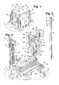
- Figure 1 is a fragmentary, perspective of a palletized load having corner protectors placed onto its vertical corners by apparatus according to a first embodiment of this invention. Three such apparatus are shown fragmentarily, a fourth being hidden by the palletized load. A machine wrapping the palletized load with a band of stretch film is shown fragmentarily.
- Figure 2 is a perspective view of one such corner protector.
- Figure 3 is a fragmentary, perspective view of one such apparatus in a "right-hand" configuration according to the first embodiment noted above.
- Figures 4, 5, 6, and 7 are sequential, schematic views showing four stages in placing the corner protectors on the palletized load by means of four such apparatus.
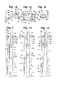
- Figure 8 is an elevational view of a magazine apart from other elements of the apparatus of Figure 3.
- Figures 9, 10, and 11 are fragmentary, elevational views showing the magazine of Figure 8 in three stages of its operation.
- Figure 12 is a fragmentary, elevational view of a wheeled cart apart from other elements of the magazine of Figure 8.
- Figure 13 is a fragmentary, plan view of a chute apart from other elements of the magazine of Figure 8.
- Figure 14 is an end view of the chute supporting the wheeled cart.
- Figures 15, 16, 17, and 18 are sequential, fragmentary, plan views showing the apparatus of Figure 3 in four stages of its operation.
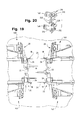
- Figure 19 is a fragmentary plan view showing each of the four apparatus in a further stage in their operation.
- Figure 20 is a fragmentary, perspective detail of a gripping mechanism of one such apparatus in a "Left-hand" configuration according to the first embodiment of this invention.
- Figure 21 is a fragmentary, perspective view of such an apparatus according to a second embodiment of this invention.
- As shown in Figure 1, a
load 10 resting on apallet 12 is being wrapped with aband 14 of stretch film by awrapping machine 16, aftercorner protectors 18 have been applied to vertical corners of theload 10 by foursimilar apparatus 20, each constituting a first embodiment of this invention. - The palletized
load 10, which may comprise stacked cartons (not shown) or other items, conforms generally to a rectangular solid. Thus, theload 10 has two pairs of opposed,vertical sides vertical corners 26 of theload 10. - The
wrapping machine 16, which is shown fragmentarily in Figure 1, may be of a type exemplified in Salzsauler U. S. Patents No. 4,934,123, and No. 4,938,008. Such wrapping machines are available from ITW-Mima (a division of Illinois Tool Works Inc.) of Boca Raton, Florida, under its COBRA trademark. - As shown in Figure 2, each
corner protector 18 has twoelongate panels 30 meeting generally at a right angle to define anoutside corner 32 and aninside corner 34. Eachelongate panel 30 has anoutside surface 36 and aninside surface 38. Eachcorner protector 18 is cut to a length equal approximately to the height of theload 10 at one of thevertical corners 26. Thecorner protectors 18 protect thevertical corners 26 against being crushed by theband 14 of stretch film as theload 10 is wrapped by thewrapping machine 16. - As shown fragmentarily in Figure 19, four
such apparatus 20 are provided, two in a "right-hand" configuration and two in a "left-hand" configuration. Theapparatus 20 at the lower left and the upper right in Figure 16 are of the "right-hand" configuration. Theapparatus 20 at the upper left and the lower right in Figure 16 are of the "left-hand" configuration. One of theapparatus 20 in the "right-hand" configuration as shown in greater detail in Figure 3, Figures 15 through 18, and other views. - As shown in Figure 3, the
apparatus 20 comprises amagazine 40 adapted to hold a supply of thecorner protectors 18 and mechanisms to be later described for removing onecorner protector 18 from themagazine 40, transferring thecorner protector 18 to a position of initial engagement, and transferring thecorner protector 18 to a position of initial engagement, and displacing thecorner protector 18 from the position of initial engagement into a position of final engagement. These successive steps are illustrated diagrammatically in Figures 4, 5, 6, and 7. - In the position of initial engagement, the
inside surface 38 of onepanel 30 of thecorner protector 18 is disposed in close proximity to onevertical side 24 of theload 10. Moreover, in such position, theinside surface 38 of theother panel 30 of thecorner protector 18 faces thevertical side 26 meeting thevertical side 24 engaged thereby. When thecorner protector 18 is displaced from the position of initial engagement into the position of final engagement, thecorner protector 18 is displaced to such extent as may be then necessary to cause theinside surface 38 of thepanel 30 facingsuch side 26 to engagesuch side 26, generally in surface-to-surface engagement. - The
magazine 40 comprises an elongate hopper orchute 60, which has alower wall 62 with anelongate slot 64 and twoside walls 66, and which is inclined forwardly and downwardly toward anoutlet end 68. Thechute 60 is affixed to apost 70, which is mounted on apedestal 72, and which is counterbalanced by ahorizontal beam 74 extending backwardly from thepost 70. Thebeam 74 has afront end 76 affixed to thepost 70 and a back end 78 (see Figure 8) mounted on apedestal 80. Thechute 60 is supported by abeam 82 inclined similarly, affixed to thepost 70, and braced by abrace 84 extending vertically between thebeam 74 and thebeam 84. - As shown in Figures 3, 12, 13, and 14, the
magazine 40 comprises awheeled carriage 90 having fourwheels 92 and being disposed movably within thechute 60, between theside walls 66. Thecarriage 90 has a centeringguide 94 with anupper handle 96 and alower hook 98. The centeringguide 96 extends downwardly through theelongate slot 64 to help in centering thecarriage 90 between theside walls 66 and in guiding thecarriage 90 along thechute 60. When it is desired to addmore corner protectors 18, thehandle 96 is convenient for moving thecarriage 90 backwardly and upwardly along thechute 60. Thehook 98 is adapted to fit under thelower wall 62, at the upper extremity of theelongate slot 64, with a frictional fit enabling thecarriage 90 to be temporarily held at such extremity whilemore corner protectors 18 are being added. - The
wheeled carriage 90 carries anupright member 100 having a substantial height compared to thecorner protectors 18. Anupper portion 102 of theupright member 100 is adapted to press against theinside corner 34 of the endmost one of thecorner protectors 18 supported by thechute 60, so as to prevent thecorner protectors 18 supported thereby from tipping backwardly, and so as to feed thecorner protectors 18 forwardly along thechute 60. Alower portion 104 of theupright member 100 extends downwardly through theelongate slot 64 to help in centering thecarriage 90 between theside walls 66 and in guiding thecarriage 90 along thechute 60. - As shown in Figures 9, 10, and 11, the
magazine 40 comprises anescapement 110, which is mounted to thepost 70 so as to be vertically movable between a lower position and an upper position. A Y-shapedretainer 112 is mounted to theescapement 110 for conjoint movement with theescapement 110. Theescapement 110 has a lower, hook-shapedportion 114, which is arranged to engage the lower end of thecorner protector 18 nearest to the outlet end 68 of thechute 60 and to elevatesuch corner protector 18 to an elevated position (see Figure 9) wheresuch corner protector 18 is removed from themagazine 40 in a manner to be later described. Ablade 116 having a lower, saw-toothed edge (see Figures 8 and 11) is mounted to thepost 70, above thenext corner protectors 18, so as to prevent more than onecorner protector 18 from being elevated at any one time. A double-acting, pneumatic, piston-cylinder mechanism 118 mounted operatively on thepost 70 is operable to move theescapement 110 between its lower position and its upper position. - Furthermore, the
magazine 40 comprises aretaining mechanism 120, which is mounted operatively on abracket 122 secured to thepost 70 in an elevated position. The position of thebracket 122 relative to thepost 70 is adjustable, within a limited range of vertical adjustment so as to accommodate corner protectors of different lengths. Theretaining mechanism 120 comprises anarm 124 having aproximal end 126 and adistal end 128 and being mounted pivotably thebracket 122, via apivot pin 138, so as to be pivotable between a vertical position and a horizontal position. In Figure 3, thearm 124 is shown in the vertical position in full lines and in the horizontal position in dashed lines. A Y-shapedretainer 132 is affixed to thedistal end 128 of thearm 124. - Moreover, the
retaining mechanism 120 comprises a double-acting, pneumatic, piston-cylinder mechanism 134, which is mounted operatively on thebracket 122. Themechanism 120 is connected to thearm 124 by alink 136, which is connected to theproximal end 126 by apivot pin 138, and is operable to pivot thearm 124 between the vertical and horizontal positions. - In the vertical position of the
arm 124, theretainer 132 engages thecorner protector 18 nearest to the outlet end 68 of thechute 60, so as to retain thecorner protectors 18 supported by thechute 60. Theretaining mechanism 120 is arranged to pivot thearm 124 from the vertical position into the horizontal position, but only when theescapement 110 has elevated thecorner protector 18 nearest to the outlet end 68 of thechute 60 to the elevated position, so as to permitsuch corner protector 18 to be then gripped (before its removal from the magazine 40) in a manner to be later described. Theescapement 110 and theretainer 112 are arranged to return to the lower position aftersuch corner protector 18 has been gripped and beforesuch corner protector 18 is removed from themagazine 40. Theretaining mechanism 120 is arranged to pivot thearm 124 from the horizontal position into the vertical position aftersuch corner protector 18 has been removed. - As shown in Figures 3, 15 through 19, and 20, the
apparatus 20 comprisesmechanisms 140 for removing onecorner protector 18 from themagazine 40, transferring thecorner protector 18 to the position of initial engagement, and displacing thecorner protector 18 from the position of initial engagement to the position of final engagement. Thecorner protector 18 to be thus removed is thecorner protector 18 nearest to the outlet end 68 of themagazine 40. Theapparatus 20 is shown in Figure 15 as removing thecorner protector 18 from themagazine 40. Theapparatus 20 is shown in Figures 16, 17, and 18 in successive stages in transferring thecorner protector 18 to the position of final engagement. Each of theapparatus 20 is shown in Figure 19 as having displaced onecorner protector 18 from its position of initial engagement into its position of final engagement. - As shown in Figure 18, the
inside surface 38 of onepanel 30 of thecorner protector 18 is disposed in close proximity to onevertical side 22 of theload 10, in the position of initial engagement. Moreover, in the position of initial engagement, theinside surface 38 of theother panel 30 of thecorner protector 18 faces thevertical side 24 meeting thevertical side 32 engaged thereby. When thecorner protector 18 is displaced from the position of initial engagement into the position of final engagement, thecorner protector 18 is displaced to such extent as may be then necessary to cause theinside surface 38 of theside panel 30 facingsuch side 24 to engagesuch side 24, generally in surface-to-surface engagement. - The
mechanisms 140 comprise apivotable structure 142 mounted pivotably in a manner to be later described, arail structure 144 mounted pivotably on thepivotable structure 142, aretractable structure 146 mounted movably on therail structure 144, and apivotable fixture 148 mounted pivotably on theretractable structure 142. - The
pivotable structure 142 is mounted pivotably on a fixedpedestal 160, via aligned upper and lower journals 162 (upper shown) so as to be pivotably movable over a limited range of pivotal motion. Thepivotable structure 142 is shown at one extreme of such range in Figures 15 and 16 and at the other extreme of such range in Figures 17 and 18. Thepivotable structure 142 includes amain beam 164 mounted pivotably on thejournals 162 and across member 166 bolted to themain beam 164 and extended at a right angle relative to themain beam 164. A double-acting, pneumatic, piston-cylinder mechanism 168 is arranged to pivot thepivotable structure 142 relative to the fixedpedestal 160, between the extremes of such range. - The
rail structure 144 comprises a pair of parallel rails 170 (see Figure 3) having acommon base 172, which is mounted pivotably on thecross member 166 of thepivotable structure 142, via apivot pin 174 shown in phantom lines. A double-acting, pneumatic,piston cylinder mechanism 178 is arranged to pivot therail structure 144 relative to thecross plate 166, over a limited range of pivotal motion. At one extreme of such range (see Figure 15) therail structure 144 is parallel to thecross member 166. At the other extreme thereof (see Figure 177 therail structure 144 defines a slight angle relative to thecross member 166. - The
retractable structure 146 comprises abox beam 180, which is parallel to therails 170 and which is mounted movably on therails 170, via a pair of guide blocks 182 enabling thebox beam 180 to move along therails 170. Theretractable structure 146 also comprises a supportingframe 184, which is bolted to thebox beam 180, via a connectingstructure 186, so as to extend at a right angle from one end of thebox beam 180. A double-acting, pneumatic, piston-cylinder mechanism 188 is arranged to move theretractable structure 146 relative to therail structure 144, between an advanced position and a retracted position. - The
pivotable fixture 148 is mounted pivotably to the supportingframe 184 via aligned upper and lower journals 190 (one shown) so as to be pivotable between an inwardly pivoted position wherein thepivotable fixture 148 is pivoted inwardly (see Figure 1 and Figures 16, 17, and 18) against the supportingframe 184 and an outwardly pivoted position wherein thepivotable fixture 148 is pivoted outwardly (see Figure 15) from the supportingframe 184. A double-acting, pneumatic, rotary motor 200 (see Figure 3) is arranged to pivot thepivotable fixture 148 relative to the supportingframe 184, between the inwardly pivoted and outwardly pivoted positions. - The
pivotable fixture 148 comprises agripping mechanism 210, which includes two similar, vertically spaced, vacuum-actuated,releasable grippers 212. Eachgripper 212 has aretractable vacuum cup 214 of a known type, which is extended to make initial engagement with anelongate panel 30 of the endmost one of thecorner protectors 18 in themagazine 40, after theescapement 110 has lifted theendmost corner protector 18 to the elevated position. Thevacuum cup 214 is retracted after such engagement has been made, and after partial vacuum has been drawn through thevacuum cup 214 to gripsuch panel 30. Thepivotable fixture 148 includes anelongate angle 220 extending vertically and generally between thegrippers 212 and defining anelongate flange 222 extending vertically. Thepivotable fixture 148 and associatedgrippers 212 of thegripping mechanism 210 of one of theapparatus 20 in the "left-hand" configuration are shown fragmentarily in Figure 20. - The
pivotable fixture 148 has arecess 230, which receives thecorner protector panel 30 gripped by the vacuum cups 214, when the vacuum cups 214 are retracted. When thecorner protector 18 havingsuch panel 30 gripped thereby is transferred to the position of initial engagement, thepivotable fixture 148 may engage onevertical side 24 of theload 10. However, becausesuch panel 30 is received by therecess 230, such panel does not engagesuch side 24 but is disposed in close proximity tosuch side 24. Theelongate flange 222 prevents thecorner protector 18 from being pulled off the vacuum cups 214 accidentally when thecorner protector 18 is being displaced from the position of initial engagement to the position of final engagement. - As shown sequentially in Figures 15 through 19, the
mechanisms 140 are operated for removing onecorner protector 18 from themagazine 40, transferring thecorner protector 18 to the position of initial engagement, and displacing thecorner protector 18 from the position of initial engagement to the position of final engagement. - Initially, the
mechanisms 140 are positioned to enable thepneumatic motor 200 to pivotpivotable fixture 148 from its inwardly pivoted position into its outwardly pivoted position, in which thegrippers 212 are positioned to engage theoutside surface 36 of oneelongate panel 30 of the endmost one of thecorner protectors 18 in themagazine 18, after theescapement 110 has gifted theendmost corner protector 18 to the elevated position. Thus, as shown in Figure 15, thepivotable structure 142 is positioned at one extreme of its limited range of pivotal motion. Also, therail structure 144 is positioned parallel to thecross member 166, and theretractable structure 146 is positioned in its retracted position - After the
pivotable fixture 148 has been pivoted into the outwardly pivoted position the vacuum cups 214 are extended and vacuum pressure is drawn through the vacuum cups 214, which gripsuch panel 30 at itsoutside surface 96. Thereupon, as shown in Figure 16, thepivotable fixture 148 is pivoted from the outwardly pivoted position into the inwardly pivoted position with the vacuum cups 214 grippingsuch panel 30, and the vacuum cups 214 are retracted. - After the vacuum cups 214 gripping
such panel 30 have been retracted, the piston-cylinder mechanism 166 is used to pivot thepivotable structure 142 to the other extreme (see Figure 17) of its limited range of pivotal motion. Therail structure 144, theretractable structure 146, and thepivotable fixture 148 are pivoted with thepivotable structure 142. Next, therail structure 144 is pivoted so as to define a slight angle (see Figure 17) relative to thecross member 166 of thepivotable structure 166. - Thereupon, the piston-
cylinder mechanism 188 is used to move theretractable structure 146 from its retracted position into the advanced position. Thus, as shown in Figure 18, thecorner protector 18 having oneelongate panel 30 gripped at itsoutside surface 36 is moved to the position of initial engagement. Theinside surface 38 of thepanel 30 gripped thereby is disposed in close proximity to onevertical side 22 of theload 10. Theinside surface 38 of theother panel 30 thereof faces thevertical side 24 meeting thevertical side 22 engaged thereby. - Thereupon, the piston-
cylinder mechanism 178 is used to pivot therail structure 144 toward and possibly beyond its position parallel with thecross member 166, as shown in Figure 19, whereby thecorner protector 18 having oneelongate panel 30 gripped at itsoutside surface 36 is moved to the position of final engagement. Thus,such corner protector 18 is displaced to such extent as may be then necessary to cause theinside surface 38 of thepanel 30 facing thevertical side 24 of theload 10 to engagesuch side 24, generally in surface-to-surface engagement. - As shown in Figure 21, in which primed reference numbers are used to designate elements designated by similar, unprimed reference numbers in the other views, an apparatus 20' for placing corner protectors onto palletized loads constitutes an alternative embodiment of this invention. The apparatus 20' is similar to the
apparatus 20 and functions similarly, except that the connecting structure 186' is simpler than the connectingstructure 186, that the pivotable fixture 148' is simpler than thepivotable fixture 148, that a double-acting, pneumatic, piston-cylinder mechanism 250 replaces the double-acting, pneumatic,rotary motor 200, and that thereleasable grippers 252 are simpler than thereleasable grippers 212, eachreleasable gripper 212 comprising avacuum cup 254 of a known, more compact type. - Various other modifications may be made in the embodiments described above without departing from the scope and spirit of this invention.
Claims (10)
Applications Claiming Priority (2)
| Application Number | Priority Date | Filing Date | Title |
|---|---|---|---|
| US07/855,263 US5226280A (en) | 1992-03-23 | 1992-03-23 | Apparatus for placing corner protectors onto palletized loads |
| US855263 | 1992-03-23 |
Publications (3)
| Publication Number | Publication Date |
|---|---|
| EP0562399A2 true EP0562399A2 (en) | 1993-09-29 |
| EP0562399A3 EP0562399A3 (en) | 1994-03-30 |
| EP0562399B1 EP0562399B1 (en) | 1996-09-25 |
Family
ID=25320790
Family Applications (1)
| Application Number | Title | Priority Date | Filing Date |
|---|---|---|---|
| EP93104134A Expired - Lifetime EP0562399B1 (en) | 1992-03-23 | 1993-03-13 | Apparatus for placing corner protectors onto palletized loads |
Country Status (13)
| Country | Link |
|---|---|
| US (1) | US5226280A (en) |
| EP (1) | EP0562399B1 (en) |
| JP (1) | JPH0767980B2 (en) |
| KR (1) | KR960008700B1 (en) |
| AT (1) | ATE143323T1 (en) |
| AU (1) | AU644548B2 (en) |
| CA (1) | CA2091639C (en) |
| DE (1) | DE69304965T2 (en) |
| ES (1) | ES2092156T3 (en) |
| FI (1) | FI101952B1 (en) |
| NO (1) | NO931036L (en) |
| NZ (1) | NZ247203A (en) |
| TW (1) | TW216415B (en) |
Cited By (3)
| Publication number | Priority date | Publication date | Assignee | Title |
|---|---|---|---|---|
| WO2003018403A2 (en) * | 2001-08-24 | 2003-03-06 | Lantech.Com, Llc | Apparatus and method for applying cornerboards to a load and wrapping it |
| EP1491447A1 (en) * | 2003-06-27 | 2004-12-29 | AETNA GROUP S.p.A. | Apparatus and method for applying corner elements to palletised loads |
| WO2006130404A1 (en) * | 2005-05-31 | 2006-12-07 | Illinois Tool Works Inc. | Apparatus for applying external corner or edge protectors onto external corner or edge regions of packages or palletized loads |
Families Citing this family (31)
| Publication number | Priority date | Publication date | Assignee | Title |
|---|---|---|---|---|
| FR2669002B1 (en) * | 1990-11-09 | 1994-10-28 | Newtec Int | METHOD, MACHINE AND INSTALLATION FOR PACKAGING A LOAD PROVIDED WITH AT LEAST ONE HINGE PROTECTION HINGE; DEVICE FOR SEIZING, MOVING, DEPOSITING AND HOLDING SUCH A CORNER. |
| IT1266327B1 (en) * | 1993-05-05 | 1996-12-27 | Sorma Srl | DEVICE FOR APPLICATION OF CORNERS TO PALLETS. |
| US5535572A (en) * | 1993-06-30 | 1996-07-16 | Illinois Tool Works Inc. | Apparatus for placing corner protectors and top protectors on palletized loads |
| US6439383B1 (en) * | 1994-01-18 | 2002-08-27 | Saint-Gobain Vetrotex America, Inc. | Packaging for shipment of fiber glass rovings |
| US5546730A (en) * | 1994-03-31 | 1996-08-20 | Lantech, Inc. | Method and apparatus for placing corner boards and stretch wrapping a load |
| US5596863A (en) * | 1995-06-12 | 1997-01-28 | Illinois Tool Works Inc. | Method and apparatus for applying edge protectors |
| US5647191A (en) * | 1995-12-21 | 1997-07-15 | Domtar Inc. | Assembly of packaged reams and method therefor |
| US5758470A (en) * | 1996-08-28 | 1998-06-02 | Lantech, Inc. | Method and apparatus for placing cornerboards and wrapping a load |
| US5950400A (en) * | 1996-10-31 | 1999-09-14 | C & S Associates | Apparatus and method for protecting rolled material |
| US6178721B1 (en) | 1999-03-04 | 2001-01-30 | Illinois Tool Works Inc. | Apparatus and method for placing corner protectors of different heights on palletized |
| FI20001546A0 (en) * | 2000-06-29 | 2000-06-29 | Haloila M Oy Ab | Device for placing a corner guard on a corner of a package and arrangement for protecting a package |
| WO2002031366A2 (en) * | 2000-10-13 | 2002-04-18 | Parcels Joseph S | Automatic tandem corner protector attachment method and apparatus for picture frames and the like |
| SE522005C2 (en) * | 2002-05-28 | 2004-01-07 | Inter Ikea Systems Bv | Application of loading lists |
| WO2005063581A1 (en) * | 2003-12-24 | 2005-07-14 | Sanchez Renasco Jesus | Method of handling corner pieces for the packaging of palletised loads and similar |
| US20060168911A1 (en) * | 2005-02-03 | 2006-08-03 | Willamette Valley Company | System and method for installing a protective covering onto a stack of work pieces |
| US7823896B2 (en) * | 2006-02-01 | 2010-11-02 | Ford Global Technologies | Articulated step system for automotive vehicle |
| US20110180450A1 (en) * | 2010-01-26 | 2011-07-28 | Great Northern Corporation | Products and method for packaging multiple rows of products |
| CA2812973C (en) | 2010-08-26 | 2018-09-11 | Mollers North America, Inc. | Corner post application system |
| US9394069B2 (en) | 2011-09-30 | 2016-07-19 | Brenton Llc | Corner protector placement system and method and related pallet wrapping system and method |
| FI125661B (en) * | 2012-09-07 | 2015-12-31 | Signode Int Ip Holdings Llc | Method and apparatus for attaching corner guard to a load |
| CN103723299A (en) * | 2012-10-10 | 2014-04-16 | 鸿富锦精密工业(深圳)有限公司 | Edge covering device |
| DE102015113350A1 (en) * | 2015-08-13 | 2017-02-16 | Signode Industrial Group Llc | Strapping device for packages and method of strapping |
| SE540413C2 (en) * | 2016-05-25 | 2018-09-11 | Wallenius Water Innovation Ab | A UV light liquid treatment system |
| CN108238318B (en) * | 2017-03-09 | 2020-03-17 | 苏州德睿联自动化科技有限公司 | Automatic corner protection wrapping machine |
| CN107902125B (en) * | 2017-11-17 | 2020-12-18 | 新昌县宇力铸造有限公司 | Sheet plastic waste recycling handles batch binding apparatus |
| DE102019107702B3 (en) | 2019-03-26 | 2020-05-28 | Signode Industrial Group Llc | Method for arranging an edge protection agent on a package in a device for strapping packages and device for strapping packages |
| CN113277186A (en) * | 2020-02-20 | 2021-08-20 | 阳程科技股份有限公司 | Corner protector placing machine |
| CN112478295B (en) * | 2020-11-18 | 2022-02-01 | 浙江旭派克智能科技有限公司 | Corner protector |
| CN113291518B (en) * | 2021-05-18 | 2022-10-28 | 浙江百事特包装科技股份有限公司 | But baling press of automatic installation protection architecture |
| CN113443235B (en) * | 2021-07-20 | 2023-03-24 | 青岛欣欣向荣智能设备有限公司 | Packaging equipment with corner protector automatic feeding function and control method thereof |
| CN114802990B (en) * | 2022-06-28 | 2022-09-30 | 江苏帝全自动化机械有限公司 | Can prevent to extrude case sealer of packing material |
Citations (5)
| Publication number | Priority date | Publication date | Assignee | Title |
|---|---|---|---|---|
| US3241287A (en) * | 1962-08-14 | 1966-03-22 | Jr Louis W Chundelak | Apparatus for strapping packages |
| DE2431153A1 (en) * | 1974-06-28 | 1976-01-15 | Hoffmann Cyklop | Packaging machine for stacks of bricks - has magazine and grab for automatic application of protective corner strips |
| EP0060543A2 (en) * | 1981-03-16 | 1982-09-22 | Hellmann GmbH | Appliance for laying header bends on bulk goods |
| US4897980A (en) * | 1989-06-05 | 1990-02-06 | James River Corporation | Apparatus for forming a bulk package |
| WO1992008644A1 (en) * | 1990-11-09 | 1992-05-29 | Newtec International | Method, machine and assembly for packing a load provided with at least one edge-protecting corner piece, and device for grasping, moving, depositing and holding said corner piece |
Family Cites Families (6)
| Publication number | Priority date | Publication date | Assignee | Title |
|---|---|---|---|---|
| US1418153A (en) * | 1922-01-06 | 1922-05-30 | Lorber Charles | Bread server |
| US3378987A (en) * | 1965-04-29 | 1968-04-23 | Signode Corp | Edge protector applicator |
| GB1210491A (en) * | 1966-10-12 | 1970-10-28 | Mardon Son & Hall Ltd | Removing sheet like articles from a stack |
| FI853775L (en) * | 1985-09-30 | 1987-04-22 | Haloila M Oy Ab | FOERFARANDE FOER ATT LINDA IN KAKET SOM BESTAOR AV VAESENTLIGEN REAKTANGULAERA PRODUKTER SOM SKALL PACKAS IN OCH EN VID FOERFARANDET ANVAEND FORMNINGS- OCH OEVERFOERINGSANORDNING FOER STOEDORGANEN AV DE FOERPACKADE PROD |
| US4938008A (en) * | 1987-07-10 | 1990-07-03 | Roy Salzsauler | Pallet wrapping apparatus |
| US4934123A (en) * | 1988-02-25 | 1990-06-19 | Roy Salzsauler | Carriage |
-
1992
- 1992-03-23 US US07/855,263 patent/US5226280A/en not_active Expired - Fee Related
-
1993
- 1993-03-12 AU AU35202/93A patent/AU644548B2/en not_active Ceased
- 1993-03-13 ES ES93104134T patent/ES2092156T3/en not_active Expired - Lifetime
- 1993-03-13 AT AT93104134T patent/ATE143323T1/en not_active IP Right Cessation
- 1993-03-13 DE DE69304965T patent/DE69304965T2/en not_active Expired - Fee Related
- 1993-03-13 EP EP93104134A patent/EP0562399B1/en not_active Expired - Lifetime
- 1993-03-15 CA CA002091639A patent/CA2091639C/en not_active Expired - Fee Related
- 1993-03-18 JP JP5082429A patent/JPH0767980B2/en not_active Expired - Fee Related
- 1993-03-19 NZ NZ24720393A patent/NZ247203A/en unknown
- 1993-03-22 FI FI931241A patent/FI101952B1/en active
- 1993-03-22 KR KR1019930004389A patent/KR960008700B1/en not_active IP Right Cessation
- 1993-03-22 NO NO93931036A patent/NO931036L/en unknown
- 1993-06-16 TW TW082104798A patent/TW216415B/zh active
Patent Citations (5)
| Publication number | Priority date | Publication date | Assignee | Title |
|---|---|---|---|---|
| US3241287A (en) * | 1962-08-14 | 1966-03-22 | Jr Louis W Chundelak | Apparatus for strapping packages |
| DE2431153A1 (en) * | 1974-06-28 | 1976-01-15 | Hoffmann Cyklop | Packaging machine for stacks of bricks - has magazine and grab for automatic application of protective corner strips |
| EP0060543A2 (en) * | 1981-03-16 | 1982-09-22 | Hellmann GmbH | Appliance for laying header bends on bulk goods |
| US4897980A (en) * | 1989-06-05 | 1990-02-06 | James River Corporation | Apparatus for forming a bulk package |
| WO1992008644A1 (en) * | 1990-11-09 | 1992-05-29 | Newtec International | Method, machine and assembly for packing a load provided with at least one edge-protecting corner piece, and device for grasping, moving, depositing and holding said corner piece |
Cited By (8)
| Publication number | Priority date | Publication date | Assignee | Title |
|---|---|---|---|---|
| WO2003018403A2 (en) * | 2001-08-24 | 2003-03-06 | Lantech.Com, Llc | Apparatus and method for applying cornerboards to a load and wrapping it |
| WO2003018403A3 (en) * | 2001-08-24 | 2003-10-30 | Lantech Com Llc | Apparatus and method for applying cornerboards to a load and wrapping it |
| US6883293B2 (en) | 2001-08-24 | 2005-04-26 | Lantech.Com, Llp | Apparatus and method for applying cornerboards to a load |
| US6990784B2 (en) | 2001-08-24 | 2006-01-31 | Lantech.Com, Llc | Apparatus and method for applying cornerboards to a load |
| EP1491447A1 (en) * | 2003-06-27 | 2004-12-29 | AETNA GROUP S.p.A. | Apparatus and method for applying corner elements to palletised loads |
| US7325371B2 (en) | 2003-06-27 | 2008-02-05 | Aetna Group, S.P.A. | Apparatus for applying corner elements to palletized loads |
| US7748198B2 (en) | 2003-06-27 | 2010-07-06 | Aetna Group S.P.A. | Apparatus and method for applying corner elements to palletized loads |
| WO2006130404A1 (en) * | 2005-05-31 | 2006-12-07 | Illinois Tool Works Inc. | Apparatus for applying external corner or edge protectors onto external corner or edge regions of packages or palletized loads |
Also Published As
| Publication number | Publication date |
|---|---|
| AU3520293A (en) | 1993-10-07 |
| FI931241A (en) | 1993-09-24 |
| TW216415B (en) | 1993-11-21 |
| NO931036L (en) | 1993-09-24 |
| US5226280A (en) | 1993-07-13 |
| FI101952B (en) | 1998-09-30 |
| KR960008700B1 (en) | 1996-06-29 |
| CA2091639C (en) | 1995-08-01 |
| AU644548B2 (en) | 1993-12-09 |
| EP0562399A3 (en) | 1994-03-30 |
| JPH0767980B2 (en) | 1995-07-26 |
| FI931241A0 (en) | 1993-03-22 |
| NO931036D0 (en) | 1993-03-22 |
| DE69304965D1 (en) | 1996-10-31 |
| ATE143323T1 (en) | 1996-10-15 |
| EP0562399B1 (en) | 1996-09-25 |
| KR930019515A (en) | 1993-10-18 |
| DE69304965T2 (en) | 1997-02-06 |
| NZ247203A (en) | 1994-07-26 |
| FI101952B1 (en) | 1998-09-30 |
| JPH06135566A (en) | 1994-05-17 |
| ES2092156T3 (en) | 1996-11-16 |
Similar Documents
| Publication | Publication Date | Title |
|---|---|---|
| EP0562399B1 (en) | Apparatus for placing corner protectors onto palletized loads | |
| US10631465B2 (en) | Bagging assembly | |
| AU2009222003B2 (en) | Bagging assembly | |
| US6860531B2 (en) | Gripping and vacuum end effector for transferring articles | |
| US5127695A (en) | Apparatus for manipulating a pallet | |
| EP1724219B1 (en) | Apparatus and method for the palletisation of articles | |
| US6056496A (en) | Cart loader and method of loading | |
| GB2340817A (en) | Combined friction and suction grippers | |
| US4527940A (en) | Cheese unloading machine | |
| US4234280A (en) | Palletizer | |
| JP2849992B2 (en) | Skid insertion device | |
| CN212313951U (en) | Automatic special angle bead mounting machine device | |
| CN217477624U (en) | Full-automatic many specifications ceramic tile packing assembly line | |
| CN219620368U (en) | Unstacking structure and fresh box mouth-cutting flow production line with unstacking structure | |
| CN213415565U (en) | Found package upset hacking machine | |
| US20240076078A1 (en) | Corner post application system | |
| JPH0735631Y2 (en) | Plate material storage and transportation device | |
| JPS6259004B2 (en) | ||
| CN114313392A (en) | Full-automatic many specifications ceramic tile packing assembly line | |
| JPH0129668B2 (en) | ||
| JPH08282844A (en) | Palletizer | |
| JPH0776005B2 (en) | Packing method and packing device using packing sheet | |
| JPH068927A (en) | Cutting device for packing band wound around case | |
| JPH10114431A (en) | Container piling up device | |
| CS228056B1 (en) | Equipment for lifting of packages of textile and similar materials from flat pallets of cutting tables |
Legal Events
| Date | Code | Title | Description |
|---|---|---|---|
| PUAI | Public reference made under article 153(3) epc to a published international application that has entered the european phase |
Free format text: ORIGINAL CODE: 0009012 |
|
| 17P | Request for examination filed |
Effective date: 19930313 |
|
| AK | Designated contracting states |
Kind code of ref document: A2 Designated state(s): AT BE CH DE DK ES FR GB GR IE IT LI LU MC NL PT SE |
|
| PUAL | Search report despatched |
Free format text: ORIGINAL CODE: 0009013 |
|
| AK | Designated contracting states |
Kind code of ref document: A3 Designated state(s): AT BE CH DE DK ES FR GB GR IE IT LI LU MC NL PT SE |
|
| 17Q | First examination report despatched |
Effective date: 19950510 |
|
| GRAG | Despatch of communication of intention to grant |
Free format text: ORIGINAL CODE: EPIDOS AGRA |
|
| GRAH | Despatch of communication of intention to grant a patent |
Free format text: ORIGINAL CODE: EPIDOS IGRA |
|
| GRAH | Despatch of communication of intention to grant a patent |
Free format text: ORIGINAL CODE: EPIDOS IGRA |
|
| GRAA | (expected) grant |
Free format text: ORIGINAL CODE: 0009210 |
|
| AK | Designated contracting states |
Kind code of ref document: B1 Designated state(s): AT BE CH DE DK ES FR GB GR IE IT LI LU MC NL PT SE |
|
| PG25 | Lapsed in a contracting state [announced via postgrant information from national office to epo] |
Ref country code: LI Effective date: 19960925 Ref country code: IT Free format text: LAPSE BECAUSE OF FAILURE TO SUBMIT A TRANSLATION OF THE DESCRIPTION OR TO PAY THE FEE WITHIN THE PRESCRIBED TIME-LIMIT;WARNING: LAPSES OF ITALIAN PATENTS WITH EFFECTIVE DATE BEFORE 2007 MAY HAVE OCCURRED AT ANY TIME BEFORE 2007. THE CORRECT EFFECTIVE DATE MAY BE DIFFERENT FROM THE ONE RECORDED. Effective date: 19960925 Ref country code: GR Free format text: LAPSE BECAUSE OF FAILURE TO SUBMIT A TRANSLATION OF THE DESCRIPTION OR TO PAY THE FEE WITHIN THE PRESCRIBED TIME-LIMIT Effective date: 19960925 Ref country code: DK Effective date: 19960925 Ref country code: CH Effective date: 19960925 Ref country code: BE Effective date: 19960925 |
|
| REF | Corresponds to: |
Ref document number: 143323 Country of ref document: AT Date of ref document: 19961015 Kind code of ref document: T |
|
| REF | Corresponds to: |
Ref document number: 69304965 Country of ref document: DE Date of ref document: 19961031 |
|
| REG | Reference to a national code |
Ref country code: IE Ref legal event code: FG4D Free format text: 70000 |
|
| REG | Reference to a national code |
Ref country code: ES Ref legal event code: FG2A Ref document number: 2092156 Country of ref document: ES Kind code of ref document: T3 |
|
| PG25 | Lapsed in a contracting state [announced via postgrant information from national office to epo] |
Ref country code: SE Effective date: 19961225 |
|
| PG25 | Lapsed in a contracting state [announced via postgrant information from national office to epo] |
Ref country code: PT Effective date: 19961226 |
|
| ET | Fr: translation filed | ||
| PG25 | Lapsed in a contracting state [announced via postgrant information from national office to epo] |
Ref country code: IE Free format text: LAPSE BECAUSE OF NON-PAYMENT OF DUE FEES Effective date: 19970313 |
|
| REG | Reference to a national code |
Ref country code: CH Ref legal event code: PL |
|
| PG25 | Lapsed in a contracting state [announced via postgrant information from national office to epo] |
Ref country code: LU Free format text: LAPSE BECAUSE OF NON-PAYMENT OF DUE FEES Effective date: 19970331 |
|
| PLBE | No opposition filed within time limit |
Free format text: ORIGINAL CODE: 0009261 |
|
| STAA | Information on the status of an ep patent application or granted ep patent |
Free format text: STATUS: NO OPPOSITION FILED WITHIN TIME LIMIT |
|
| 26N | No opposition filed | ||
| PG25 | Lapsed in a contracting state [announced via postgrant information from national office to epo] |
Ref country code: MC Effective date: 19970930 |
|
| PGFP | Annual fee paid to national office [announced via postgrant information from national office to epo] |
Ref country code: FR Payment date: 19980221 Year of fee payment: 6 |
|
| PGFP | Annual fee paid to national office [announced via postgrant information from national office to epo] |
Ref country code: NL Payment date: 19980223 Year of fee payment: 6 Ref country code: DE Payment date: 19980223 Year of fee payment: 6 Ref country code: AT Payment date: 19980223 Year of fee payment: 6 |
|
| PGFP | Annual fee paid to national office [announced via postgrant information from national office to epo] |
Ref country code: GB Payment date: 19980226 Year of fee payment: 6 |
|
| PG25 | Lapsed in a contracting state [announced via postgrant information from national office to epo] |
Ref country code: GB Free format text: LAPSE BECAUSE OF NON-PAYMENT OF DUE FEES Effective date: 19990313 Ref country code: AT Free format text: LAPSE BECAUSE OF NON-PAYMENT OF DUE FEES Effective date: 19990313 |
|
| PGFP | Annual fee paid to national office [announced via postgrant information from national office to epo] |
Ref country code: ES Payment date: 19990316 Year of fee payment: 7 |
|
| PG25 | Lapsed in a contracting state [announced via postgrant information from national office to epo] |
Ref country code: NL Free format text: LAPSE BECAUSE OF NON-PAYMENT OF DUE FEES Effective date: 19991001 |
|
| GBPC | Gb: european patent ceased through non-payment of renewal fee |
Effective date: 19990313 |
|
| PG25 | Lapsed in a contracting state [announced via postgrant information from national office to epo] |
Ref country code: FR Free format text: LAPSE BECAUSE OF NON-PAYMENT OF DUE FEES Effective date: 19991130 |
|
| NLV4 | Nl: lapsed or anulled due to non-payment of the annual fee |
Effective date: 19991001 |
|
| REG | Reference to a national code |
Ref country code: FR Ref legal event code: ST |
|
| PG25 | Lapsed in a contracting state [announced via postgrant information from national office to epo] |
Ref country code: DE Free format text: LAPSE BECAUSE OF NON-PAYMENT OF DUE FEES Effective date: 20000101 |
|
| PG25 | Lapsed in a contracting state [announced via postgrant information from national office to epo] |
Ref country code: ES Free format text: LAPSE BECAUSE OF NON-PAYMENT OF DUE FEES Effective date: 20000314 |
|
| REG | Reference to a national code |
Ref country code: ES Ref legal event code: FD2A Effective date: 20010910 |