EP0560637B1 - Laser irradiation nozzle and laser apparatus using the same - Google Patents
Laser irradiation nozzle and laser apparatus using the same Download PDFInfo
- Publication number
- EP0560637B1 EP0560637B1 EP93301950A EP93301950A EP0560637B1 EP 0560637 B1 EP0560637 B1 EP 0560637B1 EP 93301950 A EP93301950 A EP 93301950A EP 93301950 A EP93301950 A EP 93301950A EP 0560637 B1 EP0560637 B1 EP 0560637B1
- Authority
- EP
- European Patent Office
- Prior art keywords
- nozzle
- laser
- laser beam
- assist gas
- laser irradiation
- Prior art date
- Legal status (The legal status is an assumption and is not a legal conclusion. Google has not performed a legal analysis and makes no representation as to the accuracy of the status listed.)
- Expired - Lifetime
Links
Images






Classifications
-
- B—PERFORMING OPERATIONS; TRANSPORTING
- B23—MACHINE TOOLS; METAL-WORKING NOT OTHERWISE PROVIDED FOR
- B23K—SOLDERING OR UNSOLDERING; WELDING; CLADDING OR PLATING BY SOLDERING OR WELDING; CUTTING BY APPLYING HEAT LOCALLY, e.g. FLAME CUTTING; WORKING BY LASER BEAM
- B23K26/00—Working by laser beam, e.g. welding, cutting or boring
- B23K26/14—Working by laser beam, e.g. welding, cutting or boring using a fluid stream, e.g. a jet of gas, in conjunction with the laser beam; Nozzles therefor
-
- B—PERFORMING OPERATIONS; TRANSPORTING
- B23—MACHINE TOOLS; METAL-WORKING NOT OTHERWISE PROVIDED FOR
- B23K—SOLDERING OR UNSOLDERING; WELDING; CLADDING OR PLATING BY SOLDERING OR WELDING; CUTTING BY APPLYING HEAT LOCALLY, e.g. FLAME CUTTING; WORKING BY LASER BEAM
- B23K26/00—Working by laser beam, e.g. welding, cutting or boring
- B23K26/14—Working by laser beam, e.g. welding, cutting or boring using a fluid stream, e.g. a jet of gas, in conjunction with the laser beam; Nozzles therefor
- B23K26/1462—Nozzles; Features related to nozzles
- B23K26/1464—Supply to, or discharge from, nozzles of media, e.g. gas, powder, wire
- B23K26/1476—Features inside the nozzle for feeding the fluid stream through the nozzle
-
- B—PERFORMING OPERATIONS; TRANSPORTING
- B23—MACHINE TOOLS; METAL-WORKING NOT OTHERWISE PROVIDED FOR
- B23K—SOLDERING OR UNSOLDERING; WELDING; CLADDING OR PLATING BY SOLDERING OR WELDING; CUTTING BY APPLYING HEAT LOCALLY, e.g. FLAME CUTTING; WORKING BY LASER BEAM
- B23K26/00—Working by laser beam, e.g. welding, cutting or boring
- B23K26/14—Working by laser beam, e.g. welding, cutting or boring using a fluid stream, e.g. a jet of gas, in conjunction with the laser beam; Nozzles therefor
- B23K26/142—Working by laser beam, e.g. welding, cutting or boring using a fluid stream, e.g. a jet of gas, in conjunction with the laser beam; Nozzles therefor for the removal of by-products
-
- B—PERFORMING OPERATIONS; TRANSPORTING
- B23—MACHINE TOOLS; METAL-WORKING NOT OTHERWISE PROVIDED FOR
- B23K—SOLDERING OR UNSOLDERING; WELDING; CLADDING OR PLATING BY SOLDERING OR WELDING; CUTTING BY APPLYING HEAT LOCALLY, e.g. FLAME CUTTING; WORKING BY LASER BEAM
- B23K26/00—Working by laser beam, e.g. welding, cutting or boring
- B23K26/20—Bonding
- B23K26/21—Bonding by welding
Definitions
- Laser welding apparatuses are included in the application fields of laser processing.
- a plasma which considerably affects the behavior of the molten value, is generated during the process. Accordingly, shield gas is generally blown during the welding to remove the plasma. Furthermore, because fumes and sputters adhere to the nozzle of the laser thereby impairing the optical system, measures for preventing them from forming have also been studied.
- Shield gas blowing can be carried out by either a center gas type process or a side gas type process.
- the gas is blown co-axially with the laser beam.
- This process is mostly used for laser cutting (for examples as published in JP58-2754 and JP59-37159).
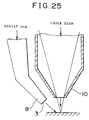
- a gas is blown to the weld through a path other than the laser beam as shown in FIG. 25.
- This type of gas blowing is carried out using a side nozzle, and is utilized for suppressing the plasma and for improving the welding bead (for examples as published in JP60-32556 and laid opened JP58-168490).
- ring-shaped nozzles are used. Such nozzles are used for concentrating the shield gas, as disclosed in, for example, JP56-151191 (laid opened), on which the precharacterising portion of appended claim 1 is based. They are also used for preventing the adhesion of metal melt during cutting, as disclosed, for example, JP03-23275 (published). A similar device is also disclosed in DE-A-3637568.
- shield gas gases of rare elements such as Ar, He, Xe, Kr, and Ne; inert gases such as N2; and reactive gases such as CO2 and H2; as well as the gases obtained by mixing two or more gases selected therefrom.
- a laser processing process which comprises blowing an inert gas against the laser irradiated portion through a ring-shaped nozzle is disclosed in JP56-151191(laid opened) referred to herein before (see Figs. 2 and 4 attached thereto).
- JP56-151191 (laid opened) referred to herein before (see Figs. 2 and 4 attached thereto).
- no consideration is made on the angle between the inner and the outer nozzles and on the positional relation between the nozzles and the workpiece. Accordingly, the problems (1) to (6) as enumerated above remain yet to be solved.
- An object of the present invention is to provide a laser irradiation nozzle and apparatus with at least one of the problems above reduced; and a laser irradiation nozzle and apparatus in which the nozzle clogging is hindered from occurring, in which the adhesion of metal oxides is hindered which enables a non-directional gas blowing, which provides sound bead morphology, which hinders oxidation from occurring on the weld, and which provides a stable penetration depth of the work.
- the present invention also provides a laser irradiating nozzle according to claim 2.
- ⁇ 0 is preferably in the range of from 10 to 30 degrees.
- the value of k is preferably not less than 1 and not higher than 2; more preferably, it is not less than 1.05 and not higher than 1.50.
- the laser irradiation nozzle of the present invention is shaped as such that it satisfies the relations as follows to prevent nozzle top from suffering clogging, to obtain a sound bead morphology, to obtain a sufficient penetration depth, and the like.
- the shape of said nozzle most preferably satisfy the relations as follows (1-2) ⁇ ⁇ -(3/5)h + 34 (2-2) ⁇ ⁇ -(3/5)h + 19 25 ⁇ h ⁇ 15
- a laser irradiation nozzle having the ratio ⁇ (%) as specified above can be obtained be simply processing the outside accurately to the defined ⁇ S value without any restriction on which method to take for realizing the specified dimension.
- the assist gas is supplied from the assist gas outlet at a flow rate of 10 l/min or higher.
- Preferred materials for the inside and outside nozzles of the laser irradiation nozzles according to the present invention include an alloy containing a transition metal as the principal component, such as an aluminum (Al) alloy, a copper (Cu) alloy, a carbon steel, a stainless steel, a titanium (Ti) alloy, a magnesium (Mg) alloy, and a molybdenum (Mo) alloy; or a composite material based on the alloys above, having rendered heat resistant and hardened by providing thereon a coating of a metallic material (e.g., W, Ta, Mo, and V), or a ceramic material (e.g., an oxide, a nitride, a boride, etc., of the metals above), by a method such as spraying, CVD (chemical vapor deposition), PVD (physical vapor deposition), and nitriding or carburizing.
- a transition metal as the principal component
- a metallic material e.g., W, Ta, Mo, and V
- the laser irradiation nozzle according to the present invention can be manufactured at a low cost machining such as cutting using the materials enumerated above.
- the weld materials to be used in the present invention include an alloy containing a transition metal as the principal component, such as an Al alloy, a Cu alloy, an alloy steel, a carbon steel, a stainless steel, a nickel (Ni) alloy, a zinc (Zn) alloy, an Mg alloy, a Mo alloy, and a Ti alloy.
- a transition metal such as an Al alloy, a Cu alloy, an alloy steel, a carbon steel, a stainless steel, a nickel (Ni) alloy, a zinc (Zn) alloy, an Mg alloy, a Mo alloy, and a Ti alloy.
- the present invention provides a laser irradiation nozzle for use at a specified distance between the focal point of the laser beam with respect to the work and the nozzle top, and a specified ratio of the cross sectional area of the space between the top of the inside nozzle and the top of the outside nozzle 1, from which the assist gas is supplied, to the cross sectional area defined by the outer diameter of said top of the inside nozzle.
- the laser irradiation nozzle according to the present invention having the structure above enables an assist gas blowing having little directionality and which provides a sound bead morphology, welds substantially free from oxidation, and keeping sufficient depth.
- the use of the laser irradiation nozzle according to the present invention on an assist gas blowing process effectively hinders the nozzle from clogging and adhesion of metal oxides.
- a laser power source 17 supplied with an AC of 400 V supplies a predetermined electric power to a laser head 18, and the laser beam having generated from the laser head 18 at a predetermined frequency is introduced to a laser emission unit (laser irradiation nozzle) 20 via an optical fiber F.
- the laser power source 17 and the laser head 18 are chilled by circulating a coolant providing from a cooler 21 to prevent the laser power source and the laser head from being overheated.
- the movement of the irradiating unit 20 along the XYZ directions and the ⁇ angular direction is controlled by a driving stage 22 and an arm 23.
- the driving stage 22 and the arm 23 are controlled by a control system comprising a display 24, a laser controller 25, a programming box 26, and a robot control unit 27.
- an assist gas (Ar gas) source 28 and an air compressor 30 are connected to the top of the laser emission unit 20.
- the structure of the top of the irradiation unit 20, i.e., the structure of the irradiation nozzle, is described in further detail below referring to Figs. 1 to 5.
- FIG. 5 is shown a laser irradiation nozzle according to an Example, having a structure characteristic to the present invention.
- the laser emission unit 20 is connected to the top of the optical fiber F.
- the present unit includes two internal lenses 4a and 4b inside the cylindrical shell 5, and a cylinder top 6 being joined to the cylindrical shell 5. Further to the cylinder top 6 is provided a tapered nozzle portion 8. As shown in Figs. 1 and 2, the nozzle portion 8 comprises a conical outside nozzle 1 and an inside nozzle 2 being arranged concentrically, to provide a double layered trapezoid structure, i.e., a cone having its head cut with a plane at a certain distance from the top. In this manner, an assist gas outlet 3 for ejecting the assist gas (against the surface of the weld specimen) can be opened between the outside nozzle 1 and the inside nozzle 2. Furthermore, a laser emission outlet 10 is opened at the top of the inside nozzle 2 to emit therefrom a laser beam concentrated by the lenses 4a and 4b.
- the inside nozzle 2 has an inner shape being machined into a hemispherical cone, such that the inner side may not interfere with the path of the laser beam.
- the outside nozzle (illustrated schematically in Fig 1) is shaped into a cone having its outer plane being tilted at an angle of ⁇ with respect to the center axis thereof, and an apex of the cone corresponding to the focal point of the laser beam.
- a gas flow path 12 which connects the assist gas source with the assist gas outlet 3 via a gas introduction portion 16 is defined between the outside nozzle 1 and the inside nozzle 2.
- a transparent protective glass 9 is inserted between the laser emission outlet 10 the lense 4b.
- the laser emission unit as described above was used in an experimental welding.
- a laser apparatus equipped with a pulsed YAG laser (wavelength: 1.06 ⁇ m) operating in multi-mode at an average power output of 480 W and at a repetition of 8 pps was used in the experiment.
- the specimen used in the welding was prepared by welding two lap-jointed JIS A5052 sheets, each 100 mm in length, 30 mm in width, and 1.0 mm in thickness. The welding was conducted at a welding rate of 50 cm/min for a length of 20 mm, using argon (Ar) as the assist gas.
- the distance between the laser beam focal plane of image-formation side and the top of the nozzle h was changed, and the nozzle area ratio ⁇ (%) was varied accordingly for each of the changed h values to observe the influence on the shape of weld beads with the changing parameters. More specifically, the value h was varied in 6 levels, i.e., 5, 10, 20, 30, 40, and 50 mm. The ⁇ (%) was varied for each of the h values in 5 levels to prepare 30 types in total of laser irradiation nozzles. The rate of the assist gas flow was varied in the range of from 0 to 40 l/min.
- the weld beads were evaluated for the following items: external appearance of the bead shape such as disturbed bead shape; adhesion of the metal oxide to the surface of the specimen; oxidation degree of the surface of the specimen; clogging of the top of the laser irradiation nozzle due to the formation of sputters and fume; and the influence on the weld depth.
- the conditions marked with X correspond to unfavorable ones under which disordering of molten metal due to excessively high flow rate, i.e., humping beads, and undercuts of the beads are observed; the external appearance of such beads can be observed in FIG. 11.
- Those marked with ⁇ are acceptable conditions, under which some undercuts may be observed on the bead, but rather, under which a somewhat humping bead appearance; this can be observed in FIG. 12.
- Those marked with ⁇ are favorable conditions under which favorable bead shapes can be observed as shown in the photograph of FIG. 13.
- the results for the evaluation of the adhesion of metal oxides under each of the welding conditions enumerated above are summarized in FIG. 7.
- the conditions marked with X correspond to unfavorable ones under which the adhesion of a considerable amount of black colored metal oxides over a wide area is observed: the external appearance of such beads can be observed in the photograph given in FIG. 14.
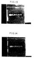
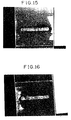
- Those marked with ⁇ are acceptable conditions, under which beads having metal oxides adhered over a reduced area as compared to those observed under conditions marked with X are obtained; this can be observed in the photograph of FIG. 15.
- Those marked with ⁇ are favorable conditions under which favorable bead appearances having little adhesion of metal oxides can be observed, as shown in the photograph of FIG. 16.
- the evaluation results under each of the welding conditions are summarized in FIG. 8.
- the conditions marked with X correspond to unfavorable ones under which a considerable amount of white colored surface oxidized region is observed to spread over a wide area; the external appearance of such beads can be observed in the photograph given in FIG. 17.
- Those marked with ⁇ are acceptable conditions, under which beads having an oxidized region being spread over a reduced area as compared to those observed under conditions marked with X are obtained; this can be observed in the photograph of FIG. 18.
- Those marked with ⁇ are favorable conditions under which favorable bead appearances having little formation of oxidized are obtained, as shown in the photograph of FIG. 17.
- the evaluation results under each of the welding conditions are summarized in FIG. 9.
- the conditions marked with X correspond to unfavorable ones under which the weld sputters and fume are observed to adhere to the top of the laser irradiation nozzle; under such conditions.
- the top of the nozzle suffer inconveniences such as clogging due to the sputters and the like, which leads to a disturbed assist gas ejection, or, even worse, to a complete cease of the assist gas flow.
- Those marked with ⁇ are favorable conditions under which no adhesion of weld sputters and fume is observed.
- region I is defined by: (1-1) ⁇ ⁇ -(3/5)h + 36 (2-1) ⁇ ⁇ -(3/5)h + 16 ⁇ > 0, h ⁇ 10 region II is defined by: (1-2) ⁇ ⁇ -(3/5)h + 34 (2-2) ⁇ ⁇ -(3/5)h + 19 ⁇ ⁇ 2.5, h ⁇ 15 and region III is defined by: (1-2) ⁇ ⁇ -(3/5)h + 34 (2-2) ⁇ ⁇ -(3/5)h + 19 25 ⁇ h ⁇ 15
- the figure reads that a favorable result can be obtained under any of the conditions falling in the area marked with I, that a more favorable result can be obtained under a condition in the area marked with II, and that a most favorable result is obtained with an excellent bead appearance by selecting a condition falling in the area marked with III. It has been also confirmed that the nozzle is non-directional under any condition falling in the regions defined above.
- the flow rate of the assist gas was varied for each of the welding conditions above. It was confirmed that the regions defined above can be conducted without any problem by setting the rate to 10 l/min or higher.
- a welding experiment under an assist gas was conducted using a nozzle of a center gas type, as illustrated in FIG. 24. The result is shown in the photograph of FIG. 20.
- FIG. 20 reads that even though the flow rate of the assist gas is varied in the same manner as in the Example described above, an unfavorable external appearance only can be observed for all of the cases with a considerable amount of metal oxides being adhered over a large area of the weld surface.
- a welding experiment under an assist gas was conducted using a nozzle of a side gas type, as illustrated in FIG. 25. The result is shown in the photograph of FIG. 21.
Landscapes
- Physics & Mathematics (AREA)
- Optics & Photonics (AREA)
- Engineering & Computer Science (AREA)
- Plasma & Fusion (AREA)
- Mechanical Engineering (AREA)
- Laser Beam Processing (AREA)
Description
- Laser welding apparatuses are included in the application fields of laser processing. In laser welding, a plasma, which considerably affects the behavior of the molten value, is generated during the process. Accordingly, shield gas is generally blown during the welding to remove the plasma. Furthermore, because fumes and sputters adhere to the nozzle of the laser thereby impairing the optical system, measures for preventing them from forming have also been studied.
- Shield gas blowing can be carried out by either a center gas type process or a side gas type process.
- In the center gas type process, as illustrated in FIG. 24, the gas is blown co-axially with the laser beam. This process is mostly used for laser cutting (for examples as published in JP58-2754 and JP59-37159).
- In the side gas type process, on the other hand, a gas is blown to the weld through a path other than the laser beam as shown in FIG. 25. This type of gas blowing is carried out using a side nozzle, and is utilized for suppressing the plasma and for improving the welding bead (for examples as published in JP60-32556 and laid opened JP58-168490).
- There are also cases in which ring-shaped nozzles are used. Such nozzles are used for concentrating the shield gas, as disclosed in, for example, JP56-151191 (laid opened), on which the precharacterising portion of appended claim 1 is based. They are also used for preventing the adhesion of metal melt during cutting, as disclosed, for example, JP03-23275 (published). A similar device is also disclosed in DE-A-3637568.
- Useful as the shield gas are gases of rare elements such as Ar, He, Xe, Kr, and Ne; inert gases such as N₂; and reactive gases such as CO₂ and H₂; as well as the gases obtained by mixing two or more gases selected therefrom.
- The processes described above, however, suffer problems as follows.
- (1) Clogging occurs on the nozzle top, due to the scattered sputter and metal vapor which is generated on the welding workpiece;
- (2) Bead characteristics in some materials such as aluminum is impaired, because a metal oxide (inclusive of those having a composition deviating from stoichiometry) which generates from the work on laser irradiation to the surface of the workpiece adheres to the bead;
- (3) Directivity along the nozzle direction (gas blowing direction) is observed with respect to the direction of laser scanning (welding direction);
- (4) Defective bead appearance such as undercuts and humping results under an excessive supply of shield gas which blows down the molten material; materials of low melt viscosity are more apt to suffer this problem;
- (5) Unsound solidification structures result under an insufficient amount of shield gas, due to the oxidation of the metal; and
- (6) Under a favorable blowing of shield gas, the weld depth (penetration) falls at a constant value; otherwise, the weld depth is reduced.
- In practising laser welding, however, the problems above are found to occur concomitantly with each other. Accordingly, it is keenly desired to establish an industrially feasible gas shielding process which reduces all of the problems enumerated above.
- A laser processing process which comprises blowing an inert gas against the laser irradiated portion through a ring-shaped nozzle is disclosed in JP56-151191(laid opened) referred to herein before (see Figs. 2 and 4 attached thereto). In this process, however, no consideration is made on the angle between the inner and the outer nozzles and on the positional relation between the nozzles and the workpiece. Accordingly, the problems (1) to (6) as enumerated above remain yet to be solved.
- Similarly, the same problems remain unsolved in the process disclosed in JP03-23275(published).
- An object of the present invention is to provide a laser irradiation nozzle and apparatus with at least one of the problems above reduced; and a laser irradiation nozzle and apparatus in which the nozzle clogging is hindered from occurring, in which the adhesion of metal oxides is hindered which enables a non-directional gas blowing, which provides sound bead morphology, which hinders oxidation from occurring on the weld, and which provides a stable penetration depth of the work.
- The present invention provides a laser apparatus having focusing means to focus a laser beam to a predetermined focal plane and a laser irradiation nozzle comprising:
a conical outside nozzle and a conical inside nozzle for irradiating the laser beam, the nozzles being arranged concentrically to provide a concentric ring-shaped nozzle top having, between said inside and outside nozzles, an assist gas outlet for ejecting therefrom an assist gas, wherein the outer surface of the inside nozzle is tilted from the laser beam axis at a tilt angle θ (deg) defined by


- The present invention also provides a laser irradiating nozzle according to
claim 2. - θ₀ is preferably in the range of from 10 to 30 degrees. Accordingly, the diameter for the outer diameter of the nozzle top of the
inside nozzle 2, rin (mm), can be expressed as follows:
inside nozzle 2, So (mm²), becomes
- If the value k exceeds 2, on the other hand, again there is a tendency to cause, for example, adhesion of metal oxides, impaired appearance of bead morphology, and insufficient penetration depth on the workpiece, as mentioned herein before.
- Accordingly, the value of k is preferably not less than 1 and not higher than 2; more preferably, it is not less than 1.05 and not higher than 1.50.
- The cross sectional area as defined by the inner diameter of the top of the outside nozzle 1 S1 (mm²) can be expressed by

- Furthermore, the ratio η (%) defined by the ratio of the cross sectional area of the space between the top of the
inside nozzle 2 and the top of the outside nozzle 1, ΔS (mm²), to the cross sectional area defined by the outer diameter of said top of theinside nozzle 2, So (mm²), can be expressed by


laser irradiation outlet 10, the diameter for the inner diameter of the outside nozzle rout may be processed to satisfy
outside nozzles 2 and 1 while maintaining the rout constant. - In the laser irradiation nozzles according to the present invention, it is preferred that the assist gas is supplied from the assist gas outlet at a flow rate of 10 l/min or higher.
- Preferred materials for the inside and outside nozzles of the laser irradiation nozzles according to the present invention include an alloy containing a transition metal as the principal component, such as an aluminum (Al) alloy, a copper (Cu) alloy, a carbon steel, a stainless steel, a titanium (Ti) alloy, a magnesium (Mg) alloy, and a molybdenum (Mo) alloy; or a composite material based on the alloys above, having rendered heat resistant and hardened by providing thereon a coating of a metallic material (e.g., W, Ta, Mo, and V), or a ceramic material (e.g., an oxide, a nitride, a boride, etc., of the metals above), by a method such as spraying, CVD (chemical vapor deposition), PVD (physical vapor deposition), and nitriding or carburizing.
- The laser irradiation nozzle according to the present invention can be manufactured at a low cost machining such as cutting using the materials enumerated above.
- The weld materials to be used in the present invention include an alloy containing a transition metal as the principal component, such as an Al alloy, a Cu alloy, an alloy steel, a carbon steel, a stainless steel, a nickel (Ni) alloy, a zinc (Zn) alloy, an Mg alloy, a Mo alloy, and a Ti alloy.
- As mentioned in the foregoing, the present invention provides a laser irradiation nozzle for use at a specified distance between the focal point of the laser beam with respect to the work and the nozzle top, and a specified ratio of the cross sectional area of the space between the top of the inside nozzle and the top of the outside nozzle 1, from which the assist gas is supplied, to the cross sectional area defined by the outer diameter of said top of the inside nozzle. The laser irradiation nozzle according to the present invention having the structure above enables an assist gas blowing having little directionality and which provides a sound bead morphology, welds substantially free from oxidation, and keeping sufficient depth. In particular, the use of the laser irradiation nozzle according to the present invention on an assist gas blowing process effectively hinders the nozzle from clogging and adhesion of metal oxides.
- The invention will be more clearly understood from the following description given by way of example only with reference to the accompanying drawings in which:
- FIG. 1 is a cross sectional view of the nozzle top of a laser irradiation nozzle according to an embodiment of the present invention;
- FIG. 2 is a perspective view of the nozzle top of a laser irradiation nozzle according to an embodiment of the present invention;
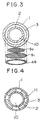
- FIG. 3 is a cross sectional view of the nozzle top of a laser irradiation nozzle according to an embodiment of the present invention;
- FIG. 4 is a cross sectional view of the nozzle top of a laser irradiation nozzle according to another embodiment of the present invention;
- FIG. 5 is a cross sectional view showing a half of the laser emission unit of a laser irradiation nozzle according to an embodiment of the present invention;
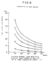
- FIG. 6 is a graph showing the evaluation of bead shapes obtained in the Examples of laser welding;
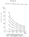
- FIG. 7 is a graph showing the evaluation of adhesion states of metal oxides observed in the Examples of laser welding;
- FIG. 8 is a graph showing the evaluation of surface states of metal oxides observed in the Examples of laser welding;
- FIG. 9 is a graph showing the evaluation of nozzle clogging observed in the Examples of laser welding;
- FIG. 10 is a diagram showing the relation between the nozzle area ratio n and the distance h from the nozzle top to the work for the laser irradiation nozzles according to the present invention;
- FIG. 11 is showing the state of the metal surface of the specimen obtained by laser welding according to an Example;
- FIG. 12 is showing the state of the metal surface of the specimen obtained by laser welding according to an Example;
- FIG. 13 is showing the state of the metal surface of the specimen obtained by laser welding according to an Example;
- FIG. 14 is showing the state of the metal surface of the specimen obtained by laser welding according to an Example;
- FIG. 15 is showing the state of the metal surface of the specimen obtained by laser welding according to an Example;
- FIG. 16 is showing the state of the metal surface of the specimen obtained by laser welding according to an Example;
- FIG. 17 is showing the state of the metal surface of the specimen obtained be laser welding according to an Example;
- FIG. 18 is showing the state of the metal surface of the specimen obtained by laser welding according to an Example;
- FIG. 19 is showing the state of the metal surface of the specimen obtained by laser welding according to an Example;
- FIG. 20 is showing the state of the metal surface of the specimen obtained by laser welding according to Comparative Example 2;
- FIG. 21 is showing the state of the metal surface of the specimen obtained by laser welding according to Comparative Example 3;
- FIG. 22 is showing the state of the metal surface of the specimen obtained by laser welding according to Comparative Example 1;
- FIG. 23 is an explanatory figure showing the entire structure of the laser apparatus according to an embodiment of the present invention;
- FIG. 24 is an explanatory figure showing the structure of the nozzle top of an irradiation nozzle of a center gas type used in Comparative Example 2; and FIG. 25 is an explanatory figure showing the structure of the nozzle top of an irradiation nozzle of a side gas type used in Comparative Example 3.
- Referring to FIG. 23, the entire structure of the laser apparatus according to the present invention is explained below.
- A
laser power source 17 supplied with an AC of 400 V supplies a predetermined electric power to alaser head 18, and the laser beam having generated from thelaser head 18 at a predetermined frequency is introduced to a laser emission unit (laser irradiation nozzle) 20 via an optical fiber F. - The
laser power source 17 and thelaser head 18 are chilled by circulating a coolant providing from a cooler 21 to prevent the laser power source and the laser head from being overheated. - The movement of the irradiating
unit 20 along the XYZ directions and the θ angular direction is controlled by a drivingstage 22 and anarm 23. The drivingstage 22 and thearm 23 are controlled by a control system comprising adisplay 24, alaser controller 25, aprogramming box 26, and arobot control unit 27. - Furthermore, an assist gas (Ar gas)
source 28 and anair compressor 30 are connected to the top of thelaser emission unit 20. The structure of the top of theirradiation unit 20, i.e., the structure of the irradiation nozzle, is described in further detail below referring to Figs. 1 to 5. - In FIG. 5 is shown a laser irradiation nozzle according to an Example, having a structure characteristic to the present invention. The
laser emission unit 20 is connected to the top of the optical fiber F. - The present unit includes two
internal lenses cylindrical shell 5, and acylinder top 6 being joined to thecylindrical shell 5. Further to thecylinder top 6 is provided a taperednozzle portion 8. As shown in Figs. 1 and 2, thenozzle portion 8 comprises a conical outside nozzle 1 and aninside nozzle 2 being arranged concentrically, to provide a double layered trapezoid structure, i.e., a cone having its head cut with a plane at a certain distance from the top. In this manner, an assistgas outlet 3 for ejecting the assist gas (against the surface of the weld specimen) can be opened between the outside nozzle 1 and theinside nozzle 2. Furthermore, alaser emission outlet 10 is opened at the top of theinside nozzle 2 to emit therefrom a laser beam concentrated by thelenses - Among the two nozzles constituting the whole double layered concentrical trapezoid nozzle, the
inside nozzle 2 has an inner shape being machined into a hemispherical cone, such that the inner side may not interfere with the path of the laser beam. On the other hand, the outside nozzle (illustrated schematically in Fig 1) is shaped into a cone having its outer plane being tilted at an angle of θ with respect to the center axis thereof, and an apex of the cone corresponding to the focal point of the laser beam. - A
gas flow path 12 which connects the assist gas source with the assistgas outlet 3 via agas introduction portion 16 is defined between the outside nozzle 1 and theinside nozzle 2. - Furthermore, a transparent
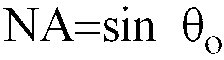
protective glass 9 is inserted between thelaser emission outlet 10 thelense 4b. - The laser emission unit as described above was used in an experimental welding. A laser apparatus equipped with a pulsed YAG laser (wavelength: 1.06 µm) operating in multi-mode at an average power output of 480 W and at a repetition of 8 pps was used in the experiment. An optical system having a focal length f of 120 mm, a converging angle of θo of 14.5° (where, numerical aperture
- The specimen used in the welding was prepared by welding two lap-jointed JIS A5052 sheets, each 100 mm in length, 30 mm in width, and 1.0 mm in thickness. The welding was conducted at a welding rate of 50 cm/min for a length of 20 mm, using argon (Ar) as the assist gas.
- In the present invention, k=1.05 was selected for the equation (3). The distance between the laser beam focal plane of image-formation side and the top of the nozzle h was changed, and the nozzle area ratio η (%) was varied accordingly for each of the changed h values to observe the influence on the shape of weld beads with the changing parameters. More specifically, the value h was varied in 6 levels, i.e., 5, 10, 20, 30, 40, and 50 mm. The η (%) was varied for each of the h values in 5 levels to prepare 30 types in total of laser irradiation nozzles. The rate of the assist gas flow was varied in the range of from 0 to 40 l/min.
- The weld beads were evaluated for the following items: external appearance of the bead shape such as disturbed bead shape; adhesion of the metal oxide to the surface of the specimen; oxidation degree of the surface of the specimen; clogging of the top of the laser irradiation nozzle due to the formation of sputters and fume; and the influence on the weld depth.
- The evaluation results obtained under an assist gas flow rate of 20 l/min are shown below.
- Each of the weld beads obtained under various conditions was evaluated for the external appearance such as whether there is observed a disturbance in bead shape. The results are summarized in FIG. 6.
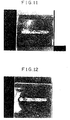
- In FIG. 6, the conditions marked with X correspond to unfavorable ones under which disordering of molten metal due to excessively high flow rate, i.e., humping beads, and undercuts of the beads are observed; the external appearance of such beads can be observed in FIG. 11.
- Those marked with △ are acceptable conditions, under which some undercuts may be observed on the bead, but rather, under which a somewhat humping bead appearance; this can be observed in FIG. 12. Those marked with ○ are favorable conditions under which favorable bead shapes can be observed as shown in the photograph of FIG. 13.
- The results for the evaluation of the adhesion of metal oxides under each of the welding conditions enumerated above are summarized in FIG. 7. The conditions marked with X correspond to unfavorable ones under which the adhesion of a considerable amount of black colored metal oxides over a wide area is observed: the external appearance of such beads can be observed in the photograph given in FIG. 14. Those marked with △ are acceptable conditions, under which beads having metal oxides adhered over a reduced area as compared to those observed under conditions marked with X are obtained; this can be observed in the photograph of FIG. 15. Those marked with ○ are favorable conditions under which favorable bead appearances having little adhesion of metal oxides can be observed, as shown in the photograph of FIG. 16.
- The evaluation results under each of the welding conditions are summarized in FIG. 8. The conditions marked with X correspond to unfavorable ones under which a considerable amount of white colored surface oxidized region is observed to spread over a wide area; the external appearance of such beads can be observed in the photograph given in FIG. 17. Those marked with △ are acceptable conditions, under which beads having an oxidized region being spread over a reduced area as compared to those observed under conditions marked with X are obtained; this can be observed in the photograph of FIG. 18. Those marked with ○ are favorable conditions under which favorable bead appearances having little formation of oxidized are obtained, as shown in the photograph of FIG. 17.
- irradiation nozzleThe evaluation results under each of the welding conditions are summarized in FIG. 9. The conditions marked with X correspond to unfavorable ones under which the weld sputters and fume are observed to adhere to the top of the laser irradiation nozzle; under such conditions. the top of the nozzle suffer inconveniences such as clogging due to the sputters and the like, which leads to a disturbed assist gas ejection, or, even worse, to a complete cease of the assist gas flow. Those marked with ○ are favorable conditions under which no adhesion of weld sputters and fume is observed.
- The influence on the weld depth was evaluated under each of the weld conditions above, but no influence was observed on the penetration depth under any of the conditions.
- In FIG. 10 is shown the total evaluation for the results obtained herein before. The region I is defined by:


- Furthermore, the flow rate of the assist gas was varied for each of the welding conditions above. It was confirmed that the regions defined above can be conducted without any problem by setting the rate to 10 l/min or higher.
- Similar results were obtained on nozzles having a constant diameter rout for the inner diameter of the outside nozzle but with inserts made of differing materials such as a metal, a ceramics, and a heat resistant plastic, being incorporated between the inside and the
outside nozzles 1 and 2, as illustrated in FIG. 4. - The result obtained through a welding experiment using a coaxial nozzle having a nozzle top distance h of 5 mm is shown in the photograph of FIG. 22. The flow rate of the assist gas was varied in the same manner as in the Example described above, but only an unfavorable external appearance was observed for all of the cases with a considerable amount of metal oxides being adhered over a large area of the weld surface.
- A welding experiment under an assist gas was conducted using a nozzle of a center gas type, as illustrated in FIG. 24. The result is shown in the photograph of FIG. 20.
- FIG. 20 reads that even though the flow rate of the assist gas is varied in the same manner as in the Example described above, an unfavorable external appearance only can be observed for all of the cases with a considerable amount of metal oxides being adhered over a large area of the weld surface.
- A welding experiment under an assist gas was conducted using a nozzle of a side gas type, as illustrated in FIG. 25. The result is shown in the photograph of FIG. 21.
- It can be seen that in the present comparative example again, an unfavorable external appearance only can be observed for all of the cases with a considerable amount of metal oxides being adhered over a large area of the weld surface, even though the flow rate of the assist gas is varied in the same manner as in the Example described above.
- While the invention has been described in detail and with reference to specific examples thereof. it will be apparent to one skilled in the art that various changes and modifications can be made therein without departing from the scope thereof.
Claims (6)
- A laser apparatus having focusing means (4) to focus a laser beam to a predetermined focal plane and a laser irradiation nozzle comprising:
a conical outside nozzle (1) and a conical inside nozzle (2) for irradiating the laser beam, the nozzles (1,2) being arranged concentrically to provide a concentric ring-shaped nozzle top having, between said inside (2) and outside nozzles (1), an assist gas outlet (3) for ejecting therefrom an assist gas, wherein the outer surface of the inside nozzle (2) is tilted from the laser beam axis at a tilt angle θ (deg) defined by


- A laser irradiation nozzle having focusing means (4) to focus a laser beam to a predetermined focal plan comprising:
a conical outside nozzle (1) and a conical inside nozzle (2) for irradiating the laser beam, the nozzles (1,2) being arranged concentrically to provide a concentric ring-shaped nozzle top having, between said inside (2) and outside nozzles (1), an assist gas outlet (3) for ejecting therefrom an assist gas, wherein the outer surface of the inside nozzle (2) is tilted from the laser beam axis at a tilt angle θ (deg) defined by


- An apparatus as claimed in claim 1 or 2, wherein the laser irradiation nozzle is shaped such that the ratio η (%) satisfies the following relations

- An apparatus as claimed in claim 3, wherein the laser irradiation nozzle is shaped such that the ratio η (%) satisfies the following relations

- An apparatus as claimed in any one of the preceding claims, wherein the value k is in the range of from 1.05 to 1.50.
- A method of operating an apparatus as claimed in any one of the preceding claims wherein the assist gas is caused to issue from the assist gas outlet (3) at a flow rate of 10 1/min or higher.
Applications Claiming Priority (2)
| Application Number | Priority Date | Filing Date | Title |
|---|---|---|---|
| JP8981492 | 1992-03-13 | ||
| JP89814/92 | 1992-03-13 |
Publications (2)
| Publication Number | Publication Date |
|---|---|
| EP0560637A1 EP0560637A1 (en) | 1993-09-15 |
| EP0560637B1 true EP0560637B1 (en) | 1996-06-26 |
Family
ID=13981210
Family Applications (1)
| Application Number | Title | Priority Date | Filing Date |
|---|---|---|---|
| EP93301950A Expired - Lifetime EP0560637B1 (en) | 1992-03-13 | 1993-03-15 | Laser irradiation nozzle and laser apparatus using the same |
Country Status (5)
| Country | Link |
|---|---|
| US (1) | US5293023A (en) |
| EP (1) | EP0560637B1 (en) |
| KR (1) | KR930019332A (en) |
| CA (1) | CA2091512A1 (en) |
| DE (1) | DE69303303T2 (en) |
Families Citing this family (33)
| Publication number | Priority date | Publication date | Assignee | Title |
|---|---|---|---|---|
| JPH06210481A (en) * | 1993-01-14 | 1994-08-02 | Fanuc Ltd | Laser beam machining control method |
| JP3237441B2 (en) * | 1995-02-28 | 2001-12-10 | 三菱電機株式会社 | Laser processing equipment |
| US5637245A (en) * | 1995-04-13 | 1997-06-10 | Vernay Laboratories, Inc. | Method and apparatus for minimizing degradation of equipment in a laser cleaning technique |
| US6060686A (en) * | 1996-10-15 | 2000-05-09 | General Electric Company | Underwater laser welding nozzle |
| US6437285B1 (en) | 1998-06-02 | 2002-08-20 | General Lasertronics Corporation | Method and apparatus for treating interior cylindrical surfaces and ablating surface material thereon |
| US6822187B1 (en) * | 1998-09-09 | 2004-11-23 | Gsi Lumonics Corporation | Robotically operated laser head |
| KR100300600B1 (en) * | 1998-12-18 | 2001-11-22 | 구자홍 | Glass cutting device using laser beam |
| DE19905739A1 (en) * | 1999-02-11 | 2000-08-17 | Linde Tech Gase Gmbh | Method and device for laser material processing with coaxial gas flow |
| DE29922544U1 (en) * | 1999-12-22 | 2001-05-03 | KUKA Schweissanlagen GmbH, 86165 Augsburg | Blowing device for a laser device |
| JP3476441B2 (en) * | 2001-04-11 | 2003-12-10 | ファナック株式会社 | Laser processing nozzle |
| US7800014B2 (en) | 2004-01-09 | 2010-09-21 | General Lasertronics Corporation | Color sensing for laser decoating |
| US7633033B2 (en) | 2004-01-09 | 2009-12-15 | General Lasertronics Corporation | Color sensing for laser decoating |
| DE102004049115A1 (en) * | 2004-10-07 | 2006-04-27 | Johnson Controls Gmbh | Welded structure, in particular of seat components |
| FR2891483B1 (en) * | 2005-10-05 | 2009-05-15 | Commissariat Energie Atomique | METHOD AND INSTALLATION OF LASER CUTTING / WELDING |
| FR2892328B1 (en) * | 2005-10-21 | 2009-05-08 | Air Liquide | LASER BEAM WELDING METHOD WITH CONTROL OF METAL VAPOR CAPILLARY FORMATION |
| EP1977193B1 (en) * | 2005-12-16 | 2015-09-02 | TRUMPF Werkzeugmaschinen GmbH + Co. KG | Insulator for a sensor arrangement of a laser machining tool |
| TW200726566A (en) * | 2006-01-10 | 2007-07-16 | Li Bing Huan | Laser processing machine |
| US7456370B2 (en) * | 2006-01-30 | 2008-11-25 | Honeywell International Inc. | Welding shield and flexible skirt for automated welding |
| US8536483B2 (en) * | 2007-03-22 | 2013-09-17 | General Lasertronics Corporation | Methods for stripping and modifying surfaces with laser-induced ablation |
| WO2009005840A1 (en) * | 2007-07-05 | 2009-01-08 | General Lasertronics Corporation | Aperture adapters for laser-based coating removal end-effector |
| JP5418588B2 (en) * | 2009-03-31 | 2014-02-19 | トヨタ自動車株式会社 | Laser processing equipment |
| US10112257B1 (en) | 2010-07-09 | 2018-10-30 | General Lasertronics Corporation | Coating ablating apparatus with coating removal detection |
| US9895771B2 (en) | 2012-02-28 | 2018-02-20 | General Lasertronics Corporation | Laser ablation for the environmentally beneficial removal of surface coatings |
| DE112012006616T5 (en) * | 2012-06-28 | 2015-04-23 | Mitsubishi Electric Corporation | Fiber laser beam machine |
| DE102012217082B4 (en) * | 2012-09-21 | 2016-06-16 | Trumpf Laser Gmbh | Laser processing head with a ring nozzle |
| US10086597B2 (en) | 2014-01-21 | 2018-10-02 | General Lasertronics Corporation | Laser film debonding method |
| US20150225845A1 (en) * | 2014-02-12 | 2015-08-13 | Electronics And Telecommunications Research Institute | Method for forming metal oxide thin film and device for printing metal oxide thin film |
| JP6124425B1 (en) * | 2015-10-26 | 2017-05-10 | 株式会社日本製鋼所 | Laser processing device rectifier and laser processing device |
| JPWO2018216275A1 (en) * | 2017-05-24 | 2020-04-02 | パナソニックIpマネジメント株式会社 | Capacitance type height sensor, laser processing nozzle using the same, and laser processing apparatus |
| CN109317818A (en) * | 2018-10-10 | 2019-02-12 | 南京理工大学 | Gas shielded laser welding system and its working method |
| JP7028820B6 (en) * | 2019-03-18 | 2023-12-19 | ファナック株式会社 | Laser processing method for cutting workpieces |
| EP3892414A1 (en) * | 2020-04-06 | 2021-10-13 | Bystronic Laser AG | Laser processing machine |
| DE112021003105T5 (en) * | 2020-06-03 | 2023-04-06 | Fanuc Corporation | laser device |
Family Cites Families (4)
| Publication number | Priority date | Publication date | Assignee | Title |
|---|---|---|---|---|
| US4774392A (en) * | 1985-04-16 | 1988-09-27 | Amada Engineering & Service Co., Inc. | Laser cutting method for high chromium steel and a device to carry out that method |
| DE3637568A1 (en) * | 1986-11-04 | 1988-05-05 | Trumpf Gmbh & Co | Laser machine tool |
| FR2667805B1 (en) * | 1990-10-16 | 1993-01-22 | Aerospatiale | LASER SURFACE TREATMENT NOZZLE WITH POWDER SUPPLY. |
| CA2064513A1 (en) * | 1991-04-01 | 1992-10-02 | Hiroyuki Okuyama | Laser output unit |
-
1993
- 1993-03-12 CA CA002091512A patent/CA2091512A1/en not_active Abandoned
- 1993-03-12 KR KR1019930003722A patent/KR930019332A/en not_active Ceased
- 1993-03-12 US US07/030,537 patent/US5293023A/en not_active Expired - Fee Related
- 1993-03-15 EP EP93301950A patent/EP0560637B1/en not_active Expired - Lifetime
- 1993-03-15 DE DE69303303T patent/DE69303303T2/en not_active Expired - Fee Related
Also Published As
| Publication number | Publication date |
|---|---|
| EP0560637A1 (en) | 1993-09-15 |
| DE69303303D1 (en) | 1996-08-01 |
| DE69303303T2 (en) | 1996-10-31 |
| US5293023A (en) | 1994-03-08 |
| CA2091512A1 (en) | 1993-09-14 |
| KR930019332A (en) | 1993-10-18 |
Similar Documents
| Publication | Publication Date | Title |
|---|---|---|
| US5293023A (en) | Laser irradiation nozzle and laser apparatus using the same | |
| EP3459675B1 (en) | Laser cutting and machining method for plated steel plate, laser cut-and-machined product, laser machining head | |
| JP3159593B2 (en) | Laser processing method and apparatus | |
| JP3385361B2 (en) | Laser welding method and laser welding apparatus | |
| EP0527229B1 (en) | Laser and laser welding method | |
| US6727459B1 (en) | Method for metal deposition on an edge | |
| US7015417B2 (en) | Workpiece welding process | |
| Sun et al. | Comparative evaluation of tungsten inert gas and laser welding of AZ31 magnesium alloy | |
| JP3392683B2 (en) | Laser processing head | |
| KR102534335B1 (en) | Method for producing a pre-coated metal sheet, with removal of the coating by means of an inclined laser beam, and corresponding metal sheet | |
| US20080116175A1 (en) | Laser welding process with improved penetration | |
| GB2191434A (en) | Methods of cutting metallic workpieces by laser | |
| EP4731375A1 (en) | System and method for processing or joining materials and their application | |
| JP2003164983A (en) | Welding method for metal parts | |
| Brandt et al. | Laser cladding with a pulsed Nd: YAG laser and optical fibers | |
| JPH11267876A (en) | Laser processing nozzle | |
| WO1997004914A1 (en) | Pulsed laser cladding arrangement | |
| EP3785843B1 (en) | Laser-arc hybrid welding apparatus | |
| JP2865543B2 (en) | Laser processing head | |
| JP4575640B2 (en) | Laser welding method and laser welding apparatus | |
| JPS61229491A (en) | Processing head for laser welding | |
| JPH067985A (en) | Laser beam irradiating nozzle and laser beam equipment using the same | |
| Üstündağ et al. | Influence of an external applied AC magnetic field on the melt pool dynamics at high-power laser beam welding | |
| JPH0819886A (en) | Laser welding nozzle | |
| JPH0428883A (en) | Method and device for lining bearing back plate with white metal |
Legal Events
| Date | Code | Title | Description |
|---|---|---|---|
| PUAI | Public reference made under article 153(3) epc to a published international application that has entered the european phase |
Free format text: ORIGINAL CODE: 0009012 |
|
| AK | Designated contracting states |
Kind code of ref document: A1 Designated state(s): CH DE FR GB IT LI NL |
|
| 17P | Request for examination filed |
Effective date: 19940307 |
|
| R17P | Request for examination filed (corrected) |
Effective date: 19940304 |
|
| 17Q | First examination report despatched |
Effective date: 19950221 |
|
| GRAH | Despatch of communication of intention to grant a patent |
Free format text: ORIGINAL CODE: EPIDOS IGRA |
|
| GRAH | Despatch of communication of intention to grant a patent |
Free format text: ORIGINAL CODE: EPIDOS IGRA |
|
| GRAA | (expected) grant |
Free format text: ORIGINAL CODE: 0009210 |
|
| AK | Designated contracting states |
Kind code of ref document: B1 Designated state(s): CH DE FR GB IT LI NL |
|
| PG25 | Lapsed in a contracting state [announced via postgrant information from national office to epo] |
Ref country code: LI Effective date: 19960626 Ref country code: CH Effective date: 19960626 |
|
| ET | Fr: translation filed | ||
| ITF | It: translation for a ep patent filed | ||
| REF | Corresponds to: |
Ref document number: 69303303 Country of ref document: DE Date of ref document: 19960801 |
|
| REG | Reference to a national code |
Ref country code: CH Ref legal event code: PL |
|
| PGFP | Annual fee paid to national office [announced via postgrant information from national office to epo] |
Ref country code: GB Payment date: 19970306 Year of fee payment: 5 |
|
| PGFP | Annual fee paid to national office [announced via postgrant information from national office to epo] |
Ref country code: FR Payment date: 19970313 Year of fee payment: 5 |
|
| PGFP | Annual fee paid to national office [announced via postgrant information from national office to epo] |
Ref country code: DE Payment date: 19970321 Year of fee payment: 5 |
|
| PGFP | Annual fee paid to national office [announced via postgrant information from national office to epo] |
Ref country code: NL Payment date: 19970327 Year of fee payment: 5 |
|
| PLBE | No opposition filed within time limit |
Free format text: ORIGINAL CODE: 0009261 |
|
| STAA | Information on the status of an ep patent application or granted ep patent |
Free format text: STATUS: NO OPPOSITION FILED WITHIN TIME LIMIT |
|
| 26N | No opposition filed | ||
| PG25 | Lapsed in a contracting state [announced via postgrant information from national office to epo] |
Ref country code: GB Free format text: LAPSE BECAUSE OF NON-PAYMENT OF DUE FEES Effective date: 19980315 |
|
| PG25 | Lapsed in a contracting state [announced via postgrant information from national office to epo] |
Ref country code: FR Free format text: THE PATENT HAS BEEN ANNULLED BY A DECISION OF A NATIONAL AUTHORITY Effective date: 19980331 |
|
| PG25 | Lapsed in a contracting state [announced via postgrant information from national office to epo] |
Ref country code: NL Free format text: LAPSE BECAUSE OF NON-PAYMENT OF DUE FEES Effective date: 19981001 |
|
| GBPC | Gb: european patent ceased through non-payment of renewal fee |
Effective date: 19980315 |
|
| NLV4 | Nl: lapsed or anulled due to non-payment of the annual fee |
Effective date: 19981001 |
|
| PG25 | Lapsed in a contracting state [announced via postgrant information from national office to epo] |
Ref country code: DE Free format text: LAPSE BECAUSE OF NON-PAYMENT OF DUE FEES Effective date: 19981201 |
|
| REG | Reference to a national code |
Ref country code: FR Ref legal event code: ST |
|
| PG25 | Lapsed in a contracting state [announced via postgrant information from national office to epo] |
Ref country code: IT Free format text: LAPSE BECAUSE OF NON-PAYMENT OF DUE FEES;WARNING: LAPSES OF ITALIAN PATENTS WITH EFFECTIVE DATE BEFORE 2007 MAY HAVE OCCURRED AT ANY TIME BEFORE 2007. THE CORRECT EFFECTIVE DATE MAY BE DIFFERENT FROM THE ONE RECORDED. Effective date: 20050315 |