EP0558283B1 - Improvements in self-energising disc brakes - Google Patents
Improvements in self-energising disc brakes Download PDFInfo
- Publication number
- EP0558283B1 EP0558283B1 EP19930301346 EP93301346A EP0558283B1 EP 0558283 B1 EP0558283 B1 EP 0558283B1 EP 19930301346 EP19930301346 EP 19930301346 EP 93301346 A EP93301346 A EP 93301346A EP 0558283 B1 EP0558283 B1 EP 0558283B1
- Authority
- EP
- European Patent Office
- Prior art keywords
- pressure plates
- brake
- spring
- drag
- discs
- Prior art date
- Legal status (The legal status is an assumption and is not a legal conclusion. Google has not performed a legal analysis and makes no representation as to the accuracy of the status listed.)
- Expired - Lifetime
Links
Images



Classifications
-
- F—MECHANICAL ENGINEERING; LIGHTING; HEATING; WEAPONS; BLASTING
- F16—ENGINEERING ELEMENTS AND UNITS; GENERAL MEASURES FOR PRODUCING AND MAINTAINING EFFECTIVE FUNCTIONING OF MACHINES OR INSTALLATIONS; THERMAL INSULATION IN GENERAL
- F16D—COUPLINGS FOR TRANSMITTING ROTATION; CLUTCHES; BRAKES
- F16D55/00—Brakes with substantially-radial braking surfaces pressed together in axial direction, e.g. disc brakes
- F16D55/02—Brakes with substantially-radial braking surfaces pressed together in axial direction, e.g. disc brakes with axially-movable discs or pads pressed against axially-located rotating members
- F16D55/04—Brakes with substantially-radial braking surfaces pressed together in axial direction, e.g. disc brakes with axially-movable discs or pads pressed against axially-located rotating members by moving discs or pads away from one another against radial walls of drums or cylinders
- F16D55/14—Brakes with substantially-radial braking surfaces pressed together in axial direction, e.g. disc brakes with axially-movable discs or pads pressed against axially-located rotating members by moving discs or pads away from one another against radial walls of drums or cylinders with self-tightening action, e.g. by means of coacting helical surfaces or balls and inclined surfaces
-
- F—MECHANICAL ENGINEERING; LIGHTING; HEATING; WEAPONS; BLASTING
- F16—ENGINEERING ELEMENTS AND UNITS; GENERAL MEASURES FOR PRODUCING AND MAINTAINING EFFECTIVE FUNCTIONING OF MACHINES OR INSTALLATIONS; THERMAL INSULATION IN GENERAL
- F16D—COUPLINGS FOR TRANSMITTING ROTATION; CLUTCHES; BRAKES
- F16D2125/00—Components of actuators
- F16D2125/18—Mechanical mechanisms
- F16D2125/20—Mechanical mechanisms converting rotation to linear movement or vice versa
- F16D2125/34—Mechanical mechanisms converting rotation to linear movement or vice versa acting in the direction of the axis of rotation
- F16D2125/36—Helical cams, Ball-rotating ramps
-
- F—MECHANICAL ENGINEERING; LIGHTING; HEATING; WEAPONS; BLASTING
- F16—ENGINEERING ELEMENTS AND UNITS; GENERAL MEASURES FOR PRODUCING AND MAINTAINING EFFECTIVE FUNCTIONING OF MACHINES OR INSTALLATIONS; THERMAL INSULATION IN GENERAL
- F16D—COUPLINGS FOR TRANSMITTING ROTATION; CLUTCHES; BRAKES
- F16D2125/00—Components of actuators
- F16D2125/18—Mechanical mechanisms
- F16D2125/58—Mechanical mechanisms transmitting linear movement
- F16D2125/66—Wedges
Definitions
- This invention relates to self-energising disc brakes of the kind known for example from DE-U-9105349 in which rotatable friction discs provided with linings of friction material are adapted to be brought into engagement with spaced opposed braking surfaces in housing by pressure plates located between the friction discs and centered by stationary pilot lugs, balls or rollers are located in co-operating oppositely inclined recesses in the adjacent faces of the pressure plates, and the application of the brake is initiated by moving the pressure plates angularly in opposite directions, the pressure plates then moving apart, due to the tendency for the balls or rollers to ride up ramps defined by the recesses, and into engagement with the friction discs, which, in turn, are urged into engagement with the braking surfaces, and the pressure plates are carried round with the friction discs in one direction of forward or reverse rotation until one pressure plate is arrested by the engagement of a lug on that plate with a drag-taking stop abutment in the housing, the continued angular movement of the other pressure plate providing a servo action for that
- Self-energising brake discs of the kind set forth may be dry or they may be of the liquid cooled type, and such brakes are commonly used in tractors and like vehicles and are hereinafter called brakes of the kind set forth.
- actuating means comprising an assembly of the two pressure plates and the balls or rollers has a tendency to adopt a substantially central position within the housing in an off position of brake.
- an audible "clonk” may result, the sound caused by the brake actuator assembly being angularly accelerated such that the lug on the respective pressure plate impacts against the drag-taking stop abutment.
- the amplitude of this sound is a function of the magnitude of the clearance or gap, rotational speed, the rate of application of the brake, and the mass of the actuator. The amplitude of "clonk” is therefore highly variable.
- a self-energising disc brake of the kind set forth drag generating means are provided to generate a drag force in an off position of brake of a magnitude sufficient to carry the pressure plates round with the discs through an angular distance sufficient for the lug on the said one plate to cooperate with the drag-taking stop abutment for a given direction of disc rotation.
- the useful drag in the off position of brake is controlled to drive the actuator gently into abutment contact from low rotational speed and then maintain the gap or clearance at zero for that direction of disc rotation.
- the drag generating means may act to urge relatively rotatable braking members into light engagement in order to generate sufficient drag to carry the pressure plates round with the disc.
- the drag generating means comprises at least one spring arranged to apply an axially directed force to the braking members. Under a light spring force, therefore, a small clamping pressure can be exerted on two or more of the braking faces. This will generate a drag force and rotate the actuator into torque abutment engagement in either forward or reverse directions of rotation, for subsequent braking.
- the clamping pressure is adapted to be held at a minimum value necessary to rotate the actuator and so avoid wear and heat generation.
- a spring acts between rotatable discs on opposite sides of the pressure plates.
- the spring may comprise a compression spring which surrounds and rotates with a shaft to be braked and acts between the two rotatable discs with and between which the pressure plates cooperate.
- at least one light tension spring co-operates between the two plates to urge them towards each other.
- At least one light spring may act on or between a pair of friction discs.
- at least one spring comprising a tension spring, acts to urge a pair of stators on opposite sides of the pressure plates towards each other, and the tension spring is disposed outside the peripheral edge of the rotors and the pressure plates.
- the tension spring acts to urge towards each other a pair of rotors on opposite sides of a stator.
- the spring comprises a compression spring housed in one end of the housing and acting on an adjacent stack of friction members through the outer most stator of the stack.
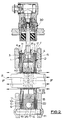
- the brake illustrated in Figures 1 and 2 of the drawings is of a conventional spreading type in which two stacks 1 and 2 of friction discs are located between spaced opposed braking surfaces 3,4 in opposite ends of a housing 5.
- the stack 1 of discs comprises two rotatable friction discs 6, 7 constituting rotors and which are slidably splined on a rotatable shaft 8, a non-rotatable discs 9 constituting a stator which is keyed to the housing against rotation by means of at least one transverse pin 11, and a disc 10 which is keyed to the pressure plate 16.
- the other stack 2 of discs comprises inner and outer rotors 12, 13, also slidably splined to the shaft, and a disc 14 disposed between the two rotors and keyed to the pressure plate 17.
- An actuator assembly 15 is located in the housing between the innermost rotors 7, 12 of the respective stacks 1 and 2.
- the actuator assembly 15 comprises pressure plates 16, 17 which are centered by angularly spaced stationary pilots comprising transverse pins 18, 19, 20, 21.
- Balls 22 are located in cooperating oppositely inclined recesses in the adjacent faces of the pressure plates 16, 17 and angularly spaced tension springs 23 act to urge the two pressure plates 16, 17 towards each other with the balls 22 located in the recesses at the inner ends of ramps defined by the sides of the recesses.
- the application of the brake is initiated by moving the pressure plates 16, 17 angularly in opposite directions which causes the pressure plates 16, 17 to move axially relatively away from each other due to the tendency for the balls 22 to ride up the ramps defined by the sides of the recesses.
- the pressure plates 16, 17 are then carried round with the rotors 6, 7, 12, 13 until one is arrested by the engagement of a lug 25 or 26, on a respective plate 16, 17 with a drag-taking abutment constituted by the pin 18 or the pin 19, according to the direction of rotation of the shaft 8.
- Continued angular movement of the other plate with the rotors 6, 7, 12, 13 provides a servo-action, which is enhanced to a multi-servo action by the disc 10 or 14 also being carried round with the servo pressure plate.
- Angular movement of the pressure plates 16, 17 in opposite directions is initiated by means of an hydraulic actuator 30 of known construction having a wedge 31 which separates adjacent ends of the two pressure plates 16, 17 as the wedge is displaced radially in an inward direction.
- a compression spring 40 surrounding the shaft 8 acts at opposite ends against the rotors 7 and 12 to apply a light force to these rotors in order to apply a small clamping force to the discs of the two stacks 1 and 2 the compression spring 40 rotates with the shaft 8 and with the rotors 7 and 12.
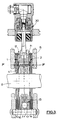
- the compression spring 40 is replaced by a tension spring 41 which couples the two rotors 7 and 12 together and urges them towards each other.
- the force F from the spring 41 generates a small useful drag between faces at g and h between the rotors 7 and 12 and the pressure plates 16 and 17.
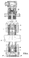
- a light tension spring 42 acts between intermediate discs 10, 14 of the two stacks 1, 2 to generate small useful drag between the faces at j , k , l , m , when the discs 10, 14 are keyed to the respective pressure plates 16 and 17.
- a plurality of light tension springs may be incorporated with the springs lying outside the peripheral edges of the pressure plates 16, 17.
- Small useful drag is provided between faces at n , o , p , r , s , t .
- a plurality of compression springs similar to the spring 46 may be provided in the inner wall of the housing at angularly space positions.
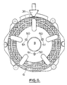
- each spring 50 is of "Figure 8" configuration and is passed through axially aligned openings 51, 52 in the two rotors so that they are urged axially towards each other with a light force in order to generate a useful drag when the shaft 8 is rotatably in a "brake-off" position.
Landscapes
- Engineering & Computer Science (AREA)
- General Engineering & Computer Science (AREA)
- Mechanical Engineering (AREA)
- Braking Arrangements (AREA)
Description
- This invention relates to self-energising disc brakes of the kind known for example from DE-U-9105349 in which rotatable friction discs provided with linings of friction material are adapted to be brought into engagement with spaced opposed braking surfaces in housing by pressure plates located between the friction discs and centered by stationary pilot lugs, balls or rollers are located in co-operating oppositely inclined recesses in the adjacent faces of the pressure plates, and the application of the brake is initiated by moving the pressure plates angularly in opposite directions, the pressure plates then moving apart, due to the tendency for the balls or rollers to ride up ramps defined by the recesses, and into engagement with the friction discs, which, in turn, are urged into engagement with the braking surfaces, and the pressure plates are carried round with the friction discs in one direction of forward or reverse rotation until one pressure plate is arrested by the engagement of a lug on that plate with a drag-taking stop abutment in the housing, the continued angular movement of the other pressure plate providing a servo action for that direction of disc rotation.
- Self-energising brake discs of the kind set forth may be dry or they may be of the liquid cooled type, and such brakes are commonly used in tractors and like vehicles and are hereinafter called brakes of the kind set forth.
- In a brake of the kind set forth actuating means comprising an assembly of the two pressure plates and the balls or rollers has a tendency to adopt a substantially central position within the housing in an off position of brake.
- This results in a clearance or gap being present between the drag-taking stop abutment and the lug on the pressure plate which is adapted to co-operate with it when the brake is applied. Centralisation is most likely to occur when parasitic drag between the braking faces is low, a condition designed into brakes of the kind set forth in order to minimise power loss at low temperature. The large running clearances between friction discs and the pressure plates reduce parasitic drag almost to zero at high temperatures when, in liquid cooled brakes, the viscosity of the liquid is low. The clearance or gap between the drag-taking stop abutment and each respective lug is a function of tolerances, running clearances and lining wear and it increases with further brake adjustment to take account of these factors.
- If the brake is actuated and the linings engage and produce rotation of the actuator from a substantially central position, an audible "clonk" may result, the sound caused by the brake actuator assembly being angularly accelerated such that the lug on the respective pressure plate impacts against the drag-taking stop abutment. The amplitude of this sound is a function of the magnitude of the clearance or gap, rotational speed, the rate of application of the brake, and the mass of the actuator. The amplitude of "clonk" is therefore highly variable.
- According to our invention in a self-energising disc brake of the kind set forth drag generating means are provided to generate a drag force in an off position of brake of a magnitude sufficient to carry the pressure plates round with the discs through an angular distance sufficient for the lug on the said one plate to cooperate with the drag-taking stop abutment for a given direction of disc rotation.
- This therefore eliminates the clearance between the lug and the drag-taking stop abutment for either the forward or reverse directions of disc rotation. Since no clearance has to be taken up when the brake is applied, any tendency for sound to be emitted during brake operation due to the engagement between the lug and the drag-taking abutment is thus eliminated.
- The useful drag in the off position of brake is controlled to drive the actuator gently into abutment contact from low rotational speed and then maintain the gap or clearance at zero for that direction of disc rotation.
- The drag generating means may act to urge relatively rotatable braking members into light engagement in order to generate sufficient drag to carry the pressure plates round with the disc.
- Preferably the drag generating means comprises at least one spring arranged to apply an axially directed force to the braking members. Under a light spring force, therefore, a small clamping pressure can be exerted on two or more of the braking faces. This will generate a drag force and rotate the actuator into torque abutment engagement in either forward or reverse directions of rotation, for subsequent braking.
- The clamping pressure is adapted to be held at a minimum value necessary to rotate the actuator and so avoid wear and heat generation.
- In one construction a spring acts between rotatable discs on opposite sides of the pressure plates. In such a construction the spring may comprise a compression spring which surrounds and rotates with a shaft to be braked and acts between the two rotatable discs with and between which the pressure plates cooperate. Alternatively at least one light tension spring co-operates between the two plates to urge them towards each other.
- When a stack of alternate rotatable and stationary friction discs, known as stators and rotors, are located between the pressure plates and the braking surfaces in the housing, at least one light spring may act on or between a pair of friction discs. In one such construction at least one spring, comprising a tension spring, acts to urge a pair of stators on opposite sides of the pressure plates towards each other, and the tension spring is disposed outside the peripheral edge of the rotors and the pressure plates. In an alternative construction the tension spring acts to urge towards each other a pair of rotors on opposite sides of a stator.
- In another construction the spring comprises a compression spring housed in one end of the housing and acting on an adjacent stack of friction members through the outer most stator of the stack.
- Some embodiments of our invention are illustrated in the accompanying drawings in which:-
- Figure 1 is a view along the axis of a shaft of a self-energising disc brake;
- Figure 2 is a transverse section through the brake;
- Figure 3 is a section similar to Figure 2 but showing a modification;
- Figure 4 is a section similar to Figure 2 but showing a modification;
- Figure 5 is a section similar to Figure 2 but showing a further modification;
- Figure 6 is a view along the axis of a shaft of another brake; and
- Figure 7 is a transverse section through the brake.
- The brake illustrated in Figures 1 and 2 of the drawings is of a conventional spreading type in which two
stacks opposed braking surfaces 3,4 in opposite ends of ahousing 5. Thestack 1 of discs comprises tworotatable friction discs rotatable shaft 8, anon-rotatable discs 9 constituting a stator which is keyed to the housing against rotation by means of at least onetransverse pin 11, and adisc 10 which is keyed to thepressure plate 16. Theother stack 2 of discs comprises inner andouter rotors disc 14 disposed between the two rotors and keyed to thepressure plate 17. - An
actuator assembly 15 is located in the housing between theinnermost rotors respective stacks actuator assembly 15 comprisespressure plates transverse pins Balls 22 are located in cooperating oppositely inclined recesses in the adjacent faces of thepressure plates tension springs 23 act to urge the twopressure plates balls 22 located in the recesses at the inner ends of ramps defined by the sides of the recesses. - The application of the brake is initiated by moving the
pressure plates pressure plates balls 22 to ride up the ramps defined by the sides of the recesses. This urges the rotors and stators of each stack, 1, 2 into engagement with each other and with theopposed braking surfaces 3, 4 in thehousing 5. Thepressure plates rotors lug respective plate pin 18 or thepin 19, according to the direction of rotation of theshaft 8. Continued angular movement of the other plate with therotors disc - Angular movement of the
pressure plates hydraulic actuator 30 of known construction having awedge 31 which separates adjacent ends of the twopressure plates - A
compression spring 40 surrounding theshaft 8 acts at opposite ends against therotors stacks compression spring 40 rotates with theshaft 8 and with therotors - When the brake is in an off position and the shaft is rotating the force "F" generates a small drag between the faces of adjacent plates at a, b, c, and d, to provide four faces of useful drag. The drag has the effect of moving the
actuator assembly 50 angularly according to the direction of shaft rotation so that thelug abutment pin actuator assembly 15 is centralised in a normal "off" position of brake is taken up. Thus the operation of the brake is silent and any tendency for an audible "clonk" to be produced is avoided. - In the modification shown in Figure 3 of the drawings the
compression spring 40 is replaced by atension spring 41 which couples the tworotors spring 41 generates a small useful drag between faces at g and h between therotors pressure plates - Several angularly spaced springs similar to the
spring 41 may be incorporated in the brake. - The construction and operation of the brake of Figure 3 is otherwise the same of that of Figures 1 and 2 and corresponding reference numerals have been applied to corresponding parts.
- In the modified construction illustrated in Figure 4 a light tension spring 42 acts between
intermediate discs stacks discs respective pressure plates - When the
discs pressure plates - A plurality of light tension springs, similar to the spring 42, may be incorporated with the springs lying outside the peripheral edges of the
pressure plates - The construction and operation of the brake of Figure 4 is otherwise the same as that of Figures 1 and 2 and corresponding reference numerals have been applied to corresponding parts.
- In the brake illustrated in Figure 5 of the drawings a compression spring 45 housed in a
recess 46 in the wall of thehousing 5 comprising thebraking face 3 acts on the discs of thestack 1 through the adjacent, external,stator 6. Small useful drag is provided between faces at n, o, p, r, s, t. - When the
discs pressure plates - In a modification a plurality of compression springs similar to the
spring 46 may be provided in the inner wall of the housing at angularly space positions. - The construction and operation of the brake illustrated in Figure 5 of the drawings is otherwise the same as that of Figures 1 and 2 and corresponding reference numerals have been applied to corresponding parts.
- In the brake illustrated in Figures 6 and 7 of the drawings, the
outer stator 9 is omitted from thestack 1, and the tworotors tension springs 50. Eachspring 50 is of "Figure 8" configuration and is passed through axially alignedopenings shaft 8 is rotatably in a "brake-off" position. - When the
discs - The construction and operation of the brake of Figures 6 and 7 is otherwise the same as that of Figures 1 and 2 and corresponding reference numerals have bee applied to corresponding parts.
Claims (10)
- A self-energising disc brake in which rotatable friction discs (6,7,12,13) provided with linings of friction material are adapted to be brought into engagement with spaced opposed braking surfaces (3,4) in housing (5) by pressure plates (16,17) located between the friction discs and centered by stationary pilot lugs (18,19,20,21), balls or rollers (22) are located in co-operating oppositely inclined recesses in the adjacent faces of the pressure plates (16,17), and the application of the brake is initiated by moving the pressure plates (16,17) angularly in opposite directions, the pressure plates then moving apart, due to the tendency for the balls or rollers (22) to ride up ramps defined the recesses, and into engagement with the friction discs, which, in turn, are urged into engagement with the braking surfaces (3,4), and the pressure plates (16,17) are carried round with the friction discs (6,7,12,13) in one direction of forward or reverse rotation until one pressure plate is arrested by the engagement of a lug (25 or 26) on that plate with a drag-taking stop abutment (18 or 19) in the housing, the continued angular movement of the other pressure plate providing a servo action for that direction of disc rotation, characterised in that drag generating means are provided to generate a drag force in an off position of brake of a magnitude sufficient to carry the pressure plates (16,17) round with the discs through an angular distance sufficient for the lug (25 or 26) on the said one plate to co-operate with the drag-taking stop abutment (18 or 19) for a given direction of disc rotation.
- A brake according to Claim 1 characterised in that the drag generating means urge relatively rotatable braking members (5,6,7,9,10,12,13,14,16 or 17) into light engagement.
- A brake according to Claims 1 and 2 characterised in that braking faces (a,b,c,d) of the braking members are brought into light engagement under the action of a small clamping pressure adapted to be held at a minimum value necessary to rotate a brake actuator assembly (15) in order to avoid wear and heat generation.
- A brake according to Claim 3 characterised in that the clamping means comprises at least one spring (40,41,42,45 or 50) which is arranged to apply an axially directed component of force (F) to the braking members (5,6,7,9,10,12,13,14,16 or 17).
- A brake according to Claim 4 characterised in that the spring (41,42,45 or 50) is one of several angularly spaced similar springs incorporated in the brake.
- A brake according to Claim 4 characterised in that the axially directed component of force (F) produced by the spring generates the necessary drag force between the faces (a,b,c,d) of adjacent friction discs to cause any gap or clearance (X) which would normally exist between the lugs (25,26) and the respective drag-taking stop abutments (18,19) when the actuator assembly (15) is centralised in a normal off position to be eliminated.
- A brake according to Claim 6 characterised in that the spring comprises a compression spring (40) which surrounds and rotates with a shaft (8) to be braked, said spring acting between two rotatable discs (7,12) with and between which the pressure plates (16,17) co-operate.
- A brake according to Claim 6 characterised in that the spring comprises a tension spring (41 or 50) which co-operates between two rotatable friction discs (7,12, or 6,7) to urge the two discs axially towards one another with a light force.
- A brake according to Claim 6 in which a stack (1 or 2) of alternate stators and rotors is located between the pressure plates (16,17) and each of the opposed braking surfaces (3,4) in the housing (5), characterised in that the spring comprises a light tension spring (42) which acts to urge a pair of stators (10,14) on opposite sides of the pressure plates (16,17) towards each other, the tension spring (42) being disposed outside the peripheral edge of the rotors (7,12) and the pressure plates (16,17).
- A brake according to Claim 6 in which a stack (1 or 2) of alternate stators and rotors is located between the pressure plates (16,17) and each of the opposed braking surfaces (3,4) in the housing (5), characterised in that the spring comprises a compression spring (45) housed in one end of the housing (5) and acting on an adjacent stack of friction discs through the outermost stator (9) of the stack.
Applications Claiming Priority (2)
| Application Number | Priority Date | Filing Date | Title |
|---|---|---|---|
| GB929204282A GB9204282D0 (en) | 1992-02-28 | 1992-02-28 | Improvements in self-energising disc brakes |
| GB9204282 | 1992-02-28 |
Publications (2)
| Publication Number | Publication Date |
|---|---|
| EP0558283A1 EP0558283A1 (en) | 1993-09-01 |
| EP0558283B1 true EP0558283B1 (en) | 1995-11-15 |
Family
ID=10711203
Family Applications (1)
| Application Number | Title | Priority Date | Filing Date |
|---|---|---|---|
| EP19930301346 Expired - Lifetime EP0558283B1 (en) | 1992-02-28 | 1993-02-24 | Improvements in self-energising disc brakes |
Country Status (3)
| Country | Link |
|---|---|
| EP (1) | EP0558283B1 (en) |
| DE (1) | DE69300783T2 (en) |
| GB (1) | GB9204282D0 (en) |
Families Citing this family (1)
| Publication number | Priority date | Publication date | Assignee | Title |
|---|---|---|---|---|
| GB201110634D0 (en) * | 2011-06-23 | 2011-08-10 | Agco Int Gmbh | Disc brakes |
Family Cites Families (2)
| Publication number | Priority date | Publication date | Assignee | Title |
|---|---|---|---|---|
| US1989179A (en) * | 1933-09-16 | 1935-01-29 | Versluis Peter | Friction brake |
| DE9105349U1 (en) * | 1990-09-20 | 1992-02-06 | Lucas Industries Plc, Solihull, West Midlands | Disc brake |
-
1992
- 1992-02-28 GB GB929204282A patent/GB9204282D0/en active Pending
-
1993
- 1993-02-24 DE DE1993600783 patent/DE69300783T2/en not_active Expired - Fee Related
- 1993-02-24 EP EP19930301346 patent/EP0558283B1/en not_active Expired - Lifetime
Also Published As
| Publication number | Publication date |
|---|---|
| DE69300783D1 (en) | 1995-12-21 |
| GB9204282D0 (en) | 1992-04-08 |
| EP0558283A1 (en) | 1993-09-01 |
| DE69300783T2 (en) | 1996-05-02 |
Similar Documents
| Publication | Publication Date | Title |
|---|---|---|
| US5012901A (en) | Self-energizing disc brakes | |
| US3198295A (en) | Friction couple cooling device | |
| US3642101A (en) | Disc brakes | |
| US4605103A (en) | Multi-disc brake | |
| US3583529A (en) | Spreading type multiple disc brake | |
| KR20010074806A (en) | Disc brake system | |
| US6029782A (en) | Multiple actuator brake | |
| US3703944A (en) | Disk parking and service brake having servo action on parking brake only | |
| KR950011158B1 (en) | Friction Pad Support Mechanism for Disc Brake | |
| US3807534A (en) | Friction disc | |
| CA1185191A (en) | Disc brake | |
| EP0096553B1 (en) | Disc assemblies for brakes | |
| US3780835A (en) | Disc brakes for vehicles | |
| JP2004504578A (en) | Wet brake system | |
| EP0558283A1 (en) | Improvements in self-energising disc brakes | |
| PL176385B1 (en) | Normally engaged brake | |
| US3870129A (en) | Load brake | |
| US5033591A (en) | Disc brakes for vehicles | |
| US3482661A (en) | Automatic self-adjusting mechanism for disk brakes | |
| US4890698A (en) | Disk brake and brake pad utilizable in such a brake | |
| CA1038308A (en) | Fail-safe disc brake | |
| US4702351A (en) | Self-energizing disc brakes | |
| EP0128757B1 (en) | Improvements in self-energising disc brakes | |
| US4796730A (en) | Self-energizing disc brakes | |
| EP0240127B1 (en) | Improvements in self-energising disc brakes |
Legal Events
| Date | Code | Title | Description |
|---|---|---|---|
| PUAI | Public reference made under article 153(3) epc to a published international application that has entered the european phase |
Free format text: ORIGINAL CODE: 0009012 |
|
| AK | Designated contracting states |
Kind code of ref document: A1 Designated state(s): DE ES FR GB IT |
|
| 17P | Request for examination filed |
Effective date: 19940226 |
|
| 17Q | First examination report despatched |
Effective date: 19950126 |
|
| GRAA | (expected) grant |
Free format text: ORIGINAL CODE: 0009210 |
|
| AK | Designated contracting states |
Kind code of ref document: B1 Designated state(s): DE ES FR GB IT |
|
| PG25 | Lapsed in a contracting state [announced via postgrant information from national office to epo] |
Ref country code: FR Effective date: 19951115 Ref country code: ES Free format text: THE PATENT HAS BEEN ANNULLED BY A DECISION OF A NATIONAL AUTHORITY Effective date: 19951115 |
|
| ITF | It: translation for a ep patent filed | ||
| REF | Corresponds to: |
Ref document number: 69300783 Country of ref document: DE Date of ref document: 19951221 |
|
| EN | Fr: translation not filed | ||
| PLBE | No opposition filed within time limit |
Free format text: ORIGINAL CODE: 0009261 |
|
| STAA | Information on the status of an ep patent application or granted ep patent |
Free format text: STATUS: NO OPPOSITION FILED WITHIN TIME LIMIT |
|
| 26N | No opposition filed | ||
| PGFP | Annual fee paid to national office [announced via postgrant information from national office to epo] |
Ref country code: GB Payment date: 19970212 Year of fee payment: 5 |
|
| PGFP | Annual fee paid to national office [announced via postgrant information from national office to epo] |
Ref country code: DE Payment date: 19970224 Year of fee payment: 5 |
|
| PG25 | Lapsed in a contracting state [announced via postgrant information from national office to epo] |
Ref country code: GB Free format text: LAPSE BECAUSE OF NON-PAYMENT OF DUE FEES Effective date: 19980224 |
|
| GBPC | Gb: european patent ceased through non-payment of renewal fee |
Effective date: 19980224 |
|
| PG25 | Lapsed in a contracting state [announced via postgrant information from national office to epo] |
Ref country code: DE Free format text: LAPSE BECAUSE OF NON-PAYMENT OF DUE FEES Effective date: 19981103 |
|
| PG25 | Lapsed in a contracting state [announced via postgrant information from national office to epo] |
Ref country code: IT Free format text: LAPSE BECAUSE OF NON-PAYMENT OF DUE FEES Effective date: 20050224 |