EP0556040B1 - Haptic attachment for soft intraocular lens - Google Patents
Haptic attachment for soft intraocular lens Download PDFInfo
- Publication number
- EP0556040B1 EP0556040B1 EP93300985A EP93300985A EP0556040B1 EP 0556040 B1 EP0556040 B1 EP 0556040B1 EP 93300985 A EP93300985 A EP 93300985A EP 93300985 A EP93300985 A EP 93300985A EP 0556040 B1 EP0556040 B1 EP 0556040B1
- Authority
- EP
- European Patent Office
- Prior art keywords
- optic
- wire
- opening
- insert member
- proximal end
- Prior art date
- Legal status (The legal status is an assumption and is not a legal conclusion. Google has not performed a legal analysis and makes no representation as to the accuracy of the status listed.)
- Expired - Lifetime
Links
Images

Classifications
-
- A—HUMAN NECESSITIES
- A61—MEDICAL OR VETERINARY SCIENCE; HYGIENE
- A61F—FILTERS IMPLANTABLE INTO BLOOD VESSELS; PROSTHESES; DEVICES PROVIDING PATENCY TO, OR PREVENTING COLLAPSING OF, TUBULAR STRUCTURES OF THE BODY, e.g. STENTS; ORTHOPAEDIC, NURSING OR CONTRACEPTIVE DEVICES; FOMENTATION; TREATMENT OR PROTECTION OF EYES OR EARS; BANDAGES, DRESSINGS OR ABSORBENT PADS; FIRST-AID KITS
- A61F2/00—Filters implantable into blood vessels; Prostheses, i.e. artificial substitutes or replacements for parts of the body; Appliances for connecting them with the body; Devices providing patency to, or preventing collapsing of, tubular structures of the body, e.g. stents
- A61F2/02—Prostheses implantable into the body
- A61F2/14—Eye parts, e.g. lenses, corneal implants; Implanting instruments specially adapted therefor; Artificial eyes
- A61F2/16—Intraocular lenses
-
- A—HUMAN NECESSITIES
- A61—MEDICAL OR VETERINARY SCIENCE; HYGIENE
- A61F—FILTERS IMPLANTABLE INTO BLOOD VESSELS; PROSTHESES; DEVICES PROVIDING PATENCY TO, OR PREVENTING COLLAPSING OF, TUBULAR STRUCTURES OF THE BODY, e.g. STENTS; ORTHOPAEDIC, NURSING OR CONTRACEPTIVE DEVICES; FOMENTATION; TREATMENT OR PROTECTION OF EYES OR EARS; BANDAGES, DRESSINGS OR ABSORBENT PADS; FIRST-AID KITS
- A61F9/00—Methods or devices for treatment of the eyes; Devices for putting-in contact lenses; Devices to correct squinting; Apparatus to guide the blind; Protective devices for the eyes, carried on the body or in the hand
-
- A—HUMAN NECESSITIES
- A61—MEDICAL OR VETERINARY SCIENCE; HYGIENE
- A61F—FILTERS IMPLANTABLE INTO BLOOD VESSELS; PROSTHESES; DEVICES PROVIDING PATENCY TO, OR PREVENTING COLLAPSING OF, TUBULAR STRUCTURES OF THE BODY, e.g. STENTS; ORTHOPAEDIC, NURSING OR CONTRACEPTIVE DEVICES; FOMENTATION; TREATMENT OR PROTECTION OF EYES OR EARS; BANDAGES, DRESSINGS OR ABSORBENT PADS; FIRST-AID KITS
- A61F2/00—Filters implantable into blood vessels; Prostheses, i.e. artificial substitutes or replacements for parts of the body; Appliances for connecting them with the body; Devices providing patency to, or preventing collapsing of, tubular structures of the body, e.g. stents
- A61F2/02—Prostheses implantable into the body
- A61F2/14—Eye parts, e.g. lenses, corneal implants; Implanting instruments specially adapted therefor; Artificial eyes
- A61F2/16—Intraocular lenses
- A61F2002/1681—Intraocular lenses having supporting structure for lens, e.g. haptics
- A61F2002/1683—Intraocular lenses having supporting structure for lens, e.g. haptics having filiform haptics
- A61F2002/1686—Securing a filiform haptic to a lens body
-
- A—HUMAN NECESSITIES
- A61—MEDICAL OR VETERINARY SCIENCE; HYGIENE
- A61F—FILTERS IMPLANTABLE INTO BLOOD VESSELS; PROSTHESES; DEVICES PROVIDING PATENCY TO, OR PREVENTING COLLAPSING OF, TUBULAR STRUCTURES OF THE BODY, e.g. STENTS; ORTHOPAEDIC, NURSING OR CONTRACEPTIVE DEVICES; FOMENTATION; TREATMENT OR PROTECTION OF EYES OR EARS; BANDAGES, DRESSINGS OR ABSORBENT PADS; FIRST-AID KITS
- A61F2240/00—Manufacturing or designing of prostheses classified in groups A61F2/00 - A61F2/26 or A61F2/82 or A61F9/00 or A61F11/00 or subgroups thereof
- A61F2240/001—Designing or manufacturing processes
-
- Y—GENERAL TAGGING OF NEW TECHNOLOGICAL DEVELOPMENTS; GENERAL TAGGING OF CROSS-SECTIONAL TECHNOLOGIES SPANNING OVER SEVERAL SECTIONS OF THE IPC; TECHNICAL SUBJECTS COVERED BY FORMER USPC CROSS-REFERENCE ART COLLECTIONS [XRACs] AND DIGESTS
- Y10—TECHNICAL SUBJECTS COVERED BY FORMER USPC
- Y10S—TECHNICAL SUBJECTS COVERED BY FORMER USPC CROSS-REFERENCE ART COLLECTIONS [XRACs] AND DIGESTS
- Y10S425/00—Plastic article or earthenware shaping or treating: apparatus
- Y10S425/808—Lens mold
Definitions
- This invention relates to a method of molding a deformable optic for a soft intraocular lens. More specifically, it relates to a method of molding such an optic which has an opening therein for securely receiving a haptic, which is the filamentary strand supporting the optic of the intraocular lens in the eye.
- U.S. Patent Nos. 4,880,426 and 4,894,062 disclose molding the material from which the deformable optic is derived about a portion of the haptic of the intraocular lens. That portion of the haptic which is embedded within the molded optic is configured in such a manner so as to securely attach the haptic to the optic.
- the tip of the haptic embedded in the optic may be "balled" by applying heat to the tip to soften the haptic, or the haptic may be attached to an anchoring member which may be in the form of an arcuate filamentary strand or an elongated rod.
- U.S. Patent 4,786,445 discloses the use of laser energy to attach the haptic to a soft optic of an intraocular lens.
- WO-A-9004512 discloses a method of forming an intraocular lens including moulding a pair of core pins within the lens to produce a pair of haptic moulding holes.
- the holes are larger than the diameter of the haptic to enable the haptic to be positioned at different angles.
- the method of this document has the disadvantage of requiring the haptic to be glued within the holes to secure it in a chosen position.
- the invention is a method of molding a deformable optic for a soft intraocular lens as defined in the claims.
- the optic has at least one opening therein for securely receiving a proximal end portion of a filamentary fixation member.
- the method comprises the sequential steps of positioning a wire-like insert member in a mold for the optic at a location corresponding to the desired location of the opening; filling the mold about the wire-like insert member with a curable material selected to form the deformable optic; curing the material so as to form the molded optic with the wire-like insert member embedded therein; and removing the wire-like insert member from the molded optic.
- the method of this invention can be used to mold a deformable optic having an opening therein for securely receiving a filamentary fixation member, or "haptic", of an intraocular lens. Once the optic is formed with the opening, the haptic can be readily inserted into the opening for secure attachment of the haptic to the optic.
- the opening formed in the optic has a cross-sectional diameter smaller or substantially equal to that of the haptic. It is unnecessary to use the conventional staking or machining methods associated with rigid lenses for haptic attachment. More significantly, it is unnecessary to subject the haptic to the elevated temperature necessary for curing the material from which the optic is made. Therefore, it eliminates the disadvantage of deforming the haptic when the haptic is attached to the molded optic.
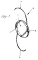
- Figure 1 is a perspective view of a soft intraocular lens which can be prepared from a deformable optic made in accordance with the teachings of the method of this invention.
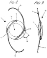
- Figure 2 is a front elevational view of the soft intraocular lens of Figure 1.
- Figure 3 is a right side elevational view of the soft intraocular lens of Figure 2.
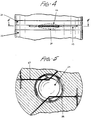
- Figure 4 is a partial side elevational view of a mold which can be used to prepare a deformable optic made in accordance with the method of this invention.
- Figure 5 is a cross-sectional view of the mold as taken along 5-5 of Figure 4.
- Figure 6 is a fragmentary perspective view showing a portion of a deformable optic made in accordance with the method of this invention.
- Figure 7 is a cross-sectional view of the wire-like insert member used to make the deformable optic in accordance with the method of this invention.
- Figure 8 is a cross-sectional view of the proximal end portion of a filamentary fixation member which can be used to prepare a soft intraocular lens from the deformable optic.
- FIGS 1-3 show a preferred soft intraocular lens ("IOL") made from a deformable optic in accordance with the method of this invention.
- IOL 10 has a deformable optic 11 with an optic zone 12 and a peripheral zone 13. The peripheral zone is not in the field of vision of the patient after the lens is implanted in the eye.
- Deformable optic 11 can be made of any transparent, biocompatible material suitable for ophthalmic applications, provided the material can be "cured” to form the optic.
- curable is used in the broad sense to describe any material which can be processed in a practical manner to form the optic. Such materials include polymerizable monomers, regardless whether the monomer polymerizes to form a thermoplastic or thermoset. Ideally, the material is pourable so it can be poured into the mold to substantially fill the mold cavity easily and conveniently.
- the optic is derived from a polymerizable monomer, especially from the polymerization of a silicone monomer.
- the proximal end portion of each filamentary fixation member preferably has a bend of approximately 45°. This bend is desired to increase resistance to movement, and therefore to increase the force necessary to remove the filamentary fixation member from the optic and to prevent the filamentary fixation member from rotating. To achieve this purpose, the bend angle only needs to be at least approximately 30°. The angle of the bend can be decreased or increased, and the optimum angle will depend on the composition of the optic and filamentary fixation members, as well as on the degree of resistance desired for any given application.
- Figure 3 illustrates the preferred biconvex structure of the circular optic, however any optical configuration suitable for an IOL is within the scope of this invention.
- the shape of the optic can be not only circular but also oval, and the optic geometry can be in the form of a plano convex configuration.
- the filamentary fixation members can be made of any biocompatible material which can be processed to fabricate the desired filamentary structure. Such materials include polypropylene, polymethylmethacrylate, certain polyamides and fluorocarbons such as polyvinylidene fluoride and other high temperature thermoplastics. The preferred material is polypropylene.
- the configuration of the filamentary fixation members can be in any form conventionally used for IOL design, but the preferred configuration is known as the modified J configuration shown in Figures 1-3.
- the process of molding the"curable material which forms the deformable optic about the wire-like insert member can be carried out using conventional cast molding techniques.
- the process described in U.S. Patent 4,978,354 for molding a soft IOL can be used to prepare the deformable optic made according to the invention, except the wire-like insert members are embedded in the mold cavity in place of the filamentary fixation members.
- Figures 4 and 5 illustrate a conventional mold at 20 which can be used to prepare the deformable optic of this invention.
- the mold has a top mold half 21 with a desired mold cavity 22, and an opposing and complementary bottom mold half 23 with a bottom mold cavity 24.
- Channel 25 is for positioning a first wire-like insert member.
- wire-like insert members 26 and 27 are positioned within their respective channels in the mold. The channels correspond to the desired configuration and location of the openings in the molded optic for securely receiving proximal end portions 15 and 17 of filamentary fixation members 14 and 16, respectively.
- the mold cavity is then filled with the selected curable material containing any other desired ingredients.
- the top mold half is mated and fastened to the bottom mold half.
- the curable composition is subsequently cured using conventional techniques of heat, pressure and time.
- the wire-like insert member used in the method of this invention should have a softening temperature higher than that of the curable material,, so that when such material is cured, it does not deformthe wire-like insert member.
- the wire-like insert member preferably is composed of a material that exhibits low toxicity, is stable at processing temperatures, and is suitable for medical device applications. It should not be reactive with the curable material chosen to form the molded optic.
- the wire-like insert member must be formable to any desired configuration.
- the preferred configuration is such that a portion of the wire-like insert member has a configuration substantially identical to that of the proximal end portion of the filamentary fixation members depicted in Figure 2.
- the preferred wire-like insert members are stainless steel and polyaramide fibers.
- the most preferred wire-like insert member is a stainless steel wire.
- the wire-like insert member preferably has a uniform cross-sectional diameter along its entire length, and only a portion of the wire-like insert member is positioned within the mold cavity. In this manner, it is easy to remove the wire-like insert member after the optic is molded by pulling on that portion of the wire-like insert member which was not positioned in the mold cavity.
- the mold halves are separated, any excess material is deflashed, and the molded optic with the wire-like insert members embedded therein is removed from the mold.
- the wire-like insert member is removed from the molded optic, leaving behind the opening in the molded optic which conforms to the desired shape of the proximal end portion of the filamentary fixation members.
- the opening made from the removal of the wire-like insert member extends from a first peripheral edge position 31 to a second peripheral edge position 32 in a plane parallel to the plane of the optic.
- proximal end portion 15 of the filamentary fixation member can be securely inserted into the opening 30 for final fabrication of the soft IOL.
- the filamentary fixation member can be pushed into the opening through peripheral edge position 32, and as the filamentary fixation member is pushed through the opening, any air which is entrapped in the opening can escape at peripheral edge position 31.
- localized heat can be applied for a short time to optimize the ability of the proximal end portion of the filamentary fixation member to conform to the configuration of the opening, especially at the bend.
- the proximal end portion of the filamentary fixation member desirably has a cross-sectional diameter, D, greater than the cross-sectional diameter of the wire-like insert member, d (although the invention can be used effectively when the diameters are substantially equal). Therefore, the diameter of the proximal end portion will be greater than the opening in the molded optic when the wire-like insert member is removed.
- the increased diameter of the proximal end portion of the filamentary fixation member serves to further increase the pull force necessary to remove the filamentary fixation member from the optic.
- the proximal end portion of the filamentary fixation member prefferably has a larger diameter than that of the opening of the deformable optic because as the filamentary fixation member is pushed into the opening, the opening expands to fit the diameter of the proximal end portion of the filamentary fixation member.
Abstract
Description
- This invention relates to a method of molding a deformable optic for a soft intraocular lens. More specifically, it relates to a method of molding such an optic which has an opening therein for securely receiving a haptic, which is the filamentary strand supporting the optic of the intraocular lens in the eye.
- Flexible intraocular lenses which can be deformed to facilitate insertion through a small incision in the eye have steadily gained popularity in recent years. In contrast to conventional rigid intraocular lenses, for example, polymethylmethacrylate (PMMA) lenses, "soft" intraocular lenses offer advantages for ophthalmic surgeons with respect to the way in which the lens can be inserted in the eye. Since a soft intraocular lens can be folded or compressed to fit through a corneal incision having a diameter smaller than that'of the soft lens in an undeformed condition, the patient receiving the intraocular lens will experience less surgical trauma and a shortened recovery period.
- Although soft intraocular lenses have demonstrated numerous practical advantages for the ophthalmic surgeon, technological difficulties still remain for the preparation of these lenses. Scientists and engineers have continually worked on successfully attaching the haptic to the optic of the intraocular lens. The haptic supports the optic in the eye and therefore performs a necessary function for the successful operation of the lens. The traditional machining and staking processes for attaching the haptic to a rigid optic are inappropriate for soft optic attachment because of the flexible, deformable nature of the soft optic. Numerous attempts have been made to provide methods for securely fastening the haptic to a soft optic of an intraocular lens.
- U.S. Patent Nos. 4,880,426 and 4,894,062 disclose molding the material from which the deformable optic is derived about a portion of the haptic of the intraocular lens. That portion of the haptic which is embedded within the molded optic is configured in such a manner so as to securely attach the haptic to the optic. For example, the tip of the haptic embedded in the optic may be "balled" by applying heat to the tip to soften the haptic, or the haptic may be attached to an anchoring member which may be in the form of an arcuate filamentary strand or an elongated rod. U.S. Patent 4,786,445 discloses the use of laser energy to attach the haptic to a soft optic of an intraocular lens.
- Although the methods described above eliminate the need to use conventional means for attaching the haptic to the optic, these methods have their drawbacks. Foremost among the problems associated with these methods is that the portion of the haptic embedded in the optic is subjected to the curing temperature required to mold the material from which the soft optic is prepared. Unfortunately, the elevated temperature associated with the curing operation will cause the filamentary haptic strand to deform. This deformation may significantly affect the performance of the haptic for supporting the optic of the intraocular lens securely within the eye. It is most pronounced with haptics composed of the most commonly used materials, such as polypropylene and polymethylmethacrylate. These polymeric materials have softening temperatures which are below the temperatures required to cure the material from which the optic is made.
- WO-A-9004512 discloses a method of forming an intraocular lens including moulding a pair of core pins within the lens to produce a pair of haptic moulding holes. The holes are larger than the diameter of the haptic to enable the haptic to be positioned at different angles. The method of this document has the disadvantage of requiring the haptic to be glued within the holes to secure it in a chosen position.
- Therefore, in view of the deficiencies inherent in prior art methods for attaching a filamentary fixation member to a soft, deformable optic, a new method is needed for securely fastening a haptic to such an optic.
- The invention is a method of molding a deformable optic for a soft intraocular lens as defined in the claims. The optic has at least one opening therein for securely receiving a proximal end portion of a filamentary fixation member. The method comprises the sequential steps of positioning a wire-like insert member in a mold for the optic at a location corresponding to the desired location of the opening; filling the mold about the wire-like insert member with a curable material selected to form the deformable optic; curing the material so as to form the molded optic with the wire-like insert member embedded therein; and removing the wire-like insert member from the molded optic.
- The method of this invention can be used to mold a deformable optic having an opening therein for securely receiving a filamentary fixation member, or "haptic", of an intraocular lens. Once the optic is formed with the opening, the haptic can be readily inserted into the opening for secure attachment of the haptic to the optic.
- The opening formed in the optic has a cross-sectional diameter smaller or substantially equal to that of the haptic. It is unnecessary to use the conventional staking or machining methods associated with rigid lenses for haptic attachment. More significantly, it is unnecessary to subject the haptic to the elevated temperature necessary for curing the material from which the optic is made. Therefore, it eliminates the disadvantage of deforming the haptic when the haptic is attached to the molded optic.
- Figure 1 is a perspective view of a soft intraocular lens which can be prepared from a deformable optic made in accordance with the teachings of the method of this invention.
- Figure 2 is a front elevational view of the soft intraocular lens of Figure 1.
- Figure 3 is a right side elevational view of the soft intraocular lens of Figure 2.
- Figure 4 is a partial side elevational view of a mold which can be used to prepare a deformable optic made in accordance with the method of this invention.
- Figure 5 is a cross-sectional view of the mold as taken along 5-5 of Figure 4.
- Figure 6 is a fragmentary perspective view showing a portion of a deformable optic made in accordance with the method of this invention.
- Figure 7 is a cross-sectional view of the wire-like insert member used to make the deformable optic in accordance with the method of this invention.
- Figure 8 is a cross-sectional view of the proximal end portion of a filamentary fixation member which can be used to prepare a soft intraocular lens from the deformable optic.
- Figures 1-3 show a preferred soft intraocular lens ("IOL") made from a deformable optic in accordance with the method of this invention. IOL 10 has a deformable optic 11 with an
optic zone 12 and aperipheral zone 13. The peripheral zone is not in the field of vision of the patient after the lens is implanted in the eye. - Deformable optic 11 can be made of any transparent, biocompatible material suitable for ophthalmic applications, provided the material can be "cured" to form the optic. The term "curable" is used in the broad sense to describe any material which can be processed in a practical manner to form the optic. Such materials include polymerizable monomers, regardless whether the monomer polymerizes to form a thermoplastic or thermoset. Ideally, the material is pourable so it can be poured into the mold to substantially fill the mold cavity easily and conveniently. Preferably, the optic is derived from a polymerizable monomer, especially from the polymerization of a silicone monomer.
- Attached to the deformable optic of the IOL are
filamentary fixation members proximal end portions - Figure 3 illustrates the preferred biconvex structure of the circular optic, however any optical configuration suitable for an IOL is within the scope of this invention. For example, the shape of the optic can be not only circular but also oval, and the optic geometry can be in the form of a plano convex configuration.
- The filamentary fixation members can be made of any biocompatible material which can be processed to fabricate the desired filamentary structure. Such materials include polypropylene, polymethylmethacrylate, certain polyamides and fluorocarbons such as polyvinylidene fluoride and other high temperature thermoplastics. The preferred material is polypropylene. The configuration of the filamentary fixation members can be in any form conventionally used for IOL design, but the preferred configuration is known as the modified J configuration shown in Figures 1-3.
- The process of molding the"curable material which forms the deformable optic about the wire-like insert member can be carried out using conventional cast molding techniques. In fact, the process described in U.S. Patent 4,978,354 for molding a soft IOL can be used to prepare the deformable optic made according to the invention, except the wire-like insert members are embedded in the mold cavity in place of the filamentary fixation members.
- Figures 4 and 5 illustrate a conventional mold at 20 which can be used to prepare the deformable optic of this invention. The mold has a
top mold half 21 with a desired mold cavity 22, and an opposing and complementarybottom mold half 23 with abottom mold cavity 24.Channel 25 is for positioning a first wire-like insert member. As shown in more detail in Figure 5, wire-like insert members proximal end portions filamentary fixation members - Once the wire-like insert members are properly positioned in their respective channels in the bottom mold half, the mold cavity is then filled with the selected curable material containing any other desired ingredients. The top mold half is mated and fastened to the bottom mold half. The curable composition is subsequently cured using conventional techniques of heat, pressure and time.
- The wire-like insert member used in the method of this invention should have a softening temperature higher than that of the curable material,, so that when such material is cured, it does not deformthe wire-like insert member. The wire-like insert member preferably is composed of a material that exhibits low toxicity, is stable at processing temperatures, and is suitable for medical device applications. It should not be reactive with the curable material chosen to form the molded optic. Furthermore, the wire-like insert member must be formable to any desired configuration. The preferred configuration is such that a portion of the wire-like insert member has a configuration substantially identical to that of the proximal end portion of the filamentary fixation members depicted in Figure 2. The preferred wire-like insert members are stainless steel and polyaramide fibers. The most preferred wire-like insert member is a stainless steel wire.
- The wire-like insert member preferably has a uniform cross-sectional diameter along its entire length, and only a portion of the wire-like insert member is positioned within the mold cavity. In this manner, it is easy to remove the wire-like insert member after the optic is molded by pulling on that portion of the wire-like insert member which was not positioned in the mold cavity.
- After the optic material is cured, the mold halves are separated, any excess material is deflashed, and the molded optic with the wire-like insert members embedded therein is removed from the mold. As illustrated in Figure 6, the wire-like insert member is removed from the molded optic, leaving behind the opening in the molded optic which conforms to the desired shape of the proximal end portion of the filamentary fixation members. In the preferred embodiment, the opening made from the removal of the wire-like insert member extends from a first
peripheral edge position 31 to a secondperipheral edge position 32 in a plane parallel to the plane of the optic. - Once the wire-like insert member is removed,
proximal end portion 15 of the filamentary fixation member can be securely inserted into theopening 30 for final fabrication of the soft IOL. The filamentary fixation member can be pushed into the opening throughperipheral edge position 32, and as the filamentary fixation member is pushed through the opening, any air which is entrapped in the opening can escape atperipheral edge position 31. If desired, once the proximal end portion of the filamentary fixation member is fully positioned in the opening of the optic, localized heat can be applied for a short time to optimize the ability of the proximal end portion of the filamentary fixation member to conform to the configuration of the opening, especially at the bend. - As illustrated in Figures 7 and 8, the proximal end portion of the filamentary fixation member desirably has a cross-sectional diameter, D, greater than the cross-sectional diameter of the wire-like insert member, d (although the invention can be used effectively when the diameters are substantially equal). Therefore, the diameter of the proximal end portion will be greater than the opening in the molded optic when the wire-like insert member is removed. The increased diameter of the proximal end portion of the filamentary fixation member serves to further increase the pull force necessary to remove the filamentary fixation member from the optic. It is possible for the proximal end portion of the filamentary fixation member to have a larger diameter than that of the opening of the deformable optic because as the filamentary fixation member is pushed into the opening, the opening expands to fit the diameter of the proximal end portion of the filamentary fixation member.
- The invention has been described in its preferred embodiments. Numerous additional embodiments will become apparent to those skilled in this art, and such additional embodiments are well within the scope of the claimed invention.
Claims (12)
- A method of forming a deformable optic (11) with at least one filamentary fixation member (14) for a soft intraocular lens (10), wherein the optic (11) has at least one opening (30) therein for securely receiving a proximal end portion (15) of the filamentary fixation member (14), comprising the sequential steps of:a) positioning at least one wire-like insert member (26) in a mould (20) for the optic (11) at a location corresponding to the desired location of the opening (30), wherein the cross-sectional diameter of the wire-like insert member (26) is substantially equal to or smaller than that of the proximal end portion (15) of the filamentary fixation member (14);b) filling the mould (20) about the wire-like insert member (26) with a curable material selected to form the deformable optic (11);c) curing the material so as to form the moulded optic (11) with the wire-like insert member (26) embedded therein;d) removing the wire-like insert member (26) from the moulded optic (11) thus leaving a first opening (30); ande) inserting the proximal end portion (15) of the first filamentary fixation member (14) in the first opening (30).
- The method of claim 1, wherein the wire-like insert member (26) is a stainless steel wire.
- The method of claim 1 or claim 2, wherein the wire-like insert member (26) has a uniform cross-sectional diameter.
- The method of claims 1 to 3, wherein only a portion of the wire-like insert member (26) is embedded in the moulded optic (11).
- The method of claims 1 to 4, wherein the wire-like insert member (26) is embedded at or near the periphery of the moulded optic (11) outside the optic zone (12).
- The method of any one of claims 1 to 5, wherein the wire-like insert member (26) is embedded within a plane parallel to the plane of the optic (11).
- The method of any one of claims 1 to 6, wherein the portion of the wire-like insert member (26) embedded in the moulded optic (11) has a bend of at least about 30°, preferably at least about 45°.
- The method of any one of claim 1 to 7, wherein the wire-like insert member (26) embedded in the moulded optic (11) extends from a first peripheral edge position (31) to a second peripheral edge position (32).
- The method of claims 1 to 8, wherein the method further comprises the step of removing a second wire-like insert member (26) from the moulded optic such that the optic (11) has a second opening therein for securely receiving a proximal end portion (17) of a second filamentary fixation member (16), said second opening being spaced about 180° apart from the first opening and having substantially an identical configuration to that of the first opening.
- The method of claim 9, wherein the method further comprises the step of inserting the proximal end portion (17) of the second filamentary fixation member (16) in the second opening so as to prepare the soft intraocular lens (10).
- The method of any one of claims 1 to 10, wherein the curable material is a polymerizable monomer, preferably a silicone monomer.
- A soft intraocular lens (10) having a deformable optic (11) having a proximal end portion (15) of a filamentary fixation member (14) received in an opening in the optic (11) and held in place in the opening of the optic by an interference fit characterised in that the cross-sectional diameter of the opening in an undeformed state is substantially equal to or smaller than that of the proximal end portion (15) of the filamentary fixation member (14).
Applications Claiming Priority (2)
| Application Number | Priority Date | Filing Date | Title |
|---|---|---|---|
| US07/834,458 US5266241A (en) | 1992-02-12 | 1992-02-12 | Haptic attachment for soft intraocular lens |
| US834458 | 1992-02-12 |
Publications (2)
| Publication Number | Publication Date |
|---|---|
| EP0556040A1 EP0556040A1 (en) | 1993-08-18 |
| EP0556040B1 true EP0556040B1 (en) | 1997-10-15 |
Family
ID=25266992
Family Applications (1)
| Application Number | Title | Priority Date | Filing Date |
|---|---|---|---|
| EP93300985A Expired - Lifetime EP0556040B1 (en) | 1992-02-12 | 1993-02-11 | Haptic attachment for soft intraocular lens |
Country Status (8)
| Country | Link |
|---|---|
| US (1) | US5266241A (en) |
| EP (1) | EP0556040B1 (en) |
| KR (1) | KR930017558A (en) |
| AT (1) | ATE159165T1 (en) |
| AU (1) | AU665503B2 (en) |
| CA (1) | CA2089320C (en) |
| DE (1) | DE69314510T2 (en) |
| TW (1) | TW235272B (en) |
Cited By (1)
| Publication number | Priority date | Publication date | Assignee | Title |
|---|---|---|---|---|
| US6692525B2 (en) | 1992-02-28 | 2004-02-17 | Advanced Medical Optics, Inc. | Intraocular lens |
Families Citing this family (31)
| Publication number | Priority date | Publication date | Assignee | Title |
|---|---|---|---|---|
| US5185107A (en) * | 1988-10-26 | 1993-02-09 | Iovision, Inc. | Fabrication of an intraocular lens |
| US7284769B2 (en) * | 1995-06-07 | 2007-10-23 | Automotive Technologies International, Inc. | Method and apparatus for sensing a vehicle crash |
| US5476513A (en) * | 1992-02-28 | 1995-12-19 | Allergan, Inc. | Intraocular lens |
| US5282853A (en) * | 1992-09-29 | 1994-02-01 | Iolab Corporation | Intraocular lens with resilient haptics |
| JP3379717B2 (en) * | 1993-07-15 | 2003-02-24 | キヤノンスター株式会社 | Deformable intraocular lens |
| US5523029A (en) * | 1995-02-01 | 1996-06-04 | Alcon Laboratories, Inc. | Method of attaching a haptic to an optic of an intraocular lens |
| US5716403A (en) * | 1995-12-06 | 1998-02-10 | Alcon Laboratories, Inc. | Single piece foldable intraocular lens |
| WO1998005273A1 (en) * | 1996-08-06 | 1998-02-12 | Chiron Vision Corporation | Foldable intraocular lens |
| DE19805780A1 (en) * | 1998-02-12 | 1999-09-09 | Anschuetz | Intraocular lens |
| US6468306B1 (en) | 1998-05-29 | 2002-10-22 | Advanced Medical Optics, Inc | IOL for inhibiting cell growth and reducing glare |
| US6352542B1 (en) * | 2000-03-08 | 2002-03-05 | Michael E. Snyder | Intraocular lens with improved haptic and method of implanting same |
| US7179292B2 (en) * | 2002-03-15 | 2007-02-20 | Ophtec B.V. | Intraocular lens for implantation in an eye and instrument and methods for insertion of such a lens |
| US7628810B2 (en) | 2003-05-28 | 2009-12-08 | Acufocus, Inc. | Mask configured to maintain nutrient transport without producing visible diffraction patterns |
| US20050178733A1 (en) * | 2003-12-30 | 2005-08-18 | Conger Harry C. | Sub-critical oxidative processes |
| US9730787B2 (en) * | 2006-10-04 | 2017-08-15 | Hoya Corporation | Soft intraocular lens |
| EP2399548B1 (en) | 2009-02-20 | 2017-12-20 | Hoya Corporation | Soft intraocular lens and method of manufacturing same |
| AU2010282311B2 (en) | 2009-08-13 | 2015-08-13 | Acufocus, Inc. | Masked intraocular implants and lenses |
| US10004593B2 (en) | 2009-08-13 | 2018-06-26 | Acufocus, Inc. | Intraocular lens with elastic mask |
| EP2785296B1 (en) | 2011-12-02 | 2018-06-20 | AcuFocus, Inc. | Ocular mask having selective spectral transmission |
| US20140131905A1 (en) * | 2012-11-09 | 2014-05-15 | Acufocus, Inc. | Process for manufacturing an intraocular lens |
| US9427922B2 (en) | 2013-03-14 | 2016-08-30 | Acufocus, Inc. | Process for manufacturing an intraocular lens with an embedded mask |
| US11109957B2 (en) | 2014-09-22 | 2021-09-07 | Onpoint Vision, Inc. | Intraocular pseudophakic contact lens with mechanism for securing by anterior leaflet of capsular wall and related system and method |
| US10945832B2 (en) | 2014-09-22 | 2021-03-16 | Onpoint Vision, Inc. | Intraocular pseudophakic contact lens with mechanism for securing by anterior leaflet of capsular wall and related system and method |
| US10299910B2 (en) | 2014-09-22 | 2019-05-28 | Kevin J. Cady | Intraocular pseudophakic contact lens with mechanism for securing by anterior leaflet of capsular wall and related system and method |
| US10159562B2 (en) | 2014-09-22 | 2018-12-25 | Kevin J. Cady | Intraocular pseudophakic contact lenses and related systems and methods |
| US11938018B2 (en) | 2014-09-22 | 2024-03-26 | Onpoint Vision, Inc. | Intraocular pseudophakic contact lens (IOPCL) for treating age-related macular degeneration (AMD) or other eye disorders |
| US9943403B2 (en) | 2014-11-19 | 2018-04-17 | Acufocus, Inc. | Fracturable mask for treating presbyopia |
| EP3359987B1 (en) | 2015-10-05 | 2024-02-28 | AcuFocus, Inc. | Methods of molding intraocular lenses |
| EP3384342B1 (en) | 2015-11-24 | 2021-08-25 | AcuFocus, Inc. | Toric small aperture intraocular lens with extended depth of focus |
| KR200481379Y1 (en) | 2015-12-02 | 2016-09-22 | 정은화 | Sleeve for protection against the cold |
| WO2019217471A1 (en) | 2018-05-09 | 2019-11-14 | Acufocus, Inc. | Intraocular implant with removable optic |
Family Cites Families (8)
| Publication number | Priority date | Publication date | Assignee | Title |
|---|---|---|---|---|
| US4068933A (en) * | 1975-03-18 | 1978-01-17 | Maurice Seiderman | Fenestrated hydrogels for contact lens use and method for making same |
| US4015965A (en) * | 1975-12-22 | 1977-04-05 | American Optical Corporation | Method of making artificial intraocular lenses with holes |
| US4025965A (en) * | 1976-03-16 | 1977-05-31 | American Optical Corporation | Intraocular lenses |
| US4786445A (en) * | 1985-07-11 | 1988-11-22 | Allergan, Inc. | Method of attaching a fixation member to an intraocular lens |
| US4894062A (en) * | 1985-12-04 | 1990-01-16 | Allergan, Inc. | Staking anchor for soft IOL |
| US4880426A (en) * | 1985-12-09 | 1989-11-14 | Allergan, Inc. | Haptic to optic attachment for a soft IOL |
| US5104590A (en) * | 1988-10-26 | 1992-04-14 | Wright Medical, Inc. | Fabrication of an intraocular lens |
| US4936849A (en) * | 1988-03-15 | 1990-06-26 | Minnesota Mining And Manufacturing Company | Intraocular lens |
-
1992
- 1992-02-12 US US07/834,458 patent/US5266241A/en not_active Expired - Lifetime
-
1993
- 1993-02-11 DE DE69314510T patent/DE69314510T2/en not_active Expired - Fee Related
- 1993-02-11 CA CA002089320A patent/CA2089320C/en not_active Expired - Fee Related
- 1993-02-11 AT AT93300985T patent/ATE159165T1/en not_active IP Right Cessation
- 1993-02-11 AU AU33004/93A patent/AU665503B2/en not_active Ceased
- 1993-02-11 EP EP93300985A patent/EP0556040B1/en not_active Expired - Lifetime
- 1993-02-11 KR KR1019930001837A patent/KR930017558A/en not_active Application Discontinuation
- 1993-04-29 TW TW082103312A patent/TW235272B/zh active
Cited By (1)
| Publication number | Priority date | Publication date | Assignee | Title |
|---|---|---|---|---|
| US6692525B2 (en) | 1992-02-28 | 2004-02-17 | Advanced Medical Optics, Inc. | Intraocular lens |
Also Published As
| Publication number | Publication date |
|---|---|
| AU3300493A (en) | 1993-08-19 |
| US5266241A (en) | 1993-11-30 |
| TW235272B (en) | 1994-12-01 |
| CA2089320A1 (en) | 1993-08-13 |
| EP0556040A1 (en) | 1993-08-18 |
| CA2089320C (en) | 2002-04-02 |
| DE69314510T2 (en) | 1998-04-02 |
| AU665503B2 (en) | 1996-01-04 |
| KR930017558A (en) | 1993-09-20 |
| DE69314510D1 (en) | 1997-11-20 |
| ATE159165T1 (en) | 1997-11-15 |
Similar Documents
| Publication | Publication Date | Title |
|---|---|---|
| EP0556040B1 (en) | Haptic attachment for soft intraocular lens | |
| US5567365A (en) | Method of producing repositionable intraocular lenses | |
| US10206773B2 (en) | Accommodating intraocular lens and method of manufacture thereof | |
| EP0667754B1 (en) | Intraocular lens with improved cylindrical haptic | |
| US5141507A (en) | Soft intraocular lens | |
| US4615702A (en) | Intraocular lens and method of forming the lens | |
| US6592621B1 (en) | Flexible intra-ocular lens of variable focus | |
| US6645246B1 (en) | Intraocular lens with surrounded lens zone | |
| EP1212010B1 (en) | Intraocular lens with a translational zone | |
| US7632431B2 (en) | Composite intraocular lens and method of manufacture thereof | |
| US4702865A (en) | Method of forming an intraocular lens | |
| WO1999027978A1 (en) | Intraocular lenses and process for producing molded-in type intraocular lenses | |
| JPH09108246A (en) | Improved intraocular implant structure with polyimide tactile part, and its manufacturing method | |
| US6533814B1 (en) | Intraocular lens having a design for controlling its axial displacement after implantation | |
| WO2002019949A2 (en) | Intraocular lens with a posterior lens portion | |
| EP0910503B1 (en) | IOLs AND PRODUCTION METHODS FOR SAME | |
| EP3230053B1 (en) | Apparatus and method of manufacture of intraocular lenses | |
| JPH0767896A (en) | Intraocular implant | |
| US5207708A (en) | Artificial eye lens and method of implanting same |
Legal Events
| Date | Code | Title | Description |
|---|---|---|---|
| PUAI | Public reference made under article 153(3) epc to a published international application that has entered the european phase |
Free format text: ORIGINAL CODE: 0009012 |
|
| AK | Designated contracting states |
Kind code of ref document: A1 Designated state(s): AT BE CH DE ES FR GB IE IT LI LU NL PT SE |
|
| 17P | Request for examination filed |
Effective date: 19940121 |
|
| 17Q | First examination report despatched |
Effective date: 19950428 |
|
| GRAG | Despatch of communication of intention to grant |
Free format text: ORIGINAL CODE: EPIDOS AGRA |
|
| GRAH | Despatch of communication of intention to grant a patent |
Free format text: ORIGINAL CODE: EPIDOS IGRA |
|
| GRAH | Despatch of communication of intention to grant a patent |
Free format text: ORIGINAL CODE: EPIDOS IGRA |
|
| GRAA | (expected) grant |
Free format text: ORIGINAL CODE: 0009210 |
|
| AK | Designated contracting states |
Kind code of ref document: B1 Designated state(s): AT BE CH DE ES FR GB IE IT LI LU NL PT SE |
|
| PG25 | Lapsed in a contracting state [announced via postgrant information from national office to epo] |
Ref country code: ES Free format text: THE PATENT HAS BEEN ANNULLED BY A DECISION OF A NATIONAL AUTHORITY Effective date: 19971015 Ref country code: BE Free format text: LAPSE BECAUSE OF FAILURE TO SUBMIT A TRANSLATION OF THE DESCRIPTION OR TO PAY THE FEE WITHIN THE PRESCRIBED TIME-LIMIT Effective date: 19971015 Ref country code: AT Free format text: LAPSE BECAUSE OF FAILURE TO SUBMIT A TRANSLATION OF THE DESCRIPTION OR TO PAY THE FEE WITHIN THE PRESCRIBED TIME-LIMIT Effective date: 19971015 |
|
| REF | Corresponds to: |
Ref document number: 159165 Country of ref document: AT Date of ref document: 19971115 Kind code of ref document: T |
|
| REG | Reference to a national code |
Ref country code: CH Ref legal event code: EP |
|
| REF | Corresponds to: |
Ref document number: 69314510 Country of ref document: DE Date of ref document: 19971120 |
|
| ET | Fr: translation filed | ||
| ITF | It: translation for a ep patent filed |
Owner name: MODIANO & ASSOCIATI S.R.L. |
|
| PG25 | Lapsed in a contracting state [announced via postgrant information from national office to epo] |
Ref country code: PT Free format text: LAPSE BECAUSE OF FAILURE TO SUBMIT A TRANSLATION OF THE DESCRIPTION OR TO PAY THE FEE WITHIN THE PRESCRIBED TIME-LIMIT Effective date: 19980115 |
|
| PG25 | Lapsed in a contracting state [announced via postgrant information from national office to epo] |
Ref country code: LU Free format text: LAPSE BECAUSE OF NON-PAYMENT OF DUE FEES Effective date: 19980211 Ref country code: IE Free format text: LAPSE BECAUSE OF NON-PAYMENT OF DUE FEES Effective date: 19980211 |
|
| REG | Reference to a national code |
Ref country code: CH Ref legal event code: NV Representative=s name: PATENTANWAELTE SCHAAD, BALASS, MENZL & PARTNER AG |
|
| PLBE | No opposition filed within time limit |
Free format text: ORIGINAL CODE: 0009261 |
|
| STAA | Information on the status of an ep patent application or granted ep patent |
Free format text: STATUS: NO OPPOSITION FILED WITHIN TIME LIMIT |
|
| 26N | No opposition filed | ||
| REG | Reference to a national code |
Ref country code: GB Ref legal event code: IF02 |
|
| PGFP | Annual fee paid to national office [announced via postgrant information from national office to epo] |
Ref country code: CH Payment date: 20040319 Year of fee payment: 12 |
|
| PGFP | Annual fee paid to national office [announced via postgrant information from national office to epo] |
Ref country code: SE Payment date: 20050203 Year of fee payment: 13 |
|
| PG25 | Lapsed in a contracting state [announced via postgrant information from national office to epo] |
Ref country code: LI Free format text: LAPSE BECAUSE OF NON-PAYMENT OF DUE FEES Effective date: 20050228 Ref country code: CH Free format text: LAPSE BECAUSE OF NON-PAYMENT OF DUE FEES Effective date: 20050228 |
|
| REG | Reference to a national code |
Ref country code: FR Ref legal event code: TP |
|
| REG | Reference to a national code |
Ref country code: CH Ref legal event code: PL |
|
| REG | Reference to a national code |
Ref country code: GB Ref legal event code: 732E |
|
| PG25 | Lapsed in a contracting state [announced via postgrant information from national office to epo] |
Ref country code: SE Free format text: LAPSE BECAUSE OF NON-PAYMENT OF DUE FEES Effective date: 20060212 |
|
| EUG | Se: european patent has lapsed | ||
| PGFP | Annual fee paid to national office [announced via postgrant information from national office to epo] |
Ref country code: NL Payment date: 20090210 Year of fee payment: 17 Ref country code: DE Payment date: 20090227 Year of fee payment: 17 |
|
| PGFP | Annual fee paid to national office [announced via postgrant information from national office to epo] |
Ref country code: GB Payment date: 20090106 Year of fee payment: 17 |
|
| PGFP | Annual fee paid to national office [announced via postgrant information from national office to epo] |
Ref country code: IT Payment date: 20090213 Year of fee payment: 17 |
|
| PGFP | Annual fee paid to national office [announced via postgrant information from national office to epo] |
Ref country code: FR Payment date: 20090206 Year of fee payment: 17 |
|
| REG | Reference to a national code |
Ref country code: NL Ref legal event code: V1 Effective date: 20100901 |
|
| GBPC | Gb: european patent ceased through non-payment of renewal fee |
Effective date: 20100211 |
|
| REG | Reference to a national code |
Ref country code: FR Ref legal event code: ST Effective date: 20101029 |
|
| PG25 | Lapsed in a contracting state [announced via postgrant information from national office to epo] |
Ref country code: NL Free format text: LAPSE BECAUSE OF NON-PAYMENT OF DUE FEES Effective date: 20100901 Ref country code: FR Free format text: LAPSE BECAUSE OF NON-PAYMENT OF DUE FEES Effective date: 20100301 |
|
| PG25 | Lapsed in a contracting state [announced via postgrant information from national office to epo] |
Ref country code: DE Free format text: LAPSE BECAUSE OF NON-PAYMENT OF DUE FEES Effective date: 20100901 |
|
| PG25 | Lapsed in a contracting state [announced via postgrant information from national office to epo] |
Ref country code: IT Free format text: LAPSE BECAUSE OF NON-PAYMENT OF DUE FEES Effective date: 20100211 Ref country code: GB Free format text: LAPSE BECAUSE OF NON-PAYMENT OF DUE FEES Effective date: 20100211 |