EP0554632B1 - Releasable split bearing - Google Patents
Releasable split bearing Download PDFInfo
- Publication number
- EP0554632B1 EP0554632B1 EP92402684A EP92402684A EP0554632B1 EP 0554632 B1 EP0554632 B1 EP 0554632B1 EP 92402684 A EP92402684 A EP 92402684A EP 92402684 A EP92402684 A EP 92402684A EP 0554632 B1 EP0554632 B1 EP 0554632B1
- Authority
- EP
- European Patent Office
- Prior art keywords
- semi
- bearing
- cylindrical
- opening
- cylindrical shell
- Prior art date
- Legal status (The legal status is an assumption and is not a legal conclusion. Google has not performed a legal analysis and makes no representation as to the accuracy of the status listed.)
- Expired - Lifetime
Links
- 239000000463 material Substances 0.000 claims abstract description 22
- 230000013011 mating Effects 0.000 claims description 5
- 238000001035 drying Methods 0.000 claims description 4
- 239000011120 plywood Substances 0.000 claims description 3
- 230000002093 peripheral effect Effects 0.000 abstract description 5
- 230000000295 complement effect Effects 0.000 abstract description 4
- 230000037431 insertion Effects 0.000 description 2
- 238000003780 insertion Methods 0.000 description 2
- 238000009434 installation Methods 0.000 description 2
- 239000010425 asbestos Substances 0.000 description 1
- 230000004323 axial length Effects 0.000 description 1
- 238000005452 bending Methods 0.000 description 1
- 230000000694 effects Effects 0.000 description 1
- 230000001788 irregular Effects 0.000 description 1
- 238000004519 manufacturing process Methods 0.000 description 1
- 239000011505 plaster Substances 0.000 description 1
- 230000001681 protective effect Effects 0.000 description 1
- 239000012858 resilient material Substances 0.000 description 1
- 229910052895 riebeckite Inorganic materials 0.000 description 1
Images

Classifications
-
- F—MECHANICAL ENGINEERING; LIGHTING; HEATING; WEAPONS; BLASTING
- F16—ENGINEERING ELEMENTS AND UNITS; GENERAL MEASURES FOR PRODUCING AND MAINTAINING EFFECTIVE FUNCTIONING OF MACHINES OR INSTALLATIONS; THERMAL INSULATION IN GENERAL
- F16C—SHAFTS; FLEXIBLE SHAFTS; ELEMENTS OR CRANKSHAFT MECHANISMS; ROTARY BODIES OTHER THAN GEARING ELEMENTS; BEARINGS
- F16C33/00—Parts of bearings; Special methods for making bearings or parts thereof
- F16C33/02—Parts of sliding-contact bearings
- F16C33/04—Brasses; Bushes; Linings
- F16C33/06—Sliding surface mainly made of metal
- F16C33/08—Attachment of brasses, bushes or linings to the bearing housing
-
- F—MECHANICAL ENGINEERING; LIGHTING; HEATING; WEAPONS; BLASTING
- F16—ENGINEERING ELEMENTS AND UNITS; GENERAL MEASURES FOR PRODUCING AND MAINTAINING EFFECTIVE FUNCTIONING OF MACHINES OR INSTALLATIONS; THERMAL INSULATION IN GENERAL
- F16C—SHAFTS; FLEXIBLE SHAFTS; ELEMENTS OR CRANKSHAFT MECHANISMS; ROTARY BODIES OTHER THAN GEARING ELEMENTS; BEARINGS
- F16C35/00—Rigid support of bearing units; Housings, e.g. caps, covers
- F16C35/02—Rigid support of bearing units; Housings, e.g. caps, covers in the case of sliding-contact bearings
Definitions
- the present invention is directed to an improved hanger bearing assembly, more specifically one which can be firmly held in place and readily dismounted.
- a bearing assembly according to the preamble of claim 1 is known from US-A-3 022 126, wherein two semi-cylindrical halves of bearing material are provided in a cylindrical shell having flanges to attach it within an opening of a self-aligning bearing hanger unit.
- This known assembly is e.g. used in a dryer for plaster board.
- the assembly of the present invention is particularly useful in connection with certain forms of drying ovens, although it is also useful in many other areas.
- drying ovens are usually of the tunnel type and the articles to be dried (often plywood sheets) are passed therethrough on rollers.
- Each roller requires a minimum of two bearings and, due to the high temperatures employed, these bearings must be able to withstand such temperatures for substantial periods of time without failing. Since these ovens are quite long (some exceed 91 meter (300 feet)), there are a large number of transverse rollers and, consequently, at least double that number of bearings supporting them.
- the present invention is a bearing assembly comprising a shroud having a opening therethrough as defined in claim 1 and the use of such an assembly as defined in claim 4.
- the bearing itself is a cylindrical shell having the bearing material therein; the actual bearing surface being at its radially most inward level.
- the shell In its cylindrical form, the shell is appropriately sized so that it fits into the opening in the shroud.
- the shell is divided into two parts at points diametrically opposite each other.
- a hinge is located at one point and a latch at the other.
- the latch advantageously comprises a slot in one half of the shell adjacent the unhinged split point and a tongue on the other half of the shell adjacent the same point. The halves are moved with the aid of the hinge to the closed position in which the slot and tongue are abutting each other. The tongue passes through the slot and, since it is of bendable material, can be bent back so that it can no longer slip out. This securely holds the shell and bearing material in the closed cylindrical position.
- the shell is provided with at least one flange on its periphery extending radially outwardly therefrom.
- a complementary flange extends radially inwardly from the periphery of the opening.
- One of these two parts carries a male flange and the other a female flange. The latter is adapted to receive the former upon insertion of the shell into the opening and rotation thereof.
- the flanges extend only partly around the perimeter of the opening and the periphery of the shell so that there are portions of the periphery and the perimeter which carry no flange whatsoever.
- the unflanged portion of the opening is at least as long as the flange on the cylindrical shell and the unflanged peripheral space on the cylindrical shell is at least equal in length to the flange on the perimeter of the opening.
- a lock for axially retaining the shell within the opening and properly mounted on the shroud advantageously comprises a substantially cylindrical rim having a gap therein and at least two axially directed projections extending only partly around the circumference of the rim.
- the unflanged portion of the opening in the shroud is at least equal in length to the projections, so that they can extend therethrough.
- the lock is of resilient material and the projections, when the lock is in its relaxed state, are somewhat farther apart than the diameter of the opening. The rim may then be compressed so that the distance between the projections becomes smaller than the diameter of the opening, thus permitting insertion thereof. When the projections extend through the opening, the lock can be released so that it springs apart and bears against the perimeter of the opening in the shroud. This securely holds the bearing axially place.
- a preferred form of this embodiment carries at least one protuberance on each of the projections. These are located so that, when the projections are inserted into the opening, the protuberances are on the side of the shroud away from the rim. These protuberances act together with the perimeter of the opening in order to assist in preventing the bearing from accidentally or unintentionally being axially removed from the shroud.
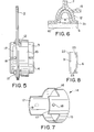
- Bearing assembly 1 comprises shroud 2 and bearing 19. Holes 13 are provided on shroud 2 for mounting the bearing at any desired location.
- Bearing 19 comprises semi-cylindrical shell 3 and complementary semi-cylindrical shell 4.
- Bearing material 9 is on the inner surfaces of shells 3 and 4 and is provided with bearing surfaces 10.
- bearing material 9 is housed in bearing holder 24.
- Shells 3 and 4 and bearing material 9 are split and connected by hinge 5, thus permitting shells 3 and 4 to move toward and away from each other.
- Diametrically opposite from hinge 5 is latch 20 composed of slot 7 and tongue 6. The latter is inserted into slot 7 and bent upwardly as shown in Figure 3, thereby securely and releasably latching shells 3 and 4 together in their closed, cylindrical position and forming hole 21 for receipt of shaft 11. This position is best shown in Figure 4.
- Shroud 2 is provided with an opening therethrough into which bearing 19 fits.
- Shroud 2 also carries female flanges 12 which project partially into the opening and shells 3 and 4 are provided with male flanges 8. Both female flanges 12 and male flanges 8 extend only partially around the perimeter of the opening and the circumferences of shells 3 and 4, respectively.
- lock 14 comprises rim 15 and projections 17.
- Gap 16 is provided at one point in rim 15 to permit lock 14, which is shown in its relaxed state in Figure 7, to be compressed.
- Projections 17 extend axially from rim 15 and are suitably sized so that they can pass through the unflanged portions of the perimeter of the opening shroud 2. Projections 17 also carry protuberances 18 which assist in holding the assembly together. These are best shown in Figure 5.
- mating faces 22 of bearing material 9 are substantially planar. Recessed portions 25 are provided to enable hinge 5 to close without fracturing bearing material 9. Planar mating faces 22, as compared to previously known irregular mating surfaces, permit easier installation of bearing material 9 as well as replacement of one semi-cylindrical half of bearing material 9 while retaining the other half. Tabs 23 secure bearing material 9 on holder 24. It is also advantageous if the length of semi-cylindrical bearing material 9 is slightly less than the axial length of half shell 3 or 4. This, coupled with tabs 23, makes the manufacture and installation of bearing material 9 much easier as the axial dimension is no longer critical and tabs 23 secure material 9 in place even if the axial dimensions are different.
- bearing 19 in its open position as shown in Figure 2, is placed adjacent shaft 11. Shells 3 and 4 are then caused to rotate about hinge 5 and are pressed closed as shown in Figure 4. Tongue 6 passes through slot 7 and is bent upwardly (see Figure 3) to lock bearing 19 in its closed position. Bearing 19 is turned so that male flanges 8 are located at the circumferential spaces between female flanges 12 on shroud 2.
- Bearing 19 is then moved axially into the opening until male flanges 8 are aligned with female flanges 12. Bearing 19 is then rotated about its axis so that male flanges 8 enter female flanges 12 and are fully contained therein. This is shown in Figure 1 and in section in Figure 6.
Landscapes
- Engineering & Computer Science (AREA)
- General Engineering & Computer Science (AREA)
- Mechanical Engineering (AREA)
- Sliding-Contact Bearings (AREA)
- Pivots And Pivotal Connections (AREA)
- Closures For Containers (AREA)
- Holders For Apparel And Elements Relating To Apparel (AREA)
- Storage Of Web-Like Or Filamentary Materials (AREA)
- Turbine Rotor Nozzle Sealing (AREA)
Abstract
Description
- The present invention is directed to an improved hanger bearing assembly, more specifically one which can be firmly held in place and readily dismounted.
- A bearing assembly according to the preamble of claim 1 is known from US-A-3 022 126, wherein two semi-cylindrical halves of bearing material are provided in a cylindrical shell having flanges to attach it within an opening of a self-aligning bearing hanger unit. This known assembly is e.g. used in a dryer for plaster board.
- The assembly of the present invention is particularly useful in connection with certain forms of drying ovens, although it is also useful in many other areas. Such drying ovens are usually of the tunnel type and the articles to be dried (often plywood sheets) are passed therethrough on rollers. Each roller requires a minimum of two bearings and, due to the high temperatures employed, these bearings must be able to withstand such temperatures for substantial periods of time without failing. Since these ovens are quite long (some exceed 91 meter (300 feet)), there are a large number of transverse rollers and, consequently, at least double that number of bearings supporting them.
- Should any substantial number of bearings fail, the plywood sheets could no longer be moved through the oven and the entire operation comes to a complete halt. Obviously, this is extremely serious and the economic losses are substantial.
- When this happens, it is imperative that the necessary bearing replacement take place as quickly as possible. Usually, substantially all of the bearings are replaced at the same time, in order to prevent a subsequent failure shortly after the bearings have been changed and to thereby minimize down time.
- Due to the high temperatures referred to above, it is necessary to allow the oven to cool down to a point at which workmen can handle the bearings. In order to minimize this time, the crew used to effect the change wears asbestos gloves and other similar protective clothing. This enables them to get started on the job while the equipment is still fairly hot.
- Therefore, it is the object of the present invention to provide an assembly wherein the bearing can be quickly and firmly connected to the shroud which, in turn, is attached to the frame of the device. It is also the object of the present invention to provide such an assembly wherein the bearing can be easily and quickly dismounted.
- The present invention is a bearing assembly comprising a shroud having a opening therethrough as defined in claim 1 and the use of such an assembly as defined in
claim 4. The bearing itself is a cylindrical shell having the bearing material therein; the actual bearing surface being at its radially most inward level. - In its cylindrical form, the shell is appropriately sized so that it fits into the opening in the shroud.
- In accordance with the invention, the shell is divided into two parts at points diametrically opposite each other. A hinge is located at one point and a latch at the other. In a preferred form of the invention, the latch advantageously comprises a slot in one half of the shell adjacent the unhinged split point and a tongue on the other half of the shell adjacent the same point. The halves are moved with the aid of the hinge to the closed position in which the slot and tongue are abutting each other. The tongue passes through the slot and, since it is of bendable material, can be bent back so that it can no longer slip out. This securely holds the shell and bearing material in the closed cylindrical position.
- In a preferred form of the invention, the shell is provided with at least one flange on its periphery extending radially outwardly therefrom. A complementary flange extends radially inwardly from the periphery of the opening. One of these two parts carries a male flange and the other a female flange. The latter is adapted to receive the former upon insertion of the shell into the opening and rotation thereof.
- The flanges extend only partly around the perimeter of the opening and the periphery of the shell so that there are portions of the periphery and the perimeter which carry no flange whatsoever. The unflanged portion of the opening is at least as long as the flange on the cylindrical shell and the unflanged peripheral space on the cylindrical shell is at least equal in length to the flange on the perimeter of the opening. As a result, there is sufficient room to allow the flanges to enter between one another and be circumferentially aligned for rotation of the male flange into the complementary female flange.
- In another preferred form of the invention, there are two flanges provided on each of the perimeter of the opening and periphery of the shell, thereby forming two peripheral gaps on the shell and two circumferential spaces on the periphery of the opening.
- For additional security, there can be added to the foregoing device a lock for axially retaining the shell within the opening and properly mounted on the shroud. The lock advantageously comprises a substantially cylindrical rim having a gap therein and at least two axially directed projections extending only partly around the circumference of the rim. The unflanged portion of the opening in the shroud is at least equal in length to the projections, so that they can extend therethrough.
- The lock is of resilient material and the projections, when the lock is in its relaxed state, are somewhat farther apart than the diameter of the opening. The rim may then be compressed so that the distance between the projections becomes smaller than the diameter of the opening, thus permitting insertion thereof. When the projections extend through the opening, the lock can be released so that it springs apart and bears against the perimeter of the opening in the shroud. This securely holds the bearing axially place.
- A preferred form of this embodiment carries at least one protuberance on each of the projections. These are located so that, when the projections are inserted into the opening, the protuberances are on the side of the shroud away from the rim. These protuberances act together with the perimeter of the opening in order to assist in preventing the bearing from accidentally or unintentionally being axially removed from the shroud.
- In the accompanying drawings, constituting a part hereof, and in which like reference characters indicate like parts,
- Figure 1
- is an axial view of the bearing assembly;
- Figure 2
- is an axial view of the bearing in its open position showing a shaft located therein;
- Figure 3
- is an edge view showing the two halves of the split bearing and the latch holding them together;
- Figure 4
- is a view similar to that of Figure 2 without the shaft and with the bearing in its closed position;
- Figure 5
- is an edge view taken from the right side of Figure 1;
- Figure 6
- is a cross section along line 6-6 of Figure 1;
- Figure 7
- is a perspective view of the lock; and
- Figure 8
- is an end view of an open face of the bearing.
- Bearing assembly 1 comprises
shroud 2 and bearing 19.Holes 13 are provided onshroud 2 for mounting the bearing at any desired location.Bearing 19 comprisessemi-cylindrical shell 3 and complementarysemi-cylindrical shell 4.Bearing material 9 is on the inner surfaces ofshells material 9 is housed in bearing holder 24.Shells bearing material 9 are split and connected byhinge 5, thus permittingshells hinge 5 islatch 20 composed ofslot 7 andtongue 6. The latter is inserted intoslot 7 and bent upwardly as shown in Figure 3, thereby securely and releasably latchingshells hole 21 for receipt of shaft 11. This position is best shown in Figure 4. -
Shroud 2 is provided with an opening therethrough into which bearing 19 fits.Shroud 2 also carriesfemale flanges 12 which project partially into the opening andshells male flanges 8. Bothfemale flanges 12 andmale flanges 8 extend only partially around the perimeter of the opening and the circumferences ofshells - As shown in Figure 7, lock 14 comprises
rim 15 andprojections 17.Gap 16 is provided at one point inrim 15 to permitlock 14, which is shown in its relaxed state in Figure 7, to be compressed.Projections 17 extend axially fromrim 15 and are suitably sized so that they can pass through the unflanged portions of the perimeter of theopening shroud 2.Projections 17 also carryprotuberances 18 which assist in holding the assembly together. These are best shown in Figure 5. - In accordance with the invention, mating faces 22 of bearing
material 9 are substantially planar. Recessedportions 25 are provided to enablehinge 5 to close without fracturingbearing material 9. Planar mating faces 22, as compared to previously known irregular mating surfaces, permit easier installation of bearingmaterial 9 as well as replacement of one semi-cylindrical half of bearingmaterial 9 while retaining the other half.Tabs 23secure bearing material 9 on holder 24. It is also advantageous if the length ofsemi-cylindrical bearing material 9 is slightly less than the axial length ofhalf shell tabs 23, makes the manufacture and installation of bearingmaterial 9 much easier as the axial dimension is no longer critical andtabs 23secure material 9 in place even if the axial dimensions are different. - To install the bearing of the present invention, bearing 19, in its open position as shown in Figure 2, is placed adjacent shaft 11.
Shells hinge 5 and are pressed closed as shown in Figure 4.Tongue 6 passes throughslot 7 and is bent upwardly (see Figure 3) to lockbearing 19 in its closed position.Bearing 19 is turned so thatmale flanges 8 are located at the circumferential spaces betweenfemale flanges 12 onshroud 2. -
Bearing 19 is then moved axially into the opening untilmale flanges 8 are aligned withfemale flanges 12.Bearing 19 is then rotated about its axis so thatmale flanges 8 enterfemale flanges 12 and are fully contained therein. This is shown in Figure 1 and in section in Figure 6. - Thereafter,
projections 17 onrim 15 oflock 14 are also placed circumferentially betweenfemale flanges 12 andlock 14 is axially inserted into the opening inshroud 2 untilprojections 17 assume the position shown in Figure 5.Protuberances 18 are located on the side ofshroud 2 away fromrim 15.Lock 14 is then released and, due to its resilience, springs apart and bears against the perimeter of the opening inshroud 2. This acts as a further lock and retains the bearing axially in place. - To remove the bearing, the foregoing steps are simply reversed.
Rim 15 oflock 14 is compressed (gap 16 permits this) and is withdrawn axially fromshroud 2. Thereafter, bearing 19 is rotated so thatmale flanges 8 are circumferentially betweenfemale flanges 12. This permits bearing 19 to be withdrawn axially fromshroud 2. Thereafter, if it is desired to replacebearing material 9, bearing 19 is opened by bendingtongue 6 downward as shown in Figure 3 and withdrawingtongue 6 fromslot 7. - While only a limited number of specific embodiments of the present invention have been expressed disclosed, it is, nonetheless, to be broadly construed, and not to be limited except by the scope of the claims appended hereto.
Claims (4)
- A bearing assembly (1) comprising a shroud (2) having an opening therethrough, said opening having a diameter and a perimeter, a substantially cylindrical shell (3, 4) having a periphery, an axis extending through said cylindrical shell (3, 4), two mating semi-cylindrical halves of bearing material (9) on said cylindrical shell extending radially inwardly thereof and forming a bearing surface, said cylindrical shell fitting within said opening, characterised in that said cylindrical shell (3,4) comprises a pair of substantially semi-cylindrical shells (3, 4) having a hinge (5) for motion in a direction perpendicular to said axis between a closed position wherein said semi-cylindrical shells form a cylinder and an open position wherein parts of said semi-cylindrical shells approximately diametrically opposite said hinge are spaced apart and a latch (20) releasably securing said shells in said closed position, said semi-cylindrical shells fitting within said opening when in said closed position, each said semi-cylindrical shell has one of said halves of semi-cylindrical bearing material thereon, and the mating faces of said halves of bearing material are substantially planar.
- The bearing assembly of Claim 1 wherein said halves of bearing material are secured in said semi-cylindrical shells by at least one tab (23) bearing against said halves of bearing material.
- The bearing assembly of Claim 1 wherein said latch comprises a slot (7) in one of said semi-cylindrical shells (4) adjacent said parts, a tongue (6) on another of said semi-cylindrical shells (3) adjacent said parts, said tongue (6) adapted to enter said slot (7) when said semi-cylindrical shells (3, 4) are in said closed position.
- Use of the bearing assembly according to Claim 1 in connection of drying ovens of the tunnel type, namely for drying plywood sheets.
Applications Claiming Priority (2)
| Application Number | Priority Date | Filing Date | Title |
|---|---|---|---|
| US831696 | 1992-02-05 | ||
| US07/831,696 US5169244A (en) | 1992-02-05 | 1992-02-05 | Releasable split bearing |
Publications (2)
| Publication Number | Publication Date |
|---|---|
| EP0554632A1 EP0554632A1 (en) | 1993-08-11 |
| EP0554632B1 true EP0554632B1 (en) | 1996-04-24 |
Family
ID=25259648
Family Applications (1)
| Application Number | Title | Priority Date | Filing Date |
|---|---|---|---|
| EP92402684A Expired - Lifetime EP0554632B1 (en) | 1992-02-05 | 1992-10-02 | Releasable split bearing |
Country Status (5)
| Country | Link |
|---|---|
| US (1) | US5169244A (en) |
| EP (1) | EP0554632B1 (en) |
| AT (1) | ATE137313T1 (en) |
| CA (1) | CA2075261C (en) |
| DE (2) | DE554632T1 (en) |
Families Citing this family (16)
| Publication number | Priority date | Publication date | Assignee | Title |
|---|---|---|---|---|
| DE4309425C1 (en) * | 1993-03-24 | 1994-06-01 | Lemfoerder Metallwaren Ag | Rubber-metal support for vehicle leaf-spring suspension - has two half shells joined by flexible end bars |
| EP0779190A1 (en) * | 1995-12-12 | 1997-06-18 | Valeo Systemes D'essuyage | Sheet metal support bearing for a windscreen wiper shaft |
| US5709482A (en) * | 1997-01-27 | 1998-01-20 | Lutz; David C. | Integrated hanger bearing |
| US6932512B2 (en) * | 2002-02-27 | 2005-08-23 | Deere & Company | Agricultural rockshaft bearing block structure and wear inserts therefor |
| US6513801B1 (en) * | 2002-07-24 | 2003-02-04 | The Pullman Company | Hinged/split reinforced clam shell bushing |
| ITMO20020240A1 (en) * | 2002-09-03 | 2004-03-04 | Kemac S R L | DEVICE FOR ANCHORING AND DRIVING ROLLERS IN A ROLLER BOX. |
| US6971640B2 (en) * | 2003-04-18 | 2005-12-06 | Research And Manufacturing Corporation Of America | Sway bar bushing |
| DE10354386B3 (en) * | 2003-11-20 | 2005-06-23 | Zf Friedrichshafen Ag | Rubber bearing for the storage of a profile bar |
| US20070081748A1 (en) * | 2005-10-06 | 2007-04-12 | Sitter Don H | Tab bearing |
| US7465099B2 (en) * | 2006-02-24 | 2008-12-16 | Deere & Company | Rockshaft liner with thrust surface |
| JP5141339B2 (en) * | 2008-03-31 | 2013-02-13 | オイレス工業株式会社 | Bush bearing and automotive rack-pinion steering apparatus using the same |
| GB2508216A (en) * | 2012-11-26 | 2014-05-28 | Mahle Int Gmbh | A bearing shell for a sliding bearing |
| US9438089B2 (en) * | 2014-03-06 | 2016-09-06 | Baker Hughes Incorporated | Systems and methods for preventing rotation of rotor bearings in a stator |
| EP3050423B1 (en) * | 2015-01-28 | 2018-05-09 | Stiga S.p.A. in breve anche St. S.p.A. | Mower with quick assembly self-supporting apparatus |
| WO2021113599A1 (en) * | 2019-12-06 | 2021-06-10 | Saint-Gobain Performance Plastics Corporation | Flanged bearing, assembly, and method of making and using the same |
| KR20240124302A (en) | 2021-12-21 | 2024-08-16 | 생-고뱅 퍼포먼스 플라스틱스 코포레이션 | Electrically conductive bearing having ribs, and method for manufacturing and using the same |
Family Cites Families (13)
| Publication number | Priority date | Publication date | Assignee | Title |
|---|---|---|---|---|
| DE7730070U1 (en) * | Siemens Ag, 1000 Berlin Und 8000 Muenchen | |||
| FR473487A (en) * | 1914-06-15 | 1915-01-13 | William Branch | Device for mounting and fixing pins, shafts and axles in their spans, particularly applicable to motorcycles and their equivalents |
| US3022126A (en) * | 1959-04-01 | 1962-02-20 | Preston G Siebert | Bearing and shround combination |
| US2992049A (en) * | 1960-08-19 | 1961-07-11 | Metallized Carbon Products Cor | Split bearing-hanger |
| DE1918031U (en) * | 1965-02-12 | 1965-06-16 | Siemens Ag | ARRANGEMENT FOR STORAGE OF ROTATING SHAFTS. |
| GB1198305A (en) * | 1967-11-08 | 1970-07-08 | Bsr Ltd | Improvements in Bearings |
| SE371273B (en) * | 1972-03-01 | 1974-11-11 | Svenska Flaektfabriken Ab | |
| AU7722375A (en) * | 1974-02-12 | 1976-07-15 | Deutsher Pty Ltd | Bearings |
| AT333368B (en) * | 1974-02-15 | 1976-11-25 | Schrack Elektrizitaets Ag E | BEARINGS FOR ROTATING SHAFTS |
| DE3211511C2 (en) * | 1982-03-29 | 1984-06-28 | Hans 5463 Unkel Simon | Cable grommet providing strain relief |
| US4854747A (en) * | 1987-11-17 | 1989-08-08 | Metallized Carbon Corporation | Eccentric bearing and hanger |
| FR2642487B1 (en) * | 1989-01-31 | 1991-05-10 | Hutchinson | TORSION BAR BEARING |
| US5080501A (en) * | 1991-04-04 | 1992-01-14 | Metallized Carbon Corporation | Bayonet held bearing hanger assembly |
-
1992
- 1992-02-05 US US07/831,696 patent/US5169244A/en not_active Expired - Lifetime
- 1992-08-04 CA CA002075261A patent/CA2075261C/en not_active Expired - Lifetime
- 1992-10-02 AT AT92402684T patent/ATE137313T1/en not_active IP Right Cessation
- 1992-10-02 DE DE92402684T patent/DE554632T1/en active Pending
- 1992-10-02 EP EP92402684A patent/EP0554632B1/en not_active Expired - Lifetime
- 1992-10-02 DE DE69210208T patent/DE69210208T2/en not_active Expired - Fee Related
Also Published As
| Publication number | Publication date |
|---|---|
| DE69210208T2 (en) | 1996-11-28 |
| DE69210208D1 (en) | 1996-05-30 |
| CA2075261C (en) | 1995-05-09 |
| US5169244A (en) | 1992-12-08 |
| EP0554632A1 (en) | 1993-08-11 |
| ATE137313T1 (en) | 1996-05-15 |
| CA2075261A1 (en) | 1993-08-06 |
| DE554632T1 (en) | 1994-03-31 |
Similar Documents
| Publication | Publication Date | Title |
|---|---|---|
| CA2075261C (en) | Releasable split bearing | |
| CA2064990C (en) | Bayonet held bearing hanger assembly | |
| HU223876B1 (en) | Plain bearing | |
| US6988832B2 (en) | Bearing insert with controlled endplay | |
| JP2000195928A (en) | Toe-type clamp ring for holding semiconductor wafers or other workpieces | |
| EP0217262B1 (en) | End cap for a ceramic spool and apparatus for mounting it | |
| US5462369A (en) | Bearing lock system | |
| US4763904A (en) | Sealing apparatus | |
| US4502702A (en) | Segmented seal for rotary equipment | |
| MX2007010130A (en) | Ceramic conveyor roll with metal end caps and its assembly. | |
| US4671324A (en) | Jack bolt assembly | |
| EP0488551B1 (en) | Universal seal or packing gland | |
| US20220145937A1 (en) | Cover assembly for bearing | |
| EP0583949A1 (en) | Universal adaptor for deadbolt | |
| US5011301A (en) | Auxiliary sealing system | |
| US5709482A (en) | Integrated hanger bearing | |
| US5944428A (en) | Roller bearing assembly | |
| US4501573A (en) | Protection device for a universal joint | |
| US5907909A (en) | Steam/condensate/water coupling for a cylinder in a paper/board machine | |
| CA2397618A1 (en) | Safety end cap for rotary bearing | |
| WO2000009898A1 (en) | Split bearing seal | |
| US5885007A (en) | Adjustable bearing system with selectively optimized installational clearances | |
| WO1983001295A1 (en) | Insulation blanket and band clamps | |
| KR200180505Y1 (en) | Clamp of shaft fixing for work-rool in cold rolling mill | |
| CN113772540A (en) | Hoisting tool |
Legal Events
| Date | Code | Title | Description |
|---|---|---|---|
| PUAI | Public reference made under article 153(3) epc to a published international application that has entered the european phase |
Free format text: ORIGINAL CODE: 0009012 |
|
| AK | Designated contracting states |
Kind code of ref document: A1 Designated state(s): AT BE CH DE DK ES FR GB GR IE IT LI LU MC NL PT SE |
|
| 17P | Request for examination filed |
Effective date: 19930910 |
|
| DET | De: translation of patent claims | ||
| EL | Fr: translation of claims filed | ||
| 17Q | First examination report despatched |
Effective date: 19940606 |
|
| GRAH | Despatch of communication of intention to grant a patent |
Free format text: ORIGINAL CODE: EPIDOS IGRA |
|
| GRAA | (expected) grant |
Free format text: ORIGINAL CODE: 0009210 |
|
| AK | Designated contracting states |
Kind code of ref document: B1 Designated state(s): AT BE CH DE DK ES FR GB GR IE IT LI LU MC NL PT SE |
|
| PG25 | Lapsed in a contracting state [announced via postgrant information from national office to epo] |
Ref country code: NL Free format text: LAPSE BECAUSE OF FAILURE TO SUBMIT A TRANSLATION OF THE DESCRIPTION OR TO PAY THE FEE WITHIN THE PRESCRIBED TIME-LIMIT Effective date: 19960424 Ref country code: LI Effective date: 19960424 Ref country code: IT Free format text: LAPSE BECAUSE OF FAILURE TO SUBMIT A TRANSLATION OF THE DESCRIPTION OR TO PAY THE FEE WITHIN THE PRE;WARNING: LAPSES OF ITALIAN PATENTS WITH EFFECTIVE DATE BEFORE 2007 MAY HAVE OCCURRED AT ANY TIME BEFORE 2007. THE CORRECT EFFECTIVE DATE MAY BE DIFFERENT FROM THE ONE RECORDED.SCRIBED TIME-LIMIT Effective date: 19960424 Ref country code: GR Free format text: LAPSE BECAUSE OF FAILURE TO SUBMIT A TRANSLATION OF THE DESCRIPTION OR TO PAY THE FEE WITHIN THE PRESCRIBED TIME-LIMIT Effective date: 19960424 Ref country code: ES Free format text: THE PATENT HAS BEEN ANNULLED BY A DECISION OF A NATIONAL AUTHORITY Effective date: 19960424 Ref country code: DK Effective date: 19960424 Ref country code: CH Effective date: 19960424 Ref country code: AT Effective date: 19960424 |
|
| REF | Corresponds to: |
Ref document number: 137313 Country of ref document: AT Date of ref document: 19960515 Kind code of ref document: T |
|
| REG | Reference to a national code |
Ref country code: IE Ref legal event code: FG4D Free format text: 68100 |
|
| REF | Corresponds to: |
Ref document number: 69210208 Country of ref document: DE Date of ref document: 19960530 |
|
| PG25 | Lapsed in a contracting state [announced via postgrant information from national office to epo] |
Ref country code: SE Effective date: 19960724 Ref country code: PT Effective date: 19960724 |
|
| ET | Fr: translation filed | ||
| NLV1 | Nl: lapsed or annulled due to failure to fulfill the requirements of art. 29p and 29m of the patents act | ||
| PG25 | Lapsed in a contracting state [announced via postgrant information from national office to epo] |
Ref country code: IE Free format text: LAPSE BECAUSE OF NON-PAYMENT OF DUE FEES Effective date: 19961002 |
|
| REG | Reference to a national code |
Ref country code: CH Ref legal event code: PL |
|
| PLBE | No opposition filed within time limit |
Free format text: ORIGINAL CODE: 0009261 |
|
| STAA | Information on the status of an ep patent application or granted ep patent |
Free format text: STATUS: NO OPPOSITION FILED WITHIN TIME LIMIT |
|
| 26N | No opposition filed | ||
| PG25 | Lapsed in a contracting state [announced via postgrant information from national office to epo] |
Ref country code: MC Effective date: 19970430 |
|
| REG | Reference to a national code |
Ref country code: GB Ref legal event code: IF02 |
|
| PGFP | Annual fee paid to national office [announced via postgrant information from national office to epo] |
Ref country code: DE Payment date: 20020930 Year of fee payment: 11 |
|
| PGFP | Annual fee paid to national office [announced via postgrant information from national office to epo] |
Ref country code: GB Payment date: 20021009 Year of fee payment: 11 |
|
| PGFP | Annual fee paid to national office [announced via postgrant information from national office to epo] |
Ref country code: FR Payment date: 20021024 Year of fee payment: 11 |
|
| PGFP | Annual fee paid to national office [announced via postgrant information from national office to epo] |
Ref country code: BE Payment date: 20021104 Year of fee payment: 11 |
|
| PGFP | Annual fee paid to national office [announced via postgrant information from national office to epo] |
Ref country code: LU Payment date: 20021128 Year of fee payment: 11 |
|
| PG25 | Lapsed in a contracting state [announced via postgrant information from national office to epo] |
Ref country code: LU Free format text: LAPSE BECAUSE OF NON-PAYMENT OF DUE FEES Effective date: 20031002 Ref country code: GB Free format text: LAPSE BECAUSE OF NON-PAYMENT OF DUE FEES Effective date: 20031002 |
|
| PG25 | Lapsed in a contracting state [announced via postgrant information from national office to epo] |
Ref country code: BE Free format text: LAPSE BECAUSE OF NON-PAYMENT OF DUE FEES Effective date: 20031031 |
|
| BERE | Be: lapsed |
Owner name: METALLISED *CARBON CORP. Effective date: 20031031 |
|
| PG25 | Lapsed in a contracting state [announced via postgrant information from national office to epo] |
Ref country code: DE Free format text: LAPSE BECAUSE OF NON-PAYMENT OF DUE FEES Effective date: 20040501 |
|
| GBPC | Gb: european patent ceased through non-payment of renewal fee |
Effective date: 20031002 |
|
| PG25 | Lapsed in a contracting state [announced via postgrant information from national office to epo] |
Ref country code: FR Free format text: LAPSE BECAUSE OF NON-PAYMENT OF DUE FEES Effective date: 20040630 |
|
| REG | Reference to a national code |
Ref country code: FR Ref legal event code: ST |