EP0554493B1 - A keyboard membrane keyswitch assembly - Google Patents
A keyboard membrane keyswitch assembly Download PDFInfo
- Publication number
- EP0554493B1 EP0554493B1 EP92102092A EP92102092A EP0554493B1 EP 0554493 B1 EP0554493 B1 EP 0554493B1 EP 92102092 A EP92102092 A EP 92102092A EP 92102092 A EP92102092 A EP 92102092A EP 0554493 B1 EP0554493 B1 EP 0554493B1
- Authority
- EP
- European Patent Office
- Prior art keywords
- housing
- opening
- main vertical
- elastic member
- keyswitch
- Prior art date
- Legal status (The legal status is an assumption and is not a legal conclusion. Google has not performed a legal analysis and makes no representation as to the accuracy of the status listed.)
- Expired - Lifetime
Links
- 239000012528 membrane Substances 0.000 title claims description 13
- 238000003780 insertion Methods 0.000 claims description 3
- 230000037431 insertion Effects 0.000 claims description 3
- 230000000994 depressogenic effect Effects 0.000 description 7
- 238000006073 displacement reaction Methods 0.000 description 5
- 238000000034 method Methods 0.000 description 1
Images

Classifications
-
- H—ELECTRICITY
- H01—ELECTRIC ELEMENTS
- H01H—ELECTRIC SWITCHES; RELAYS; SELECTORS; EMERGENCY PROTECTIVE DEVICES
- H01H13/00—Switches having rectilinearly-movable operating part or parts adapted for pushing or pulling in one direction only, e.g. push-button switch
- H01H13/70—Switches having rectilinearly-movable operating part or parts adapted for pushing or pulling in one direction only, e.g. push-button switch having a plurality of operating members associated with different sets of contacts, e.g. keyboard
- H01H13/702—Switches having rectilinearly-movable operating part or parts adapted for pushing or pulling in one direction only, e.g. push-button switch having a plurality of operating members associated with different sets of contacts, e.g. keyboard with contacts carried by or formed from layers in a multilayer structure, e.g. membrane switches
- H01H13/705—Switches having rectilinearly-movable operating part or parts adapted for pushing or pulling in one direction only, e.g. push-button switch having a plurality of operating members associated with different sets of contacts, e.g. keyboard with contacts carried by or formed from layers in a multilayer structure, e.g. membrane switches characterised by construction, mounting or arrangement of operating parts, e.g. push-buttons or keys
-
- H—ELECTRICITY
- H01—ELECTRIC ELEMENTS
- H01H—ELECTRIC SWITCHES; RELAYS; SELECTORS; EMERGENCY PROTECTIVE DEVICES
- H01H2215/00—Tactile feedback
- H01H2215/004—Collapsible dome or bubble
-
- H—ELECTRICITY
- H01—ELECTRIC ELEMENTS
- H01H—ELECTRIC SWITCHES; RELAYS; SELECTORS; EMERGENCY PROTECTIVE DEVICES
- H01H2221/00—Actuators
- H01H2221/024—Transmission element
- H01H2221/026—Guiding or lubricating nylon
-
- H—ELECTRICITY
- H01—ELECTRIC ELEMENTS
- H01H—ELECTRIC SWITCHES; RELAYS; SELECTORS; EMERGENCY PROTECTIVE DEVICES
- H01H2221/00—Actuators
- H01H2221/058—Actuators to avoid tilting or skewing of contact area or actuator
Definitions
- the present invention relates generally to the field of a keyboard keyswitch assembly, and more particularly to a keyboard membrane keyswitch assembly of the kind comprising a housing, a compressing piston, a button and a rubber element.
- Said compressing piston comprises at least a pair of suspending guiding arms linked with the compressing piston's main vertical guider located at the central part of said compressing piston by at least a pair of the rib element and a connector.
- a guiding track on the main vertical guider is provided for the insertion of said connector.
- the rubber element is placed inside the housing and on top of the membrane switch.
- Said rubber element has a support member and said connector is placed on top of the support member; see e.g. DE-A-3 501 046.
- This invention relates to the switch of a notebook computer keyboard.
- notebook computers With the advancement of technology, such as the announcement of power saving microprocessor, and the consumer's need, notebook computers become a popular product in the information market. Desktop computers are gradually replaced by the notebook computers.
- the membrane keyswitch is designed to provide the operator with a steady inputting mechanism, so that, when a keyswitch is depressed, the keyswitch maintains a steady position and will not tilt to one side. As a result, the keyboard is more convenient to use and minimizes fatigue.
- the membrane switch of this kind is also disclosed in the R.O.C. patent application number 80202928, where other variations of this keyswitch are detailed.
- the membrane keyswitch incorporated in notebook computers are quite different from those commonly used in other types of computers, since the notebook computers are more compact and smaller in size.
- the prior art usually has the connection of the support member of the rubber element 24 and the compressing piston 22 designed in the central position of the space inside the housing. When the button 23 is depressed, its displacement is limited by the existence of the rubber element. Furthermore, the assembly of this kind has a tendency to tilt when the button is depressed.
- the principal function of the invention is to provide a novel keyswitch assembly, in which the displacement of the keyswitch is maximized, even with the existence of the rubber element within the housing of the keyswitch.
- the other function of the invention is to provide a keyswitch assembly, in which the button maintains in a steady position and will not tilt to one side, when the keyswitch is depressed.
- Fig.1 is a side elevation in a cross-section of an entire membrane keyswitch of the prior art, in which the keyswitch is not depressed.
- Fig.2 is a side elevation in a cross-section of an entire membrane keyswitch of the present invention, in which the keyswitch is not depressed.
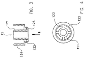
- Fig.3 is a side elevation in a cross-section of the compressing piston.
- Fig.4 is the view of the compressing piston in direction of arrow A of Fig. 3.
- Fig.2 shows a membrane keyswitch embodying the present invention.
- This keyswitch includes a housing 13, a button 11, a compressing piston 12, and a rubber element 14.
- Said housing 13 has an opening end placed on top of a membrane switch 15, and approximately the central position of the other end of said housing has a first opening and at least a pair of second openings.
- About the central position of the internal surface of said button 11 has a connector 16.
- Said compressing piston 12 has a cylindrical shape comprising a main vertical guider 121 in its center.
- Said guider 121 provides a guiding track for the insertion of the connector 16.
- Said compressing piston 12 has a supporting ring 122 which shares the same axis as that of the main vertical guider 121.
- Said supporting ring 122 links to the main vertical guider 121 by rib elements 123.
- On the external surface of the supporting ring 122 along the rim of the guider 121 there exists at least a pair of the suspending guiding
- the rubber element 14 is located in the space within the housing 13 and placed on top of the membrane switch 15.
- a support member 141 of the rubber element 14 is provided for installing the connecting ring 122 on top.
- This keyswitch requires to install the rubber element 14 on a printed circuit board first, set the compressing piston 12 on the support member 141 of the rubber element 14, and then lay the supporting ring 122 on the support member 141.
- the first opening end and the second opening end of the housing 13 superimpose on and passing through the main vertical guider 121 and the guiding arms respectively.
- the connector 16 of the button 11 is inserted into the channel of the main vertical guider to complete the whole assembly process.
- the contact position of the support member 141 and the compressing piston is not exactly at the central position of the housing, but at either side of the interior within housing.
- the button When the button is depressed, its displacement will not be affected by the rubber element 14. A maximum displacement can be achieved.
- the support member 141 is closer to the internal wall of the housing 13, its span is larger and results in a more steady displacement without tilting the keyswitch.
Landscapes
- Push-Button Switches (AREA)
Description
- The present invention relates generally to the field of a keyboard keyswitch assembly, and more particularly to a keyboard membrane keyswitch assembly of the kind comprising a housing, a compressing piston, a button and a rubber element. Said compressing piston comprises at least a pair of suspending guiding arms linked with the compressing piston's main vertical guider located at the central part of said compressing piston by at least a pair of the rib element and a connector. A guiding track on the main vertical guider is provided for the insertion of said connector. The rubber element is placed inside the housing and on top of the membrane switch. Said rubber element has a support member and said connector is placed on top of the support member; see e.g. DE-A-3 501 046.
- This invention relates to the switch of a notebook computer keyboard. With the advancement of technology, such as the announcement of power saving microprocessor, and the consumer's need, notebook computers become a popular product in the information market. Desktop computers are gradually replaced by the notebook computers.
- The membrane keyswitch is designed to provide the operator with a steady inputting mechanism, so that, when a keyswitch is depressed, the keyswitch maintains a steady position and will not tilt to one side. As a result, the keyboard is more convenient to use and minimizes fatigue. The membrane switch of this kind is also disclosed in the R.O.C. patent application number 80202928, where other variations of this keyswitch are detailed.
- The membrane keyswitch incorporated in notebook computers are quite different from those commonly used in other types of computers, since the notebook computers are more compact and smaller in size. The prior art usually has the connection of the support member of the
rubber element 24 and the compressingpiston 22 designed in the central position of the space inside the housing. When thebutton 23 is depressed, its displacement is limited by the existence of the rubber element. Furthermore, the assembly of this kind has a tendency to tilt when the button is depressed. - The principal function of the invention is to provide a novel keyswitch assembly, in which the displacement of the keyswitch is maximized, even with the existence of the rubber element within the housing of the keyswitch.
- The other function of the invention is to provide a keyswitch assembly, in which the button maintains in a steady position and will not tilt to one side, when the keyswitch is depressed.
- Fig.1 is a side elevation in a cross-section of an entire membrane keyswitch of the prior art, in which the keyswitch is not depressed.
- Fig.2 is a side elevation in a cross-section of an entire membrane keyswitch of the present invention, in which the keyswitch is not depressed.
- Fig.3 is a side elevation in a cross-section of the compressing piston.
- Fig.4 is the view of the compressing piston in direction of arrow A of Fig. 3.
- Fig.2 shows a membrane keyswitch embodying the present invention. This keyswitch includes a
housing 13, abutton 11, acompressing piston 12, and arubber element 14. Saidhousing 13 has an opening end placed on top of amembrane switch 15, and approximately the central position of the other end of said housing has a first opening and at least a pair of second openings. About the central position of the internal surface of saidbutton 11 has aconnector 16. Said compressingpiston 12 has a cylindrical shape comprising a mainvertical guider 121 in its center. Saidguider 121 provides a guiding track for the insertion of theconnector 16. Said compressingpiston 12 has a supportingring 122 which shares the same axis as that of the mainvertical guider 121. Said supportingring 122 links to the mainvertical guider 121 byrib elements 123. On the external surface of the supportingring 122 along the rim of theguider 121, there exists at least a pair of the suspending guidingarms 124. - The
rubber element 14 is located in the space within thehousing 13 and placed on top of themembrane switch 15. Asupport member 141 of therubber element 14 is provided for installing the connectingring 122 on top. - The assembly of this keyswitch requires to install the
rubber element 14 on a printed circuit board first, set thecompressing piston 12 on thesupport member 141 of therubber element 14, and then lay the supportingring 122 on thesupport member 141. The first opening end and the second opening end of thehousing 13 superimpose on and passing through the mainvertical guider 121 and the guiding arms respectively. Finally theconnector 16 of thebutton 11 is inserted into the channel of the main vertical guider to complete the whole assembly process. - As shown on Fig.2, the contact position of the
support member 141 and the compressing piston is not exactly at the central position of the housing, but at either side of the interior within housing. When the button is depressed, its displacement will not be affected by therubber element 14. A maximum displacement can be achieved. Furthermore, since thesupport member 141 is closer to the internal wall of thehousing 13, its span is larger and results in a more steady displacement without tilting the keyswitch.
Claims (2)
- A keyswitch assembly comprising:(a) a housing (13) adapted to be positioned on a membrane switch (15), said housing having an opening end on its top surface, a first opening approximately located at the central position of its bottom surface, and at least a pair of second openings;(b) a button (11), said button having a connector (16) located approximately at the central position of the interior of said button;(c) a compressing piston (12) having a main vertical guider (121) and a supporting ring (122), a guiding track being provided approximately at the central part of said compressing piston (12), said supporting ring (122) being connected to said main vertical guider (121) through at least a pair of rib elements (123) and at least a pair of suspending guiding arms (124) extending along the external surface of said main vertical guider;(d) an elastic member (14) adapted to be positioned inside of said housing (13) and on said membrane switch (15), said elastic member having a support member (141), on which said supporting ring (122) is placed; wherein said compressing piston (12) and said elastic member (14) are placed in the internal space of said housing (13), said main vertical guider (121) passes through said first opening of said housing (13), the guiding track of said main vertical guider (121) serves for the insertion of said connector (16), said guiding arms (124) pass through said second opening of said housing (13), and said compressing piston (12) travels back and forth along said first opening and said second opening by the force asserted on the piston by user's operation and the elasticity of said elastic member (14).
- The keyswitch assembly recited in claim 1, wherein the elastic member is made of rubber.
Priority Applications (1)
| Application Number | Priority Date | Filing Date | Title |
|---|---|---|---|
| DE1992610207 DE69210207T2 (en) | 1992-02-07 | 1992-02-07 | Membrane keyboard and key switch structure |
Applications Claiming Priority (1)
| Application Number | Priority Date | Filing Date | Title |
|---|---|---|---|
| US07/830,173 US5215187A (en) | 1992-01-31 | 1992-01-31 | Keyboard membrane keyswitch assembly |
Publications (2)
| Publication Number | Publication Date |
|---|---|
| EP0554493A1 EP0554493A1 (en) | 1993-08-11 |
| EP0554493B1 true EP0554493B1 (en) | 1996-04-24 |
Family
ID=25256467
Family Applications (1)
| Application Number | Title | Priority Date | Filing Date |
|---|---|---|---|
| EP92102092A Expired - Lifetime EP0554493B1 (en) | 1992-01-31 | 1992-02-07 | A keyboard membrane keyswitch assembly |
Country Status (3)
| Country | Link |
|---|---|
| US (1) | US5215187A (en) |
| EP (1) | EP0554493B1 (en) |
| MY (1) | MY109805A (en) |
Families Citing this family (9)
| Publication number | Priority date | Publication date | Assignee | Title |
|---|---|---|---|---|
| US5456541A (en) * | 1994-03-23 | 1995-10-10 | Ching-Shui; Liao | Key unit of a keyboard |
| JP2699936B2 (en) * | 1995-06-06 | 1998-01-19 | 日本電気株式会社 | Method for producing composite molded body |
| US5717429A (en) * | 1996-04-03 | 1998-02-10 | Texas Instruments Incorporated | Low profile, light weight keyboard |
| US5812116A (en) * | 1996-05-30 | 1998-09-22 | Texas Instruments Incorporated | Low profile keyboard |
| JP3456111B2 (en) * | 1997-05-29 | 2003-10-14 | 松下電器産業株式会社 | Push button switch and method of manufacturing the same |
| US6156986A (en) * | 1999-12-30 | 2000-12-05 | Jing Mold Enterprise Co., Ltd. | Computer key switch |
| US6781077B2 (en) | 2000-12-14 | 2004-08-24 | Think Outside, Inc. | Keyswitch and actuator structure |
| JP4534736B2 (en) * | 2004-11-30 | 2010-09-01 | ブラザー工業株式会社 | Information device |
| TWM354115U (en) * | 2008-09-26 | 2009-04-01 | Darfon Electronics Corp | Keyboard structure |
Family Cites Families (10)
| Publication number | Priority date | Publication date | Assignee | Title |
|---|---|---|---|---|
| US3856998A (en) * | 1973-06-01 | 1974-12-24 | Burroughs Corp | Keyboard switch assembly with improved operating means |
| US4440992A (en) * | 1982-03-03 | 1984-04-03 | Amp Incorporated | Low profile keyboard switch actuating assembly |
| DE8401137U1 (en) * | 1984-01-17 | 1984-05-03 | Deutsche Fernsprecher Gesellschaft Mbh Marburg, 3550 Marburg | Key, in particular for keypad keypads on telephones |
| US4827243A (en) * | 1987-11-23 | 1989-05-02 | Cheng Sheng Chuang | Improved structure of computer keyboard and circuit board |
| JPH01264125A (en) * | 1988-04-13 | 1989-10-20 | Brother Ind Ltd | press key switch |
| JPH0770272B2 (en) * | 1989-07-26 | 1995-07-31 | 富士通株式会社 | Push button switch |
| JPH03108218A (en) * | 1989-09-21 | 1991-05-08 | Fujitsu Ltd | Push button switch |
| JPH03119620A (en) * | 1989-10-02 | 1991-05-22 | Matsushita Electric Ind Co Ltd | Push button switch |
| US5120923A (en) * | 1989-10-06 | 1992-06-09 | Takafumi Kato | Push button switch |
| DE3939724A1 (en) * | 1989-11-16 | 1991-06-06 | Juelich Werner | Key field for keyboard with keys associated with carrier plate - having cap and pressure elements protruding through giving improved sealing and simplified prodn. |
-
1992
- 1992-01-31 US US07/830,173 patent/US5215187A/en not_active Expired - Lifetime
- 1992-02-07 EP EP92102092A patent/EP0554493B1/en not_active Expired - Lifetime
- 1992-03-18 MY MYPI92000442A patent/MY109805A/en unknown
Also Published As
| Publication number | Publication date |
|---|---|
| MY109805A (en) | 1997-07-31 |
| US5215187A (en) | 1993-06-01 |
| EP0554493A1 (en) | 1993-08-11 |
Similar Documents
| Publication | Publication Date | Title |
|---|---|---|
| KR100281537B1 (en) | Handheld Computers with Frames for Mounting Multiple Devices | |
| US4703160A (en) | Casing structure of portable electronic appliance | |
| US5582470A (en) | Scanner housing | |
| US6281887B1 (en) | Touchpad assembly | |
| US6147858A (en) | Keyboard unit and portable type information apparatus having the same | |
| EP0543649B1 (en) | Keyswitch assembly | |
| KR0176645B1 (en) | Laptop personal computer connectivity to expand functionality | |
| JPH1153983A (en) | Key switch assembly for multiple width key | |
| US5145058A (en) | Notebook computer key | |
| EP0554493A1 (en) | A keyboard membrane keyswitch assembly | |
| CN218887033U (en) | Multi-directional input device | |
| KR20000011644U (en) | Portable computer with speakers | |
| JPH10283883A (en) | Switch structure of electronic apparatus | |
| US6393165B1 (en) | Touch pad module for controlling a cursor | |
| KR20010049151A (en) | Connecting device | |
| KR100252252B1 (en) | Apparatus fpr preventing electromagnetic interference of between portable computer and extension system | |
| KR20050107524A (en) | Adjustable detachable keyboard and electronic assembly using same | |
| US6056459A (en) | Balance device for key | |
| US7355136B2 (en) | Button device for computer bezel | |
| US6376778B1 (en) | Printed circuit board assembly | |
| EP4325822B1 (en) | Button structure and electronic device | |
| KR100284301B1 (en) | Expansion system of portable computer with variable guide device | |
| CN112840427A (en) | Push-type input device and push-and-rotate input device | |
| KR200222485Y1 (en) | Switch for kryboard | |
| US5917474A (en) | Free pivot-arm key plate |
Legal Events
| Date | Code | Title | Description |
|---|---|---|---|
| PUAI | Public reference made under article 153(3) epc to a published international application that has entered the european phase |
Free format text: ORIGINAL CODE: 0009012 |
|
| AK | Designated contracting states |
Kind code of ref document: A1 Designated state(s): DE FR |
|
| 17P | Request for examination filed |
Effective date: 19931104 |
|
| 17Q | First examination report despatched |
Effective date: 19950705 |
|
| GRAH | Despatch of communication of intention to grant a patent |
Free format text: ORIGINAL CODE: EPIDOS IGRA |
|
| RAP1 | Party data changed (applicant data changed or rights of an application transferred) |
Owner name: ACER PERIPHERALS, INC. |
|
| GRAA | (expected) grant |
Free format text: ORIGINAL CODE: 0009210 |
|
| AK | Designated contracting states |
Kind code of ref document: B1 Designated state(s): DE FR |
|
| REF | Corresponds to: |
Ref document number: 69210207 Country of ref document: DE Date of ref document: 19960530 |
|
| ET | Fr: translation filed | ||
| PLBE | No opposition filed within time limit |
Free format text: ORIGINAL CODE: 0009261 |
|
| STAA | Information on the status of an ep patent application or granted ep patent |
Free format text: STATUS: NO OPPOSITION FILED WITHIN TIME LIMIT |
|
| 26N | No opposition filed | ||
| PGFP | Annual fee paid to national office [announced via postgrant information from national office to epo] |
Ref country code: FR Payment date: 20040219 Year of fee payment: 13 |
|
| PGFP | Annual fee paid to national office [announced via postgrant information from national office to epo] |
Ref country code: DE Payment date: 20040331 Year of fee payment: 13 |
|
| PG25 | Lapsed in a contracting state [announced via postgrant information from national office to epo] |
Ref country code: DE Free format text: LAPSE BECAUSE OF NON-PAYMENT OF DUE FEES Effective date: 20050901 |
|
| PG25 | Lapsed in a contracting state [announced via postgrant information from national office to epo] |
Ref country code: FR Free format text: LAPSE BECAUSE OF NON-PAYMENT OF DUE FEES Effective date: 20051031 |
|
| REG | Reference to a national code |
Ref country code: FR Ref legal event code: ST Effective date: 20051031 |