EP0553336B1 - Trap por catching mice and rats - Google Patents
Trap por catching mice and rats Download PDFInfo
- Publication number
- EP0553336B1 EP0553336B1 EP92918193A EP92918193A EP0553336B1 EP 0553336 B1 EP0553336 B1 EP 0553336B1 EP 92918193 A EP92918193 A EP 92918193A EP 92918193 A EP92918193 A EP 92918193A EP 0553336 B1 EP0553336 B1 EP 0553336B1
- Authority
- EP
- European Patent Office
- Prior art keywords
- housing
- housing portion
- mouse
- mousetrap
- trap
- Prior art date
- Legal status (The legal status is an assumption and is not a legal conclusion. Google has not performed a legal analysis and makes no representation as to the accuracy of the status listed.)
- Expired - Lifetime
Links
Images

Classifications
-
- A—HUMAN NECESSITIES
- A01—AGRICULTURE; FORESTRY; ANIMAL HUSBANDRY; HUNTING; TRAPPING; FISHING
- A01M—CATCHING, TRAPPING OR SCARING OF ANIMALS; APPARATUS FOR THE DESTRUCTION OF NOXIOUS ANIMALS OR NOXIOUS PLANTS
- A01M23/00—Traps for animals
- A01M23/24—Spring traps, e.g. jaw or like spring traps
- A01M23/30—Break-back traps, i.e. mouse-trap type
Definitions
- the invention relates to traps for catching mice and rats. More particularly, this invention relates to traps for catching mice and rats which include trap mechanisms in combination with housings enclosing the trap mechanisms.
- mice and rats are ubiquitous creatures who have plagued centuries since humans began storing food millennia ago. The rodents' intelligence at times appears to approach our own, while their reproductive rate far exceeds ours. As man has proliferated so have mice and rats. It is estimated that they currently consume or contaminate $2,000,000,000 worth of grain a year in the United States alone. While our efforts to control their numbers at grain storage facilities have had only marginal success, we have been able to achieve a degree of success in our dwellings by using the conventional mouse trap exemplified in patents such as expired U.S. Patent Nos. 1,464,559 and 1,250,022.
- Such conventional mousetraps include a spring-biased striking element comprising a striker bar which is retained in a cocked position by a trigger member.
- the trigger member has bait placed thereon, or disposed proximate thereto, so that a mouse or rat attracted to the bait trips the trigger member, releasing the striker bar which under the influence of a powerful coil spring dispatches the mouse or rat within microseconds.
- mice and rats have been unable to resist bait placed on these traps.
- the patent literature includes a host of mousetraps and numerous mousetraps which utilise housings in combination with trapping mechanisms.
- US Patent No.2,059,937 which issued to Ellis in 1936.
- Ellis discloses a semicircular housing formed by a bottom, sides and a semicircular housing cover.
- an ordinary mousetrap having a base and a spring actuated striker bar.
- the spring element is retained by a latch when in the cocked position. It is moved to the cocked position by a lever pivoted to the outside of the housing and having a portion projecting through an arcade slot in the side wall of the housing to engage the striker bar.
- GB-A-555429 describes a mousetrap comprising a base portion and a cover portion removably mounted on the cover portion. A mousetrap mechanism is retained on the base portion. Access to the trap mechanism is provided by removal of the cover portion.
- a housing for containing a mousetrap mechanism comprising:
- a mousetrap comprising in combination, a mousetrap mechanism and housing within which the mousetrap mechanism is positioned:
- a deceased mouse can be removed from the trap by rotating the spring-biased striking element slightly toward the cocked position to release the mouse while the second housing portion is pivoted with respect to the first housing portion to open the housing so that the mouse can drop out.
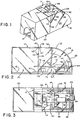
- the mousetrap housing 14 may be opaque ( Figure 1), transparent or translucent ( Figures 2-5 and 9).
- the mousetrap housing 14 comprises a base 16 to which is fixed a first housing portion designated generally by the numeral 18, which, as is seen in Figures 2 and 3, overlies a substantial portion of the mousetrap mechanism 12.
- Pivoted to the first housing portion 18 is a second housing portion, designated generally by the numeral 20, having an opening 22 therein through which the mouse enters.
- the first and second housing portions 18 and 20 co-operate with the base 16 to substantially completely enclose the mousetrap mechanism 12.
- the first housing portion 18 has side walls 24 and 26 with arcuate upper edges 28 and 29 and straight upper edges 30 and 31 which are spanned by a top wall 32 having an arcuate portion 34 overlying the arcuate edges and a straight portion 36 overlying the straight upper edges.
- the second housing portion 20 is connected to the first housing portion 18 by a flexible hinge 38 (which may be integral or unitary with the housing portions) to pivot about a line 40 at the front edge 42 of the straight portion 36 of top wall 32.
- the hinge 38 is moulded unitary with the housing portions 18 and 20.
- the second housing portion 20 includes rear side edges 44 and 46 and a top edge 47, which edges abut front edges 48 and 50 and the top front edge 42 of the first housing portion 18, shown in Figures 1-8, when in a first position in which the housing 14 is closed.
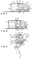
- the second housing portion pivots from a first position shown in Figures 1-8 to a second position shown in Figure 9. While in the second position, the trap mechanism 12 is exposed for both baiting and disposing of dead mice.
- the trap mechanism 12 comprises a base plate 60 which is fixed to the base 16 of the housing 14. Alternatively, the trap mechanism could be moulded into the base.
- the base plate 60 includes a pair of flanges 62 to which is pivoted a spring-biased striking element, designated generally by the numeral 64.
- the spring-biased striking element 64 includes a U-shaped striking bar 66 and a U-shaped cocking bar 68 which are fixed at an angle ⁇ with respect to one another to form a relatively rigid unit.
- a coil-spring 70 biases the striking element 64 to rotate about pivot 72 from the cocked position shown in solid lines Figures 1-7 to the uncocked or striking position shown in Figure 8 (and in dotted lines in Figures 2 and 6) wherein the striker bar 66 pivots into proximity with a trigger plate 74.
- the trigger plate 74 is also pivoted on the base plate 60 of the trap mechanism 12 and preferably is copivoted on the pivot 72 with the coil spring 70 and striking element 64.
- a bait holder 76 is positioned in alignment with an opening 78 through the trigger member 74 so that a mouse in attempting to eat the bait in the bait holder 76 depresses the trigger member to release the cocking bar 68 from retention by a hook 80 held in retention with the cocking bar by the trigger member.
- the bait can be placed directly on the trigger member 74.
- mousetrap 12 described thus far may have a configuration similar to United States Patents 2,517,928; 2,616,211, each of which includes a spring biased striking element comprising a striker bar and cocking bar rigidly disposed at an angle with respect to one another.
- the cocking bar 68 has a tab 84 rigidly associated therewith and projecting therefrom through a slot 86 in the arcuate portion 34 of the upper wall 32 enclosing the top and rear of the first housing 18.
- the tab 84 allows one to set the trap by engaging the tab with one's finger to rotate the cocking bar 68 in a clockwise direction about the pivot 72 from the uncocked dotted line position shown in Figures 2 and 6 to the solid line position shown in Figures 2 and 6 in which the hook 80 retains the cocking bar, and thus the striking element 64, in the cocked position with the striking bar 66 raised above the trigger member 74.
- a mouse unacquainted with the lethal nature of the trap mechanism 12, enters the housing 14 through the opening 22. In its desire to consume the bait the mouse steps on the trigger member 74. This releases the striking element 64 from retention by the hook 80. Within microseconds the striking bar 68 dispatches the mouse. The mouse's demise takes place within the enclosed housing 14 which, in accordance with one embodiment of the invention, may be made of an opaque plastic material so that the person using the trap 10 need not be overly familiar with its consequences.
- the trap 10 may be emptied without the person using it touching or running the risk of touching the dead mouse.
- the tab 84 is rotated clockwise, sufficient to lift the striker bar 66 from the dead mouse. Since the second housing portion 20 is freely pivoted by hinge 40 to the top of the first housing portion 18, it will pivot about pivot line 40, and rotate away from the first housing portion when the base 16 is oriented vertically. Consequently, the deceased mouse can drop away from the trap 10 into the trash can without the person having to touch the mouse or even look at it.
- the trap may then be rebaited with the striking element 64 in the dotted line position of Figure 6 and thereafter reset by rotating the tab 84 from the dotted line position to the solid line position of Figure 6.
Landscapes
- Life Sciences & Earth Sciences (AREA)
- Pest Control & Pesticides (AREA)
- Engineering & Computer Science (AREA)
- Insects & Arthropods (AREA)
- Wood Science & Technology (AREA)
- Zoology (AREA)
- Environmental Sciences (AREA)
- Catching Or Destruction (AREA)
- Position Input By Displaying (AREA)
- Peptides Or Proteins (AREA)
Description
Claims (17)
- A housing (14,18,20) for containing a mousetrap mechanism, the housing comprising:a base(16)for supporting the mousetrap mechanism(12);a first housing portion(18)fixed to the base(16)and overlying at least a portion of the mousetrap mechanism(12), the first housing portion(18)having a slot(86)therein through which the mousetrap mechanism is accessed for cocking the mousetrap mechanism;a second housing portion(20)having an opening(22) there through through which a mouse can enter, andmeans(38)for movably mounting the second housing portion(20)with respect to both the first housing portion(18)and base (16), wherein the second housing portion(20)is selectively movable from a first position in which the mousetrap mechanism is completely shielded to the second position in which the housing opens for disposal of a mouse caught therein, said disposal being effected by movement of a cocking mechanism projecting through said slot (86).
- The housing of claim 1 wherein the first housing portion(18)and second housing portion(20)have top walls(32)spaced from the base and wherein the second housing portion is pivoted with respect to the first housing portion along a pivot line(40)where the top walls of the housing portions meet.
- The housing of claim 2 wherein the slot(86)in the first housing portion is in the top wall(32)thereof and wherein a tab(84)on the mousetrap mechanism(12)extends through the slot(86)for cocking the mousetrap mechanism.
- The housing of claim 2 or 3 wherein the first housing portion(18)includes side walls (24,26) with an arcade upper edge whereby the top wall(32)has an arcade surface(34)in which the slot(86)is formed.
- The housing of claim 2, 3 or 4 wherein the second housing portion(20)freely abuts the first housing portion(18)and base(16)so as to swing open freely about the pivot line(40)to allow the deceased mouse to drop from the housing when released by the trap mechanism(12).
- The housing(14)as claimed in any of claims 1 to 5, wherein the housing is made of an opaque material.
- The housing(14)as claimed in any of claims 1 to 5, wherein the housing is made of transparent material.
- The housing(14)as claimed in any of claims 1 to 5, wherein the housing is made of translucent material.
- A mousetrap comprising in combination, a mousetrap mechanism(12)and housing(14)within which the mousetrap mechanism is positioned:the mousetrap mechanism(12)comprising:a spring-biased striking element(64)comprising a striker bar(66)and a cocking bar(68), the cocking bar projecting at an angle with respect to the striker bar, anda trigger member(74)positioned proximate the striking element(64)and being disposed in proximity with a bait holder(76);and the housing(14)comprising:a base(16);a first housing portion(18)attached to the base(16) and enclosing a portion of the mousetrap mechanism(12), the first housing portion(18)having a slot(86)therein through which a portion(84)of the cocking bar(68)extends for cocking the mousetrap by a force applied external to the housing;a second housing portion(20)having a hole(22)therein through which a mouse can enter the housing; andmeans(38)for mounting the second housing portion(20) for movement with respect to the first housing portion(18)and the base (16), whereby the second housing portion(20)moves from a first position, in which the second housing portion(20)co-operates with the first housing portion(18)to completely enclose the mousetrap mechanism(12)with the opening(22)of the second housing portion(20)positioned adjacent to the trigger member(74), to a second position in which a portion of the base(16) proximate the trigger member(74)is exposed, whereby a deceased mouse can be removed from the trap by rotating the striker bar(66)toward the cocked position before or while the second housing portion(20)is in the second position.
- A mouse trap as claimed in claim 9, wherein the first housing portion(18)and second housing portion(20)have top walls(32)spaced from the base and wherein the second housing portion(20)is pivoted to the first housing portion(18)along a pivot line(40)where the top walls(32) of the housing portions meet.
- A mouse trap as claimed in claim 10, wherein the slot(86)in the first housing portion(18)is in the top wall(32)thereof and wherein a tab(84)on the mousetrap mechanism(12)extends through the slot (86) for cocking the mousetrap mechanism (12).
- A mouse trap as claimed in claim 10 or 11 wherein the first housing portion(18)includes side walls(24,26)with an arcade upper edge(34)whereby the top wall(32)has an arcade surface in which the arcade slot(86)is formed.
- A mouse trap as claimed in claim 10,11 or 12 wherein the second housing portion(20)freely abuts the first housing portion(18)and base(16)so as to swing open freely about the pivot line(40)to allow the deceased mouse to drop from the housing when released by the trap mechanism.
- A mouse trap as claimed in any of claims 9 to 13, wherein the housing(14)is made of an opaque material.
- A mouse trap as claimed in any of claims 9 to 13, wherein the housing (14) is made of a transparent material.
- A mouse trap as claimed in any of claims 9 to 13, wherein the housing(14)is made of a translucent material.
- A mousetrap comprising:a trap mechanism(12)comprising a striker bar(66); a cocking mechanism(68)for positioning the striker bar; means(80)for releasably holding the striker bar in a cocked position; and trigger means(74)for releasing the striker bar(66)from the cocked position upon being disturbed by a mouse; anda housing(14)for containing the trap mechanism(12), the housing(14)having;a first part (18) and a second part (20);an opening(86)therein through which a portion(84)of the cocking mechanism(12)projects for cocking the trap mechanism before trapping and for releasing a trapped mouse after trapping while said housing(14)generally shields from view most of the trap mechanism(12)and any trapped mouse;an opening(22)therein through which the mouse enters, and wherein the first housing part (18) and the second housing part (20) are hinged to one another to provide means(38)for opening the housing(14)to expose the trap for both baiting the trap and releasing a trapped mouse therefrom.
Applications Claiming Priority (3)
| Application Number | Priority Date | Filing Date | Title |
|---|---|---|---|
| US07/747,161 US5172512A (en) | 1991-08-19 | 1991-08-19 | Trap for catching mice and rats |
| US747161 | 1991-08-19 | ||
| PCT/US1992/006783 WO1993003612A1 (en) | 1991-08-19 | 1992-08-10 | Trap por catching mice and rats |
Publications (2)
| Publication Number | Publication Date |
|---|---|
| EP0553336A1 EP0553336A1 (en) | 1993-08-04 |
| EP0553336B1 true EP0553336B1 (en) | 1998-01-21 |
Family
ID=25003910
Family Applications (1)
| Application Number | Title | Priority Date | Filing Date |
|---|---|---|---|
| EP92918193A Expired - Lifetime EP0553336B1 (en) | 1991-08-19 | 1992-08-10 | Trap por catching mice and rats |
Country Status (8)
| Country | Link |
|---|---|
| US (1) | US5172512A (en) |
| EP (1) | EP0553336B1 (en) |
| KR (1) | KR930701911A (en) |
| AU (2) | AU666671B2 (en) |
| CA (1) | CA2092536C (en) |
| DE (1) | DE69224177T2 (en) |
| MX (1) | MX9204772A (en) |
| WO (1) | WO1993003612A1 (en) |
Cited By (7)
| Publication number | Priority date | Publication date | Assignee | Title |
|---|---|---|---|---|
| USD577412S1 (en) | 2008-06-16 | 2008-09-23 | Smg Brands, Inc. | Rodent trap |
| USD589583S1 (en) | 2007-12-14 | 2009-03-31 | Smg Brands, Inc. | Rodent trap |
| USD589584S1 (en) | 2008-05-29 | 2009-03-31 | Smg Brands, Inc. | Rodent trap |
| US8490323B2 (en) | 2007-12-14 | 2013-07-23 | Oms Investments, Inc. | Rodent trap having a pivoting platform |
| US20140230312A1 (en) * | 2011-09-02 | 2014-08-21 | Swissinno Solutions Ag | Snap trap |
| US11252952B2 (en) | 2017-01-10 | 2022-02-22 | Oms Investments, Inc. | Rodent trap having a pivoting platform |
| USD956170S1 (en) | 2017-01-10 | 2022-06-28 | Oms Investments, Inc. | Rodent trap |
Families Citing this family (47)
| Publication number | Priority date | Publication date | Assignee | Title |
|---|---|---|---|---|
| NO176382C (en) * | 1992-11-25 | 1995-03-29 | Hallgeir Hovden | Catch trap device |
| US5746736A (en) * | 1995-08-09 | 1998-05-05 | Lumedics, Ltd. | Cryogenic laser lithotripsy with enhanced light absorption |
| US6199314B1 (en) * | 1999-07-23 | 2001-03-13 | Everett B. Ballard | Mouse trap cocking device |
| GB0325446D0 (en) * | 2003-10-31 | 2003-12-03 | Reckitt Benckiser Au Pty Ltd | Mousetrap |
| GB0402717D0 (en) * | 2004-02-05 | 2004-03-10 | Network Pest Control Systems L | Pest control apparatus |
| SE527605C2 (en) * | 2004-04-14 | 2006-04-25 | Per Danielsson | Trap for animals |
| US20080236024A1 (en) * | 2007-03-27 | 2008-10-02 | Aurele Ouellette | Humane trap for animals |
| US7886479B2 (en) * | 2007-12-14 | 2011-02-15 | Smg Brands, Inc. | Rodent trap having compressive trapping members |
| US7814702B2 (en) * | 2007-12-14 | 2010-10-19 | Smg Brands, Inc. | Rodent trap having a pivoting platform |
| US7921593B2 (en) * | 2007-12-14 | 2011-04-12 | Smg Brands, Inc. | Rodent trap having a snare |
| US20090151223A1 (en) * | 2007-12-14 | 2009-06-18 | Philip Nathan | Rodent Trap Having A Pivoting Platform |
| US7607254B1 (en) * | 2008-05-30 | 2009-10-27 | Chang-Hsiu Huang | Mouse trap having a triggering plate |
| MX2011002959A (en) * | 2008-09-22 | 2011-04-26 | Basf Corp | Rodent management system. |
| US20100115824A1 (en) * | 2008-10-08 | 2010-05-13 | Steven Frisch | Rodent Snap Action Trap |
| US20100139150A1 (en) * | 2008-10-23 | 2010-06-10 | Bruce William Thomas | Animal trap and station |
| US7954275B2 (en) * | 2009-02-09 | 2011-06-07 | Ap&G Co., Inc. | Rodent trap with removable trigger plate |
| US8104222B2 (en) * | 2009-07-31 | 2012-01-31 | Hovey David C | Animal trap |
| US8695274B2 (en) * | 2009-09-24 | 2014-04-15 | Woodstream Corporation | Single use hermetically sealing mousetrap with internal carbon dioxide killing mechanism |
| US8291637B2 (en) * | 2009-09-25 | 2012-10-23 | B&G Equipment Company | Rodent trap including presence indicator mechanism |
| US8418396B2 (en) * | 2009-12-10 | 2013-04-16 | Frank Moustirats | Humane animal trap |
| USD673640S1 (en) | 2012-02-09 | 2013-01-01 | Reckitt & Colman (Overseas) Limited | Mousetrap |
| CH706417A1 (en) | 2012-04-18 | 2013-10-31 | Andermatt Biocontrol Ag | Catching device for above-ground and killing small mammals. |
| DK178531B1 (en) * | 2013-12-02 | 2016-06-06 | Wisecon As | Trap |
| JP6255286B2 (en) * | 2014-03-18 | 2017-12-27 | 株式会社イシダ | Distributed supply device and combination weighing device |
| US11044901B2 (en) * | 2015-12-08 | 2021-06-29 | Ap&G Co., Inc. | Dome-covered rodent trap |
| US20200178514A1 (en) * | 2016-05-27 | 2020-06-11 | David B Schurman | Snap Trap Sheild |
| USD896338S1 (en) * | 2016-11-08 | 2020-09-15 | Michael G. Hetman | Rodent trap funnel |
| US20180125056A1 (en) * | 2016-11-08 | 2018-05-10 | Michael G. Hetman | Rodent trap |
| CN106922645A (en) * | 2017-04-07 | 2017-07-07 | 王道林 | A kind of self-action speed lock quick open type mousetrap |
| TWI829924B (en) * | 2019-05-05 | 2024-01-21 | 喬爾S 馬克斯 | Easy set tunnel form animal trap |
| DK180462B1 (en) * | 2019-07-05 | 2021-05-06 | Anticimex Innovation Center As | Rodent trap |
| DK202070085A1 (en) * | 2020-02-14 | 2021-10-15 | Anticimex Innovation Center As | A rodent trap |
| US12193431B2 (en) | 2020-11-13 | 2025-01-14 | Sheng Han Tool Co., Ltd. | Trap |
| USD1004736S1 (en) * | 2021-02-03 | 2023-11-14 | Fumigation Service & Supply, Inc. | Mouse trap bracket |
| USD1039648S1 (en) * | 2021-05-05 | 2024-08-20 | Nickolas Rinne | Slide bucket lid mouse trap |
| US11445719B1 (en) * | 2021-06-29 | 2022-09-20 | Michael McGrade | Augmented rodent trap device and method of use |
| US20220408716A1 (en) * | 2021-06-29 | 2022-12-29 | Michael McGrade McGrade | Augmented rodent trap device and method of use |
| EP4366524A4 (en) * | 2021-07-09 | 2025-05-28 | Rewild Limited | KILLING TRAP FOR ANIMALS |
| KR102847391B1 (en) * | 2022-09-08 | 2025-08-19 | 주식회사 세스코 | Apparatus that for mouse catching |
| US20250089698A1 (en) * | 2023-09-15 | 2025-03-20 | David Schuelke | Detachable hood for rodent trap |
| USD1093539S1 (en) * | 2023-12-31 | 2025-09-16 | Julian Chambers | Rodent trap enclosure |
| US20250221396A1 (en) * | 2024-01-04 | 2025-07-10 | Vmip, Llc | Presence indicator mechanism for rodent trap |
| USD1038315S1 (en) * | 2024-01-25 | 2024-08-06 | Ruilian Zhou | Mouse trap |
| USD1042721S1 (en) * | 2024-04-15 | 2024-09-17 | Shenzhen Visson Technology Co., Ltd. | Mousetrap |
| US20260033480A1 (en) * | 2024-08-04 | 2026-02-05 | Vasile OROS | Hand-Held Rodent Trap Setting Devices |
| US20260033479A1 (en) * | 2024-08-04 | 2026-02-05 | Vasile OROS | Hand-Held Rodent Trap Setting Device |
| US12593833B2 (en) * | 2024-08-04 | 2026-04-07 | Vasile OROS | Hand-held rodent trap setting devices with trap retainer |
Family Cites Families (13)
| Publication number | Priority date | Publication date | Assignee | Title |
|---|---|---|---|---|
| US1275993A (en) * | 1918-06-15 | 1918-08-13 | Ernest L Spangler | Animal-trap. |
| DE358154C (en) * | 1920-11-27 | 1922-09-08 | Adolf Blaschke | Trap for mice u. Like. With a throwing device |
| US2059937A (en) * | 1935-04-10 | 1936-11-03 | Charles D Ellis | Trap |
| GB555429A (en) * | 1942-02-23 | 1943-08-23 | Frank Ernest Potter | Improvements in or relating to animal traps |
| US2416481A (en) * | 1944-05-29 | 1947-02-25 | Hollenbeck Eugene Grant | Animal trap |
| US2492957A (en) * | 1947-09-17 | 1950-01-03 | Joseph N Blair | Animal trap |
| US2525010A (en) * | 1948-02-06 | 1950-10-10 | Allison Wilson Mayne | Animal trap |
| US2544475A (en) * | 1949-11-28 | 1951-03-06 | William A Uttz | Mousetrap attachment |
| US2684553A (en) * | 1950-05-31 | 1954-07-27 | Emil F Schroeder | Rodent trap |
| US3992803A (en) * | 1975-03-20 | 1976-11-23 | Robert Dennis Kaiser | Mouse trap |
| US4341033A (en) * | 1980-01-19 | 1982-07-27 | Siegel David B | Releasing and resetting mechanism for use in a rat trap |
| US4607450A (en) * | 1984-11-20 | 1986-08-26 | Amcan, Inc. | Enclosed mousetrap having improved trap mechanism |
| FR2583617B1 (en) * | 1985-06-24 | 1988-04-22 | Guinoiseau Henri | DOUBLE INPUT TUNNEL TRAP FOR CAPTURING PESTS. |
-
1991
- 1991-08-19 US US07/747,161 patent/US5172512A/en not_active Expired - Lifetime
-
1992
- 1992-08-10 EP EP92918193A patent/EP0553336B1/en not_active Expired - Lifetime
- 1992-08-10 DE DE69224177T patent/DE69224177T2/en not_active Expired - Fee Related
- 1992-08-10 AU AU24686/92A patent/AU666671B2/en not_active Expired
- 1992-08-10 KR KR1019930701164A patent/KR930701911A/en not_active Withdrawn
- 1992-08-10 WO PCT/US1992/006783 patent/WO1993003612A1/en not_active Ceased
- 1992-08-10 CA CA002092536A patent/CA2092536C/en not_active Expired - Fee Related
- 1992-08-18 MX MX9204772A patent/MX9204772A/en not_active IP Right Cessation
-
1995
- 1995-12-22 AU AU40623/95A patent/AU673829B2/en not_active Expired
Cited By (7)
| Publication number | Priority date | Publication date | Assignee | Title |
|---|---|---|---|---|
| USD589583S1 (en) | 2007-12-14 | 2009-03-31 | Smg Brands, Inc. | Rodent trap |
| US8490323B2 (en) | 2007-12-14 | 2013-07-23 | Oms Investments, Inc. | Rodent trap having a pivoting platform |
| USD589584S1 (en) | 2008-05-29 | 2009-03-31 | Smg Brands, Inc. | Rodent trap |
| USD577412S1 (en) | 2008-06-16 | 2008-09-23 | Smg Brands, Inc. | Rodent trap |
| US20140230312A1 (en) * | 2011-09-02 | 2014-08-21 | Swissinno Solutions Ag | Snap trap |
| US11252952B2 (en) | 2017-01-10 | 2022-02-22 | Oms Investments, Inc. | Rodent trap having a pivoting platform |
| USD956170S1 (en) | 2017-01-10 | 2022-06-28 | Oms Investments, Inc. | Rodent trap |
Also Published As
| Publication number | Publication date |
|---|---|
| WO1993003612A1 (en) | 1993-03-04 |
| KR930701911A (en) | 1993-09-08 |
| CA2092536A1 (en) | 1993-02-20 |
| DE69224177T2 (en) | 1998-05-07 |
| CA2092536C (en) | 1998-09-29 |
| EP0553336A1 (en) | 1993-08-04 |
| DE69224177D1 (en) | 1998-02-26 |
| MX9204772A (en) | 1993-03-01 |
| AU673829B2 (en) | 1996-11-28 |
| AU2468692A (en) | 1993-03-16 |
| AU4062395A (en) | 1996-02-29 |
| AU666671B2 (en) | 1996-02-22 |
| US5172512A (en) | 1992-12-22 |
Similar Documents
| Publication | Publication Date | Title |
|---|---|---|
| US5172512A (en) | Trap for catching mice and rats | |
| CA1093301A (en) | Self-locking disposable rodent trap | |
| US8104222B2 (en) | Animal trap | |
| US4578892A (en) | Rodent trap | |
| US4607450A (en) | Enclosed mousetrap having improved trap mechanism | |
| US4569149A (en) | Disposable mouse trap | |
| US4127958A (en) | Mouse trap | |
| US5148624A (en) | Mousetrap | |
| US4748766A (en) | Animal trap | |
| US4703583A (en) | Baitless rodent trap | |
| US4912872A (en) | Live animal trap | |
| US4182070A (en) | Tamper-proof poisonous bait box | |
| US4768305A (en) | Animal trap | |
| US5809688A (en) | Reuseable rodent trap | |
| GB2173085A (en) | Rodent trap | |
| GB2230415A (en) | Disposable rodent trap | |
| US4335535A (en) | Rodent trap | |
| JP2021533836A (en) | Rodent capture device, system for replenishing rodent capture device, and method for replenishing rodent capture device | |
| GB2332356A (en) | Vermin trap | |
| WO2004030451A2 (en) | Rodent trap | |
| US7543406B2 (en) | Anti-false tripping escape-proof single-catch animal trap | |
| US4155193A (en) | Automatic all-purpose trap for catching small animals alive | |
| KR102284410B1 (en) | Rat Catcher | |
| US5325621A (en) | Animal trap | |
| CA1126511A (en) | Animal trap |
Legal Events
| Date | Code | Title | Description |
|---|---|---|---|
| PUAI | Public reference made under article 153(3) epc to a published international application that has entered the european phase |
Free format text: ORIGINAL CODE: 0009012 |
|
| 17P | Request for examination filed |
Effective date: 19930405 |
|
| AK | Designated contracting states |
Kind code of ref document: A1 Designated state(s): DE GB |
|
| 17Q | First examination report despatched |
Effective date: 19950523 |
|
| RAP1 | Party data changed (applicant data changed or rights of an application transferred) |
Owner name: RECKITT & COLMAN INC. |
|
| GRAG | Despatch of communication of intention to grant |
Free format text: ORIGINAL CODE: EPIDOS AGRA |
|
| GRAG | Despatch of communication of intention to grant |
Free format text: ORIGINAL CODE: EPIDOS AGRA |
|
| GRAH | Despatch of communication of intention to grant a patent |
Free format text: ORIGINAL CODE: EPIDOS IGRA |
|
| GRAH | Despatch of communication of intention to grant a patent |
Free format text: ORIGINAL CODE: EPIDOS IGRA |
|
| GRAA | (expected) grant |
Free format text: ORIGINAL CODE: 0009210 |
|
| AK | Designated contracting states |
Kind code of ref document: B1 Designated state(s): DE GB |
|
| REF | Corresponds to: |
Ref document number: 69224177 Country of ref document: DE Date of ref document: 19980226 |
|
| PLBE | No opposition filed within time limit |
Free format text: ORIGINAL CODE: 0009261 |
|
| 26N | No opposition filed | ||
| REG | Reference to a national code |
Ref country code: GB Ref legal event code: IF02 |
|
| PGFP | Annual fee paid to national office [announced via postgrant information from national office to epo] |
Ref country code: GB Payment date: 20050804 Year of fee payment: 14 |
|
| PGFP | Annual fee paid to national office [announced via postgrant information from national office to epo] |
Ref country code: DE Payment date: 20050930 Year of fee payment: 14 |
|
| PG25 | Lapsed in a contracting state [announced via postgrant information from national office to epo] |
Ref country code: DE Free format text: LAPSE BECAUSE OF NON-PAYMENT OF DUE FEES Effective date: 20070301 |
|
| GBPC | Gb: european patent ceased through non-payment of renewal fee |
Effective date: 20060810 |
|
| PG25 | Lapsed in a contracting state [announced via postgrant information from national office to epo] |
Ref country code: GB Free format text: LAPSE BECAUSE OF NON-PAYMENT OF DUE FEES Effective date: 20060810 |