EP0552403B1 - Winch handle - Google Patents
Winch handle Download PDFInfo
- Publication number
- EP0552403B1 EP0552403B1 EP19920111558 EP92111558A EP0552403B1 EP 0552403 B1 EP0552403 B1 EP 0552403B1 EP 19920111558 EP19920111558 EP 19920111558 EP 92111558 A EP92111558 A EP 92111558A EP 0552403 B1 EP0552403 B1 EP 0552403B1
- Authority
- EP
- European Patent Office
- Prior art keywords
- winch
- shaft
- crank
- handle
- knob
- Prior art date
- Legal status (The legal status is an assumption and is not a legal conclusion. Google has not performed a legal analysis and makes no representation as to the accuracy of the status listed.)
- Expired - Lifetime
Links
- 238000005452 bending Methods 0.000 description 2
- 230000006835 compression Effects 0.000 description 1
- 238000007906 compression Methods 0.000 description 1
- 238000010276 construction Methods 0.000 description 1
Images
Classifications
-
- B—PERFORMING OPERATIONS; TRANSPORTING
- B66—HOISTING; LIFTING; HAULING
- B66D—CAPSTANS; WINCHES; TACKLES, e.g. PULLEY BLOCKS; HOISTS
- B66D1/00—Rope, cable, or chain winding mechanisms; Capstans
- B66D1/60—Rope, cable, or chain winding mechanisms; Capstans adapted for special purposes
- B66D1/74—Capstans
- B66D1/7463—Accessories
- B66D1/7468—Handles
Definitions
- This invention relates to winch handles or hand cranks which are used to manually operate a winch or capstan.
- many larger sailboats utilize winches to provide a mechanical advantage in controlling lines such as a fairleads and halyards.
- the winch has a drive socket for releasably receiving a lug of the winch handle.
- the line is wrapped around the drum of the winch, and the winch contains gears to provide a mechanical advantage between the crank and the drive socket and drum.
- a conventional winch handle comprises an arm extending away from the rotational axis of the winch, and an upright shaft at the free end of the arm.
- a handle of generally tubular shape is rotatably mounted on the shaft. The crank s rotated by manually grasping the handle, with the palm of the hand being generally parallel to the axis of rotation of the handle and winch.
- Another conventional version currently in use comprises a pair of identical rotatable tubular handles mounted in succession on a common shaft. This permits two handed operation by one or two people. The latter type is used primarily for heavy load conditions because it is larger and more clumsy to use and store than the single handle version.
- winch handles are normally stowed in vertical pockets in the cockpit with the grip projecting at right angles at the top of the pocket.
- DE-A 26 35 267 discloses a winch crank comprising a tubular two part handle mounted on a shaft.
- the upper tubular part is fixed to the shaft.
- the lower tubular part is shiftable on the shaft against a compression spring to allow tilting of the handle to a storage and operating position.
- the upwardly facing portion is fixed to the shaft and is not adapted to be grasped with the palm of a hand perpendicular to the axis of the shaft.
- a two handed winch crank is provided with a conventional lower tubular handle and a separate shorter upper rotatable knob having an enlarged outwardly facing head.
- the lower handle is operated with the palm parallel to the axis of rotation, whereas the upper knob is operated with the palm facing downwardly or perpendicular to the axis of rotation.
- This allows for faster and more efficient cranking in comparison to conventional two handle cranks.
- the strength and weight of the arm and shaft may be less than conventional two handle versions because the reduced height or shaft length provides less bending moments on these parts.
- the crank of the present invention being reasonably compact and easy to use, can eliminate the need for having to carry two types of handles on a sailboat.
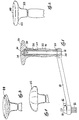
- Figure 1 is a side view, partly in section, of the winch crank of the present invention.
- Figure 2 is a perspective view of one version of the winch handles of the present invention.
- Figure 3 is a perspective view of a second configuration of the winch handles of the present invention.
- Figure 4 is a side view of another configuration of the winch handle.
- Figure 1 illustrates a winch cranking device comprising an elongated crank arm 10 having a faceted downwardly depending lug 12 secured at one end and adapted to drivingly engage a drive socket of a conventional winch (not shown) and to rotate the socket around a generally vertical axis in the orientation shown at 14.
- a conventional locking device 17 may be employed to releasably lock the lug 12 into the socket.
- crank arm 10 is angled slightly upward from horizontal from the lug end, with the free end of the arm having an upwardly extending or vertical shaft 16, which extends at right angles from the arm and is secured to the arm by means of securement of a lower portion 18 of the shaft 16 into an opening 20 in the arm.
- the axis of the shaft is generally parallel to the axis of rotation 14 at the winch.
- a lower, conventional handle 22 or grip of elongated tubular or barrel shape is rotatably mounted on the shaft 16 adjacent to the arm 10 by means of bearings, such as the upper 24 and lower 26 ball bearing races between the shaft and the respective ends of the handle.
- the upper or second handle 28 is in the form of a separate rotatable knob having a relatively enlarged head.
- the knob 28 is rotatably mounted on the free end of shaft 16 adjacent to the upper end of lower handle 22 by means of upper 30 and lower 32 ball bearing races.
- the knob 28 is restrained from upper axial movement by means of a washer 34 bearing downwardly on its outer periphery against the upper ball race, and having its central portion secured to the end of the shaft 16 by a bolt 36.
- the lower bearing race 32 may also hear on the top edge of the lower handle 22.
- the lower handle 22 is intended to be operated in a conventional fashion, with he palm of the hand extending parallel to the axis of rotation around the shaft.
- the upper, separately rotatable, knob 28 is designed and intended to be operated with the palm facing downwardly, or perpendicular to the axis of rotation, with the palm against or spaced from the upper rounded surface of the knob.
- Conventional two handle cranks cannot be operated in this fashion because there is a fixed end portion above the second handle.
- the upper knob 28 has a height or length which is substantially less than the height or length of the lower handle 22. This provides a more compact profile and provides reduced bending movements on the shaft and crank arm in comparison with conventional versions, allowing a lighter weight construction.
- knob 28 alone facilitates faster cranking, especially at lower loads or when the line is relatively slack.
- Two handed cranking is also facilitated, since the upper knob allows for a more efficient or compact form of movement between the hands and arms.
- the crank may be operated by the use of the handle or knob separately, or the use of both parts together.
- Figures 2, 3 and 4 illustrate two of the possible various configurations of the upper knob.
- the knob 28 may have a round or circular upper surface 40 with rounded sides 42. A round shape is easily grasped and facilitates palms down rapid turning of the crank handle.
- Figure 3 shows a rounded knob 44 having one or more ridges 44 to prevent slipping.
- Figures 4 shows a rounded knob 46 having an elongated T-shaped or oblong body, which is better adapted to fit between the palm and fingers of the hand.
Landscapes
- Engineering & Computer Science (AREA)
- Mechanical Engineering (AREA)
- Mechanically-Actuated Valves (AREA)
- Mechanical Control Devices (AREA)
- Rotary Switch, Piano Key Switch, And Lever Switch (AREA)
- Flexible Shafts (AREA)
Description
- This invention relates to winch handles or hand cranks which are used to manually operate a winch or capstan. For example, many larger sailboats utilize winches to provide a mechanical advantage in controlling lines such as a fairleads and halyards. The winch has a drive socket for releasably receiving a lug of the winch handle. The line is wrapped around the drum of the winch, and the winch contains gears to provide a mechanical advantage between the crank and the drive socket and drum.
- A conventional winch handle comprises an arm extending away from the rotational axis of the winch, and an upright shaft at the free end of the arm. A handle of generally tubular shape is rotatably mounted on the shaft. The crank s rotated by manually grasping the handle, with the palm of the hand being generally parallel to the axis of rotation of the handle and winch. Another conventional version currently in use comprises a pair of identical rotatable tubular handles mounted in succession on a common shaft. This permits two handed operation by one or two people. The latter type is used primarily for heavy load conditions because it is larger and more clumsy to use and store than the single handle version. In sailboats, winch handles are normally stowed in vertical pockets in the cockpit with the grip projecting at right angles at the top of the pocket.
- DE-A 26 35 267 discloses a winch crank comprising a tubular two part handle mounted on a shaft. The upper tubular part is fixed to the shaft. The lower tubular part is shiftable on the shaft against a compression spring to allow tilting of the handle to a storage and operating position. As in the case of conventional winch handles having two tubular parts, the upwardly facing portion is fixed to the shaft and is not adapted to be grasped with the palm of a hand perpendicular to the axis of the shaft.
- In accordance with the present invention, a two handed winch crank is provided with a conventional lower tubular handle and a separate shorter upper rotatable knob having an enlarged outwardly facing head. The lower handle is operated with the palm parallel to the axis of rotation, whereas the upper knob is operated with the palm facing downwardly or perpendicular to the axis of rotation. This allows for faster and more efficient cranking in comparison to conventional two handle cranks. Also, the strength and weight of the arm and shaft may be less than conventional two handle versions because the reduced height or shaft length provides less bending moments on these parts. Finally, the crank of the present invention, being reasonably compact and easy to use, can eliminate the need for having to carry two types of handles on a sailboat.
- Figure 1 is a side view, partly in section, of the winch crank of the present invention.
- Figure 2 is a perspective view of one version of the winch handles of the present invention.
- Figure 3 is a perspective view of a second configuration of the winch handles of the present invention.
- Figure 4 is a side view of another configuration of the winch handle.
- Figure 1 illustrates a winch cranking device comprising an
elongated crank arm 10 having a faceted downwardly dependinglug 12 secured at one end and adapted to drivingly engage a drive socket of a conventional winch (not shown) and to rotate the socket around a generally vertical axis in the orientation shown at 14. A conventional locking device 17 may be employed to releasably lock thelug 12 into the socket. - The
crank arm 10 is angled slightly upward from horizontal from the lug end, with the free end of the arm having an upwardly extending orvertical shaft 16, which extends at right angles from the arm and is secured to the arm by means of securement of alower portion 18 of theshaft 16 into an opening 20 in the arm. The axis of the shaft is generally parallel to the axis of rotation 14 at the winch. - A lower,
conventional handle 22 or grip of elongated tubular or barrel shape is rotatably mounted on theshaft 16 adjacent to thearm 10 by means of bearings, such as the upper 24 and lower 26 ball bearing races between the shaft and the respective ends of the handle. - In addition, and contrary to similar devices in the prior art, the upper or
second handle 28 is in the form of a separate rotatable knob having a relatively enlarged head. Theknob 28 is rotatably mounted on the free end ofshaft 16 adjacent to the upper end oflower handle 22 by means of upper 30 and lower 32 ball bearing races. Theknob 28 is restrained from upper axial movement by means of a washer 34 bearing downwardly on its outer periphery against the upper ball race, and having its central portion secured to the end of theshaft 16 by abolt 36. As shown, thelower bearing race 32 may also hear on the top edge of thelower handle 22. - The
lower handle 22 is intended to be operated in a conventional fashion, with he palm of the hand extending parallel to the axis of rotation around the shaft. In contrast, the upper, separately rotatable,knob 28 is designed and intended to be operated with the palm facing downwardly, or perpendicular to the axis of rotation, with the palm against or spaced from the upper rounded surface of the knob. Conventional two handle cranks cannot be operated in this fashion because there is a fixed end portion above the second handle. - It will be noted in Figure 1 that the
upper knob 28 has a height or length which is substantially less than the height or length of thelower handle 22. This provides a more compact profile and provides reduced bending movements on the shaft and crank arm in comparison with conventional versions, allowing a lighter weight construction. - In addition, the use of the
knob 28 alone facilitates faster cranking, especially at lower loads or when the line is relatively slack. Two handed cranking is also facilitated, since the upper knob allows for a more efficient or compact form of movement between the hands and arms. Thus, the crank may be operated by the use of the handle or knob separately, or the use of both parts together. - Figures 2, 3 and 4 illustrate two of the possible various configurations of the upper knob. As shown in Figure 2, the
knob 28 may have a round or circularupper surface 40 withrounded sides 42. A round shape is easily grasped and facilitates palms down rapid turning of the crank handle. Figure 3 shows arounded knob 44 having one ormore ridges 44 to prevent slipping. Figures 4 shows arounded knob 46 having an elongated T-shaped or oblong body, which is better adapted to fit between the palm and fingers of the hand.
Claims (5)
- A winch crank for rotating a winch mechanism around axis, in which the crank includes a crank arm, with one end of the arm being adapted for driving connection to the winch mechanism, and the other end having a shaft extending parallel to said axis toward a free end and having a tubular crank handle rotatably mounted on the shaft, characterized in that a separate knob having an enlarged head is rotatably mounted on the end of the shaft adjacent the tubular handle.
- The winch crank according to claim 1, characterized in that the knob is round.
- The winch crank according to claim 1, characterized in that the knob is oblong.
- The winch crank according to claim 1, characterized in that the length of the knob along the shalt is less than the length of the handle along the shaft.
- The winch crank according to claim 1, characterized in that the crank is operable with a hand grasping the tubular handle parallel to the axis of the shaft or with the palm of a hand grasping the knob perpendicular to the axis of the shaft.
Priority Applications (1)
| Application Number | Priority Date | Filing Date | Title |
|---|---|---|---|
| DE9218571U DE9218571U1 (en) | 1992-01-22 | 1992-07-08 | Winch handle |
Applications Claiming Priority (2)
| Application Number | Priority Date | Filing Date | Title |
|---|---|---|---|
| US82384692A | 1992-01-22 | 1992-01-22 | |
| US823846 | 1992-01-22 |
Publications (2)
| Publication Number | Publication Date |
|---|---|
| EP0552403A1 EP0552403A1 (en) | 1993-07-28 |
| EP0552403B1 true EP0552403B1 (en) | 1995-09-06 |
Family
ID=25239892
Family Applications (1)
| Application Number | Title | Priority Date | Filing Date |
|---|---|---|---|
| EP19920111558 Expired - Lifetime EP0552403B1 (en) | 1992-01-22 | 1992-07-08 | Winch handle |
Country Status (5)
| Country | Link |
|---|---|
| EP (1) | EP0552403B1 (en) |
| AU (1) | AU648900B2 (en) |
| DE (3) | DE552403T1 (en) |
| DK (1) | DK0552403T3 (en) |
| NZ (1) | NZ243185A (en) |
Family Cites Families (8)
| Publication number | Priority date | Publication date | Assignee | Title |
|---|---|---|---|---|
| FR906E (en) * | 1902-04-19 | 1903-04-23 | Bonnard Eugene | Motion transformation system |
| US3145974A (en) * | 1963-05-31 | 1964-08-25 | Thomas A Short | Deck winch |
| US3536299A (en) * | 1968-05-17 | 1970-10-27 | Robert A Mccloud | Winch mechanism |
| JPS56119087A (en) * | 1980-02-26 | 1981-09-18 | Nissan Motor | Regulator handle for window glass of automobile |
| GB2179011A (en) * | 1985-08-17 | 1987-02-25 | Peter Norman Cox | Two-handled crank for lock gates |
| US4674355A (en) * | 1985-09-20 | 1987-06-23 | Lear Siegler, Inc. | Crankhandle structure |
| US4883255A (en) * | 1988-02-01 | 1989-11-28 | Custom Products Corporation | Winch handle |
| US5255573A (en) * | 1992-01-22 | 1993-10-26 | Harken, Inc. | Winch handle |
-
1992
- 1992-06-17 AU AU18356/92A patent/AU648900B2/en not_active Ceased
- 1992-06-17 NZ NZ24318592A patent/NZ243185A/en not_active IP Right Cessation
- 1992-07-08 DE DE1992111558 patent/DE552403T1/en active Pending
- 1992-07-08 EP EP19920111558 patent/EP0552403B1/en not_active Expired - Lifetime
- 1992-07-08 DK DK92111558T patent/DK0552403T3/en active
- 1992-07-08 DE DE9218571U patent/DE9218571U1/en not_active Expired - Lifetime
- 1992-07-08 DE DE1992604648 patent/DE69204648T2/en not_active Expired - Fee Related
Also Published As
| Publication number | Publication date |
|---|---|
| DK0552403T3 (en) | 1995-11-06 |
| DE9218571U1 (en) | 1994-09-29 |
| DE69204648D1 (en) | 1995-10-12 |
| NZ243185A (en) | 1994-04-27 |
| DE69204648T2 (en) | 1996-03-21 |
| AU1835692A (en) | 1993-07-29 |
| DE552403T1 (en) | 1994-11-03 |
| EP0552403A1 (en) | 1993-07-28 |
| AU648900B2 (en) | 1994-05-05 |
Similar Documents
| Publication | Publication Date | Title |
|---|---|---|
| US5255573A (en) | Winch handle | |
| US5231727A (en) | Torsion handle polisher | |
| US4406186A (en) | Dual action ratchet wrench | |
| US4698032A (en) | Control unit for outboard marine motor assembly | |
| US4531715A (en) | Winch with storable handle | |
| US5511447A (en) | Automatic ratchet block | |
| US4225118A (en) | Direct drive deck winch | |
| US6638201B1 (en) | Cam action exercise apparatus with asymmetric energy management | |
| US4883255A (en) | Winch handle | |
| US7347403B2 (en) | Ice screw having breakaway or flexing crank handle | |
| US5833217A (en) | Detachable two-handed crank handle for nautical winch | |
| US6607340B2 (en) | Removable ice screw securing device equipped with a quickdraw | |
| US5471898A (en) | Breaker bar with 90 degree rotating socket connector head | |
| EP0759408B1 (en) | Winch with two speed ratio drum | |
| EP0552403A1 (en) | Winch handle | |
| US6406001B1 (en) | Chain lever hoist | |
| US6491285B1 (en) | Winch handle retention system | |
| CA1152362A (en) | Ratchet and gear drive socket wrench handle | |
| JPH0764518B2 (en) | Scissors jack | |
| US4517861A (en) | Continuous travel hand wrench | |
| JPS6312936Y2 (en) | ||
| US20240351509A1 (en) | Slip Grab Ratchet Binder | |
| US4391432A (en) | Winch operating handle | |
| CA1322132C (en) | Outboard motor tilt lock device | |
| US6099041A (en) | Body mounted sail assembly |
Legal Events
| Date | Code | Title | Description |
|---|---|---|---|
| PUAI | Public reference made under article 153(3) epc to a published international application that has entered the european phase |
Free format text: ORIGINAL CODE: 0009012 |
|
| AK | Designated contracting states |
Kind code of ref document: A1 Designated state(s): DE DK FR GB IT NL SE |
|
| 17P | Request for examination filed |
Effective date: 19930805 |
|
| DET | De: translation of patent claims | ||
| 17Q | First examination report despatched |
Effective date: 19941025 |
|
| GRAA | (expected) grant |
Free format text: ORIGINAL CODE: 0009210 |
|
| AK | Designated contracting states |
Kind code of ref document: B1 Designated state(s): DE DK FR GB IT NL SE |
|
| ITF | It: translation for a ep patent filed | ||
| REF | Corresponds to: |
Ref document number: 69204648 Country of ref document: DE Date of ref document: 19951012 |
|
| REG | Reference to a national code |
Ref country code: DK Ref legal event code: T3 |
|
| ET | Fr: translation filed | ||
| PLBE | No opposition filed within time limit |
Free format text: ORIGINAL CODE: 0009261 |
|
| STAA | Information on the status of an ep patent application or granted ep patent |
Free format text: STATUS: NO OPPOSITION FILED WITHIN TIME LIMIT |
|
| 26N | No opposition filed | ||
| PGFP | Annual fee paid to national office [announced via postgrant information from national office to epo] |
Ref country code: FR Payment date: 20010619 Year of fee payment: 10 |
|
| PGFP | Annual fee paid to national office [announced via postgrant information from national office to epo] |
Ref country code: SE Payment date: 20010620 Year of fee payment: 10 Ref country code: DE Payment date: 20010620 Year of fee payment: 10 |
|
| PGFP | Annual fee paid to national office [announced via postgrant information from national office to epo] |
Ref country code: NL Payment date: 20010621 Year of fee payment: 10 |
|
| PGFP | Annual fee paid to national office [announced via postgrant information from national office to epo] |
Ref country code: DK Payment date: 20010622 Year of fee payment: 10 |
|
| REG | Reference to a national code |
Ref country code: GB Ref legal event code: IF02 |
|
| PG25 | Lapsed in a contracting state [announced via postgrant information from national office to epo] |
Ref country code: SE Free format text: LAPSE BECAUSE OF NON-PAYMENT OF DUE FEES Effective date: 20020709 |
|
| PG25 | Lapsed in a contracting state [announced via postgrant information from national office to epo] |
Ref country code: DK Free format text: LAPSE BECAUSE OF NON-PAYMENT OF DUE FEES Effective date: 20020731 |
|
| PG25 | Lapsed in a contracting state [announced via postgrant information from national office to epo] |
Ref country code: DE Free format text: LAPSE BECAUSE OF NON-PAYMENT OF DUE FEES Effective date: 20030201 Ref country code: NL Free format text: LAPSE BECAUSE OF NON-PAYMENT OF DUE FEES Effective date: 20030201 |
|
| EUG | Se: european patent has lapsed | ||
| REG | Reference to a national code |
Ref country code: DK Ref legal event code: EBP |
|
| PG25 | Lapsed in a contracting state [announced via postgrant information from national office to epo] |
Ref country code: FR Free format text: LAPSE BECAUSE OF NON-PAYMENT OF DUE FEES Effective date: 20030331 |
|
| NLV4 | Nl: lapsed or anulled due to non-payment of the annual fee |
Effective date: 20030201 |
|
| REG | Reference to a national code |
Ref country code: FR Ref legal event code: ST |
|
| PGFP | Annual fee paid to national office [announced via postgrant information from national office to epo] |
Ref country code: IT Payment date: 20100723 Year of fee payment: 19 |
|
| PGFP | Annual fee paid to national office [announced via postgrant information from national office to epo] |
Ref country code: GB Payment date: 20100730 Year of fee payment: 19 |
|
| GBPC | Gb: european patent ceased through non-payment of renewal fee |
Effective date: 20110708 |
|
| PG25 | Lapsed in a contracting state [announced via postgrant information from national office to epo] |
Ref country code: IT Free format text: LAPSE BECAUSE OF NON-PAYMENT OF DUE FEES Effective date: 20110708 |
|
| PG25 | Lapsed in a contracting state [announced via postgrant information from national office to epo] |
Ref country code: GB Free format text: LAPSE BECAUSE OF NON-PAYMENT OF DUE FEES Effective date: 20110708 |