EP0551957B1 - Dispositif pour la traite d'animaux - Google Patents
Dispositif pour la traite d'animaux Download PDFInfo
- Publication number
- EP0551957B1 EP0551957B1 EP93200104A EP93200104A EP0551957B1 EP 0551957 B1 EP0551957 B1 EP 0551957B1 EP 93200104 A EP93200104 A EP 93200104A EP 93200104 A EP93200104 A EP 93200104A EP 0551957 B1 EP0551957 B1 EP 0551957B1
- Authority
- EP
- European Patent Office
- Prior art keywords
- milking
- animal
- implement
- teat
- robot
- Prior art date
- Legal status (The legal status is an assumption and is not a legal conclusion. Google has not performed a legal analysis and makes no representation as to the accuracy of the status listed.)
- Expired - Lifetime
Links
Images


Classifications
-
- A—HUMAN NECESSITIES
- A01—AGRICULTURE; FORESTRY; ANIMAL HUSBANDRY; HUNTING; TRAPPING; FISHING
- A01J—MANUFACTURE OF DAIRY PRODUCTS
- A01J5/00—Milking machines or devices
- A01J5/017—Automatic attaching or detaching of clusters
- A01J5/0175—Attaching of clusters
-
- A—HUMAN NECESSITIES
- A01—AGRICULTURE; FORESTRY; ANIMAL HUSBANDRY; HUNTING; TRAPPING; FISHING
- A01J—MANUFACTURE OF DAIRY PRODUCTS
- A01J5/00—Milking machines or devices
- A01J5/013—On-site detection of mastitis in milk
- A01J5/0131—On-site detection of mastitis in milk by analysing the milk composition, e.g. concentration or detection of specific substances
- A01J5/0132—On-site detection of mastitis in milk by analysing the milk composition, e.g. concentration or detection of specific substances using a cell counter
-
- A—HUMAN NECESSITIES
- A01—AGRICULTURE; FORESTRY; ANIMAL HUSBANDRY; HUNTING; TRAPPING; FISHING
- A01J—MANUFACTURE OF DAIRY PRODUCTS
- A01J5/00—Milking machines or devices
- A01J5/013—On-site detection of mastitis in milk
- A01J5/0133—On-site detection of mastitis in milk by using electricity, e.g. conductivity or capacitance
-
- A—HUMAN NECESSITIES
- A01—AGRICULTURE; FORESTRY; ANIMAL HUSBANDRY; HUNTING; TRAPPING; FISHING
- A01J—MANUFACTURE OF DAIRY PRODUCTS
- A01J5/00—Milking machines or devices
- A01J5/013—On-site detection of mastitis in milk
- A01J5/0135—On-site detection of mastitis in milk by using light, e.g. light absorption or light transmission
-
- A—HUMAN NECESSITIES
- A01—AGRICULTURE; FORESTRY; ANIMAL HUSBANDRY; HUNTING; TRAPPING; FISHING
- A01J—MANUFACTURE OF DAIRY PRODUCTS
- A01J5/00—Milking machines or devices
- A01J5/013—On-site detection of mastitis in milk
- A01J5/0137—On-site detection of mastitis in milk by using sound, e.g. ultrasonic detection
-
- A—HUMAN NECESSITIES
- A01—AGRICULTURE; FORESTRY; ANIMAL HUSBANDRY; HUNTING; TRAPPING; FISHING
- A01K—ANIMAL HUSBANDRY; CARE OF BIRDS, FISHES, INSECTS; FISHING; REARING OR BREEDING ANIMALS, NOT OTHERWISE PROVIDED FOR; NEW BREEDS OF ANIMALS
- A01K1/00—Housing animals; Equipment therefor
- A01K1/12—Milking stations
-
- A—HUMAN NECESSITIES
- A01—AGRICULTURE; FORESTRY; ANIMAL HUSBANDRY; HUNTING; TRAPPING; FISHING
- A01K—ANIMAL HUSBANDRY; CARE OF BIRDS, FISHES, INSECTS; FISHING; REARING OR BREEDING ANIMALS, NOT OTHERWISE PROVIDED FOR; NEW BREEDS OF ANIMALS
- A01K11/00—Marking of animals
- A01K11/006—Automatic identification systems for animals, e.g. electronic devices, transponders for animals
Definitions
- the invention relates to an implement for milking animals, comprising a milking parlour with a milking robot and a computer system controlling said milking robot, the milking robot being provided with means for automatically connecting teat cups to the teats of an animal and for automatically milking of the animal the implement further comprising animal-identification means, co-operating with said computer system to identify the animals.
- Such an implement is known from EP-A-0091892 or DE-A-3 702 465.
- the animals which normally are in a stable or in a meadow, can randomly go to and/or enter the milking parlour, because for example they are trained to do so and receive therein some fodder. If an animal comes to the milking parlour within a predetermined time interval passed after the last time that this animal was milked, the animal is either not permitted to enter the milking parlour or, when the animal is already inside the milking parlour, is driven out of there. However, in order to optimise the milk production it can be important to get further priorities in relation to the accessibility of the milking parlour.
- the implement as described in the opening paragraph is characterized in that register means are provided for registering the lactation period of the animal, and in that the computer system further comprises a programme to ensure that the animals, which are at the beginning of a lactation period, are given priority for entering the milking parlour over animals which are not at the beginning of the lactation period.
- the register means may form part of the microprocessor unit of the animal-identification means, in which microprocessor unit the further relevant data for the milking process of the animal to be milked are stored.
- a further computer system may be provided for feeding the animal.
- At least one of both computer systems may be provided with a transceiver system for communication with a transceiver system being part of the animal-identification means.
- the animal-identification means may be provided with a first microprocessor unit in which the relevant data for the fodder supply of an animal to be milked are stored, said first microprocessor unit being able to communicate with the computer system for the fodder device, and a second microprocessor unit in which the relevant data for the milking process of an animal to be milked are stored, said second microprocessor unit being able to communicate with the further computer system for controlling the milking robot and the automatic milking.
- the milking robot may be provided with a transceiver system for communicating with a transceiver system forming part of an indicator device, e.g. a display or an acoustic device or warning lights, located in- or outside the milking parlour.
- a transceiver system for communicating with a transceiver system forming part of an indicator device, e.g. a display or an acoustic device or warning lights, located in- or outside the milking parlour.
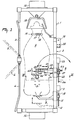
- FIG. 1 shows a milking parlour in which, inside a railing consisting of the front railing portion 1, the rear railing portion 2 and the railing doors 3 and 4, an animal, in the present case a cow A, is present.
- the milking parlour includes a milking robot 5, by means of which the teat cups 6 can be connected to the schematically shown teats 7 of the udder of the cow A.
- the milking robot co-operates with a contacting member 8.
- the contacting member 8 can be moved with the aid of a stepper motor 9, a threaded spindle 10 connected thereto and a straight guide member 11 to over a horizontal carrier 12 which forms part of the rear railing portion 2.
- the milking parlour comprises a computer system 13 which controls an automatic feeder.
- the computer system 13 of the automatic feeder operates independently of a computer system 14 for the milking robot and, each time it detects, identifies and moreover accepts an animal A in the milking parlour, it can deposit a quantity of fodder matched to the animal in a feed trough 15 attached to the front railing portion 1.
- the animal is provided with a collar 16, to which two separate indication and information members 17 and 18 are attached. These members each separately supply control signals to the two computer systems 13, 14 and contribute to an independent action of both computers.
- the milking parlour is further provided with an indicator device 19 for measuring the milk flow coming from a teat 7 of the udder of the animal A. For each of the teats a warning light 20 is present, which lights up when it is determined via a sensor in a teat cup 6 or in the milk line 21 of a cup 6 that the milk flow has stopped or decreased to below a predetermined value.
- the indicator device 19 may alternatively be designed such that it has two warning lights for the milk flow from each teat 7, one warning light emitting green light during milking and the other one emitting red light when the milk flow from a related teat has decreased to below the preset threshold value.
- the indicator is an acoustic device in the form of a buzzer.
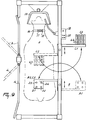
- the milking robot 5 is slidably disposed on a horizontal carrier 12 which forms part of the rear railing portion 2.
- the milking robot 5 comprises a straight guide member 22, a stepper motor 23 driving a threaded spindle 24, which engages the straight guide member 22.
- the stepper motor 23 is controlled by the computer 14 of the milking robot.
- Figure 2 shows at the bottom side of the straight guide member 22 a holder 26 which is arranged pivotably about a vertical shaft 27 connected to the straight guide member 22.
- a carrier member 33 for the teat cups 6 is disposed at a square angle on the end of the slidable arm portion 31.
- the teat cups 6 are, seen in plan view, arranged in a V-form on the carrier member 33.
- the carrier member 33 includes a chamber portion 34 and a contacting member portion 35, which in this construction are one integral whole.
- the slidable arm portion and the teat cups attached thereto can be moved relative to the rigid arm portion 30 with the aid of a threaded spindle 48 which meshes with a threaded element 49 at the bottom side of the carrier member 33.
- the threaded spindle 48 is driven by a stepper motor 50, which is controlled by the computer system 14 of the milking robot 5.
- the arm 29 is supported and activated pivotably by means of an adjusting cylinder 37.
- the piston rod thereof acts near the midway point of the rigid arm portion 30 on a horizontal shaft 38 connected between two lugs to the rigid arm portion.
- the adjusting cylinder 37 is located in the extension of the arm 29 and, in this situation, extends under the end of the vertical shaft 27 to a holder arm 40 of the holder 26.
- the cylinder portion of the adjusting cylinder 37 is supported relative to the holder arm 40 via a rod 41 which is provided in the extension of the cylinder and is passed through a bore in a block 42, which block 42 is connected pivotably to the holder arm 40 via horizontal stub axles 43.
- the end of the sliding rod 41 which is provided with thread, is fitted with an adjusting nut 44.
- a pressure spring 45 Disposed between the cylinder portion of the adjusting cylinder 37 and the block 42 is a pressure spring 45, and a second pressure spring 46 is disposed between the adjusting nut 44 and the block 42.
- Figures 3 and 4 show a laser device 52 on the carrier member 33.
- the computer of the milking robot 5 determines the position of the carrier member 33, and consequently the position of the teat cups 6, with the aid of a laser device 52 which is disposed on the carrier member 33, projects to over the teat cups and supplies the computer 14 with signals on the basis of reflected radiation, so that the position of the teats 7 with respect to the carrier member 33 can be determined.
- the laser device 52 is positioned, seen with respect to the udder of the animal A near the teat cups arranged at the head end of the animal, on an imaginary perpendicular centre line, directed transversely to the arm 29, between the four teat cups.
- the leading teat cups 6 are spaced apart from each other by a smaller distance than the trailing pair of teat cups, so that each centre of a teat cup 6 indicates a point for the lines of an imaginary arrow tip which, in a plan view, is directed towards the udder.
- cylinders 51 which are pneumatically or hydraulically operable via supply lines 47.
- a flexible member 53, 53A Connected to the piston rod 55 of each of the cylinders 51 is a flexible member 53, 53A, which is connected to a teat cup 6.
- the piston rod 55 of a cylinder 51 is retracted that far that a teat cup 6 is pulled up against a plane of contact 54 on the contacting portion 35 of the carrier member 33.
- FIGS 5, 6 and 8 show the configuration of the teat cups 6 during milking.
- the flexible member 53, 53A is not tightened, so that the milked animal A can move free from and to the robot arm 30.
- a plane of contact 54 has a curvature which at least substantially corresponds to the circumferential curvature of a teat cup 6.
- a plane of contact 54 is provided on the carrier member 33, which is in the form of an approximately square tube 34.
- the flexible member 53, 53A is preferably disposed between upright walls of the tube, so that, when it is tightened, a stable contact of the cup 6 with the contacting portion 35 is obtained in all circumstances.
- the plane of contact 54 is constituted by a wall 58 which closes the tube 34 and in which one or a plurality of apertures 60 for the flexible member 53, 53A are made.
- the apertures 60 are of a conical shape, so that the flexible member 53, 53A can smoothly be pulled through the apertures 60 at different angles.
- a flexible member 53, 53A is connected to a piston rod 55 via an intermediate member 59.
- the intermediate member may have the shape of an isosceles triangle, the intermediate member 59 being connected to the piston rod 55 near the apex angle of the said triangular shape.
- a flexible member can consist of two cables or cords 53 of a suitable flexible material, which cables 53 have one end connected in a lateral direction, i.e. to an upright wall of a teat cup 6. The other end may be attached to the intermediate member 59.
- the flexible member consists of a strip or belt 53A which extends in an upwardly directed plane.
- Figure 7 shows, in a cross-sectional view, at the bottom side of the bottom wall 57 of the carrier member 33 a flattened tube 39, through which for the purpose of protection the milk hoses 21 of the teat cups 6 are passed.
- a tube 39 through which also further lines may be passed, prevents the robot arm 29 from being caught on obstacles, if any, by means of its lines and wires.
- the teat cups 6 can be held against or onto the carrier member 33 by means of the cylinders 51, they can also be held against or onto the carrier member 33 by means of on/off switchable electromagnets.
- These electromagnets are mounted on the carrier member, e.g. near the planes of contact 54, and are individually operable. Particularly, they can be switched on together, while they can be switched off individually.
- the electromagnets work together with the cylinders 51.
- the cylinders 51 are able to pull up the teat cups 6 against or onto the carrier member 33 by means of one or more cables 53 or by means of the belt 53A, while the electromagnets are able to hold the teat cups against or onto the carrier member 33.
- control signals can be generated which cause an off-switching of the electromagnet for a relevant teat cup 6 when said teat cup is to be attached to a teat, and an on-switching of said electromagnet when this teat cup has to be uncoupled from the relevant teat and be reconnected to the carrier member 33.
- the control signals can also provoke an activating of the cylinder 51 of this teat cup 6 for a predetermined time interval as soon as the teat cup 6 has to be uncoupled from said teat.
- said teat cup is moved upwardly and sucked around a respective teat by means of a partial vacuum generated in said teat cup 6.
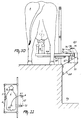
- Figure 9 shows a milking parlour in which a cow A is present, the milking implement comprising apart from the milk robot 5 a teat-cleaning device 63 with cleaning elements 64 for cleaning the teats of the animal to be milked.
- the milk robot 5 and the cleaning device 63 are displaceably mounted on a guide member arranged at one of the longitudinal sides of the milk box or milking parlour, while the carrier member 33 as well as the cleaning elements 64 are rotatable about an upwardly directed axis from a position outside the milk box into a position under the animal.
- the direction of rotation of the carrier member from the rest position is opposite to the direction of rotation of the cleaning elements 64 from the rest position.
- the carrier member 33 and cleaning elements 64 are able to follow circle-like curves to move through a foremost and a hindmost leg, the first part of which curves being directed opposite to each other.
- the robot does not only milk the cow A, but first cleans her teats 7.
- the teat cups 6 are in position B1 and the teat-cleaning device 63 is in position C1.
- the teat cleaner 63 rotates through 180° to the position C2. Thereafter the cleaning device 63 moves along the horizontal carrier 12 to position C3.
- the cleaning device 63 is at a somewhat lower level than the horizontal carrier 12, so that it can pass under it in an advantageous manner.
- the teats are cleaned in the position C3. Thereafter the cleaning device moves again to the position C2 and the teat cups automatically move from position B1 to position B2, the latter position corresponding to the position C3 of the cleaning device 63.
- the laser detector 52 or a different type of detector, determines the position of the teats 7, whereafter the teat cups are automatically coupled thereto.
- the teat cups 6 return to position B1 and, after a further cow A has arrived in the milking parlour, the teat cleaning device 63 moves again to position C3 and the procedure described is repeated.
- FIG 10 is a rear view and Figure 11 a reduced plan view of the milking parlour, in which a manually operated milking machine 65 is provided against the wall of an operator's pit 73.
- the teat cups 6, as was also the case with the milking robot 5 already described, are disposed on an approximately horizontally extending arm 66 which is movable in all directions.
- the arm 66 is upwardly pivotal about a shaft and is flexibly attached to a holder 68 by means of a pusher spring 67 bearing thereon. Because of this support, the teat cups 6 are easily couplable to the teats 7.
- the underpressure in the relevant teat cup 6 will be automatically stopped. This promotes a low somatic cell count of the milk and the risk of mastitis is reduced.
- the pneumatic cylinders 69 which uncouple the teat cups 6 from the teats 7 when the milk flow stops or decreases to below a predetermined preset value, are provided under the horizontal carrier arm 66.
- the height of the arm 66 carrying the cups 6 is adjustable by means of a locking member 70 which comprises a pressure member 74 and is also pivotal about the shaft 72.
- the arm 66 is further mounted such that it is rotatable about a vertical shaft 71. As is shown in Figure 11, the arm can be moved from a rest position E1 to an operative position E2, which corresponds to C2 and C3 in Figure 9.
- the locking member 70 has a serrated edge 73 which is rigid but can pivot together with the arm 66 about the upwardly extending shaft 71, into which edge a pawl 76 is drawn and locked there by a (non-shown) tension spring.
- the arm 66 with teat cups 6 is simultaneously locked thereby at the proper height. So as to be able to connect the cups 6 to the teats 7, the arm 66 can be pivoted about the vertical shaft 71 to under the udder in the position E2. Thereafter, if desired, the height can be adapted in a simple manner by lifting the pawl 76, whereafter the pusher spring 67 pushes the arm 66 and the cups 6 upwards. Lowering the arm 66 only requires a light manual pressing of the arm 66.
- the teat cups 6, as shown have been connected during milking in an upwardly directed position to the carrier arm 66, it is not absolutely necessary to uncouple the teat cups 6 from the teat, when the milk flow stops. Without the presence of underpressure in the teat cup, the teat cup 6, while resting on a preferably dish-like seat in a plateau at the end of the arm 66, might remain connected to or near the teat until all four teat cups 6 have ended their milking action.
- the carrier member has four teat cups 6 which are connected to a carrier member 33 via flexible members 53, 53A. Taken in a direction from the rear, from left to right the teats might be numbered as follows: rear left D1, rear right D2, front left D3 and front right D4.
- the teat cup for teat D1 is, for example, connected first. As soon as the cup 6 has been connected to the teat 7 and the milking operation has started, the air pressure in the pneumatic adjusting cylinder 51 of this teat cup 6 stops and the teat cup 6 then becomes freely movable relative to the carrier member 33. If an electromagnet has been used for the connection, the electric current is at that moment switched off from the electromagnet. Thereafter the carrier member 33 automatically moves to teat D2, where the same action occurs. This coupling method is repeated also for the teats D3 and D4.
- the teat cups 6 are flexibly connected to the robot arm 29 by means of the milk hoses 21 and the flexible members 53, 53A.
- This flexible connection is advantageous for the milk yield.
- the flexibility of the teat cup 6 connected to the teat 7 is still further increased if the robot arm 29 is moved by one or more hydraulic or pneumatic cylinders and if the pressure on the oil or of the air in the cylinders, which determine the location of the robot arm, is removed.
- the connected teat cups 6 can also move in all directions in this manner.
- the underpressure in the teat cup 6 automatically disappears and simultaneously or substantially simultaneously the flexible members 53, 53A pull the teat cup 6 into its seat, i.e. its plane of contact 54, at the carrier member 33.
- This rapid drop of the underpressure in the teat cup 6 and the withdrawal of the teat cup are beneficial to a low somatic cell count of the milk.
- the risk of illnesses, such as mastitis, is reduced thereby and milking is more agreeable to the animal.
- the robot arm rotates through approximately 180° to a position outside the milking station and the cow can leave the milking parlour.
- a computer 13 which controls the feeding system and makes any further information available, is disposed near the feed trough.
- This computer 13 can, for example, control the quantity of fodder served to the cow in the feed trough.
- the cow has a collar 16 which forms part of cow-identification means.
- Two indication-information members 17, 18 are attached to the collar 16 of the cow A.
- the one information member co-operates with the computer-controlled feeding system.
- the other information member co-operates with the computer 14, which is provided near the rear side of the cow A and manages the process control of the milking robot 5.
- the cow-identification means are provided with a first microprocessor unit in which the relevant data for the fodder supply of an animal to be milked is stored, a second microprocessor unit in which the relevant data for the milking process of an animal to be milked is stored and with a transceiver system.
- the indication-information member 17 includes the first microprocessor unit with the transceiver system and is able to communicate with the transceiver system of the computer system for feeding the animal.
- the indication-information member 18 includes the second microprocessor with the first mentioned transceiver system and is able to communicate with the transceiver system of the computer system for controlling the milking robot 5 and the automatic milking.
- the pressure springs 45, 46 provided in the robot arm produce a flexible up and down motion, whereby the weight of a teat cup 6 and carrier member 33 is reduced.
- the up and down motion of the teat cup 6 can, as shown, be effected pneumatically.
- a stepper motor can adjust the length of the telescopic robot arm 29.
- the stepper motor structures can be replaced by hydraulic or pneumatic cylinders or suchlike structures.
- a teat cup 6, mounted at the end of the robot arm can be moved upwardly, downwardly and laterally and at the same time in all directions, after activation of the relevant stepper motor and/or adjusting cylinder.
- the milking implement can still function adequately if two teats of the cow are adjacent to each other spaced apart by only a few centimetres, e.g. 2 cms, as, for example, the rearmost teat cups D1 and D2 are located in the initial position very closely to each other on their carrier member 33. This arrangement is important for a milking robot 5 which must always operate, also during the night, without any supervision.
- the milking implement comprised of a number of teat cups 6 which are connectable to a number of teats 7 of an animal, such as a cow A, is preferably used in a stable with freely moving cows or a similar such accommodation.
- the milking system comprising the said milking and cleaning implements and the computer 14, and the feeding system can then be of an automatic type and be designed such that the computers 13, 14 controlling the milking system and the feeding system allow a cow to enter the milking parlour, in accordance with the sequence in which she is recorded in the computer.
- the milking system and the feeding system can be automated and designed such that the computers 13, 14 controlling the milking system and the feeding system ensure that a cow which is at the beginning of a lactation period is given priority, as regards her entrance to the milking parlour, over cows which are at the end of the lactation period. Therefore, the implement is provided with register means for registering the lactation period of the animals. Particularly, these register means are forming part of the second microprocessor unit of the cow-identification means, in which microprocessor unit the further relevant data for the milking process of the animal to be milked is stored.
- the computer system for controlling the milking robot comprises a special programme to ensure that the animals which are at the beginning of a lactation period are given priority for entering the milking parlour over animals which are not at the beginning of the lactation period.
- the milking system and the feeding system may also be of such an automated construction and so designed that the computers 13, 14 controlling the milking system and the feeding system allow cows A into the milking parlour in accordance with serial numbers such as A1, A2, A3, A4, A5 etc., assigned to the cows A.
Claims (6)
- Dispositif pour la traite d'animaux, comprenant une stalle de traite avec un robot trayeur (5) et un système informatique (14) commandant ledit robot trayeur (5), le robot trayeur (5) étant muni de moyens pour relier automatiquement des godets de trayons (6) aux trayons d'un animal et pour traire l'animal automatiquement, le dispositif comprenant en outre des moyens pour identifier un animal, coopérant avec ledit système informatique (14) pour identifier les animaux,
caractérisé en ce que des moyens d'enregistrement sont prévus pour enregistrer la période de lactation de l'animal, et en ce que le système informatique (14) comprend en outre un programme pour assurer que les animaux qui sont au début d'une période de lactation reçoivent priorité pour entrer dans la stalle de traite, de préférence aux animaux qui ne sont pas au début de la période de lactation. - Dispositif selon la revendication 1, caractérisé en ce que les moyens d'enregistrement font partie de l'unité à microprocesseur des moyens d'identification des animaux, dans laquelle unité à microprocesseur les autres données pertinentes pour l'opération de traite de l'animal à traire sont mises en mémoire.
- Dispositif selon la revendication 1 ou 2, caractérisé en ce qu'en dehors de l'ordinateur (14) pour commander le robot trayeur et pour la traite automatique de l'animal, un autre système informatique (13) est prévu pour nourrir l'animal.
- Dispositif selon la revendication 3, caractérisé en ce qu'au moins un des deux systèmes informatiques (13, 14) est muni d'un système émetteur-récepteur pour communiquer avec un système émetteur-récepteur faisant partie des moyens pour identifier un animal.
- Dispositif selon la revendication 4, caractérisé ence que les moyens pour identifier un animal sont munis d'une première unité à microprocesseur dans laquelle les données pertinentes pour la fourniture de fourrage à un animal à traire, sont mises en mémoire, ladite première unité à microprocesseur étant capable de communiquer avec le système informatique pour le dispositif d'affourragement, et d'une deuxième unité à microprocesseur dans laquelle les données pertinentes pour l'opération de traite d'un animal à traire sont mises en mémoire, ladite deuxième unité à microprocesseur étant capable de communiquer avec l'autre système informatique pour commander le robot trayeur (5) et la traite automatique.
- Dispositif selon la revendication 4 ou 5, caractérisé en ce que le robot trayeur (5) est muni d'un système émetteur-récepteur pour communiquer avec un système émetteur-récepteur faisant partie d'un dispositif indicateur, par exemple un affichage ou un dispositif acoustique ou des lumières avertisseuses, situées dans la stalle de traite ou en dehors de celle-ci.
Applications Claiming Priority (2)
| Application Number | Priority Date | Filing Date | Title |
|---|---|---|---|
| NL9200091A NL9200091A (nl) | 1992-01-17 | 1992-01-17 | Melkmachine. |
| NL9200091 | 1992-01-17 |
Publications (2)
| Publication Number | Publication Date |
|---|---|
| EP0551957A1 EP0551957A1 (fr) | 1993-07-21 |
| EP0551957B1 true EP0551957B1 (fr) | 1996-12-11 |
Family
ID=19860316
Family Applications (7)
| Application Number | Title | Priority Date | Filing Date |
|---|---|---|---|
| EP93200104A Expired - Lifetime EP0551957B1 (fr) | 1992-01-17 | 1993-01-15 | Dispositif pour la traite d'animaux |
| EP93200105A Expired - Lifetime EP0551958B1 (fr) | 1992-01-17 | 1993-01-15 | Dispositif pour la traite d'animaux |
| EP93200108A Expired - Lifetime EP0551960B2 (fr) | 1992-01-17 | 1993-01-15 | Dispositif de traite automatique d'animaux |
| EP93200106A Expired - Lifetime EP0551959B2 (fr) | 1992-01-17 | 1993-01-15 | Dispositif de traite automatique d'un animal |
| EP93200103A Expired - Lifetime EP0551956B1 (fr) | 1992-01-17 | 1993-01-15 | Dispositif de traite automatique d'un animal |
| EP97201350A Revoked EP0792579B1 (fr) | 1992-01-17 | 1993-01-15 | Dispositif pour la traite d'animaux |
| EP93200107A Expired - Lifetime EP0555895B1 (fr) | 1992-01-17 | 1993-01-15 | Dispositif de traite d'animaux |
Family Applications After (6)
| Application Number | Title | Priority Date | Filing Date |
|---|---|---|---|
| EP93200105A Expired - Lifetime EP0551958B1 (fr) | 1992-01-17 | 1993-01-15 | Dispositif pour la traite d'animaux |
| EP93200108A Expired - Lifetime EP0551960B2 (fr) | 1992-01-17 | 1993-01-15 | Dispositif de traite automatique d'animaux |
| EP93200106A Expired - Lifetime EP0551959B2 (fr) | 1992-01-17 | 1993-01-15 | Dispositif de traite automatique d'un animal |
| EP93200103A Expired - Lifetime EP0551956B1 (fr) | 1992-01-17 | 1993-01-15 | Dispositif de traite automatique d'un animal |
| EP97201350A Revoked EP0792579B1 (fr) | 1992-01-17 | 1993-01-15 | Dispositif pour la traite d'animaux |
| EP93200107A Expired - Lifetime EP0555895B1 (fr) | 1992-01-17 | 1993-01-15 | Dispositif de traite d'animaux |
Country Status (6)
| Country | Link |
|---|---|
| EP (7) | EP0551957B1 (fr) |
| AT (2) | ATE164485T1 (fr) |
| DE (5) | DE69306421T2 (fr) |
| DK (2) | DK0551959T4 (fr) |
| FR (1) | FR2690809B1 (fr) |
| NL (1) | NL9200091A (fr) |
Families Citing this family (52)
| Publication number | Priority date | Publication date | Assignee | Title |
|---|---|---|---|---|
| NL9300443A (nl) * | 1993-03-11 | 1994-10-03 | Prolion Bv | Werkwijze en inrichting voor het bewaken van dierfuncties. |
| NL9301377A (nl) * | 1993-08-09 | 1995-03-01 | Lely Nv C Van Der | Inrichting voor het automatisch melken van dieren. |
| NL9301414A (nl) * | 1993-08-16 | 1995-03-16 | Lely Nv C Van Der | Inrichting voor het automatisch melken van dieren. |
| NL9301643A (nl) * | 1993-09-23 | 1995-04-18 | Lely Nv C Van Der | Inrichting voor het automatisch melken van dieren. |
| NL9302154A (nl) * | 1993-12-10 | 1995-07-03 | Nedap Nv | Informatiesysteem voor de melkveehouderij. |
| NL9400054A (nl) * | 1994-01-13 | 1995-08-01 | Maasland Nv | Inrichting voor het automatisch melken van dieren. |
| NL9400471A (nl) * | 1994-03-25 | 1995-11-01 | Maasland Nv | Constructie met een inrichting voor het melken van dieren. |
| DK1131997T3 (da) * | 1994-03-25 | 2006-11-13 | Maasland Nv | Konstruktion, herunder et redskab til malkning af dyr |
| NL9400472A (nl) * | 1994-03-25 | 1995-11-01 | Maasland Nv | Constructie met een inrichting voor het melken van dieren. |
| NL9400495A (nl) * | 1994-03-29 | 1995-11-01 | Maasland Nv | Werkwijze en inrichting voor het automatisch melken van dieren. |
| NL9500362A (nl) * | 1994-04-14 | 1995-11-01 | Maasland Nv | Werkwijze voor het automatisch melken van dieren en inrichting waarin deze werkwijze kan worden toegepast. |
| NL9401937A (nl) * | 1994-04-27 | 1995-12-01 | Maasland Nv | Werkwijze voor het automatisch melken van dieren en inrichting waarin deze werkwijze kan worden toegepast. |
| AU724419B2 (en) * | 1994-04-27 | 2000-09-21 | Maasland N.V. | A method of automatically milking animals and an implement for applying same |
| NL9400992A (nl) * | 1994-06-17 | 1996-02-01 | Maasland Nv | Inrichting voor het automatisch melken van dieren. |
| NL9401033A (nl) * | 1994-06-23 | 1996-02-01 | Maasland Nv | Constructie met een inrichting voor het automatisch melken van dieren. |
| NL9401113A (nl) * | 1994-07-04 | 1996-02-01 | Maasland Nv | Constructie met een inrichting voor het automatisch melken van dieren. |
| NL9401114A (nl) * | 1994-07-04 | 1996-02-01 | Maasland Nv | Constructie met een inrichting voor het automatisch melken van dieren. |
| US6062164A (en) * | 1994-07-28 | 2000-05-16 | Prolion B.V. | Device and method for automatically milking animals |
| NL9401238A (nl) * | 1994-07-28 | 1996-03-01 | Prolion Bv | Inrichting voor het automatisch melken van dieren. |
| US5743209A (en) * | 1994-08-01 | 1998-04-28 | La Federation Francaise De Controle Laitier (F.F.C.L.) | System and method for monitoring and controlling milk production at dairy farms |
| NL9401374A (nl) * | 1994-08-25 | 1996-04-01 | Maasland Nv | Inrichting voor het automatisch melken van dieren. |
| SE9503588D0 (sv) * | 1995-10-13 | 1995-10-13 | Tetra Laval Holdings & Finance | A method of milking and a milking apparatus |
| NL1001646C2 (nl) * | 1995-11-14 | 1997-05-21 | Maasland Nv | Constructie met een inrichting voor het melken van dieren. |
| NL1001645C2 (nl) † | 1995-11-14 | 1997-05-21 | Maasland Nv | Constructie met een inrichting voor het melken van dieren. |
| DE19728415A1 (de) * | 1997-07-03 | 1999-01-07 | Volker Boekhoff | Verfahren und Vorrichtung zur automatisierten landwirtschaftlichen Tierhaltung |
| NL1006586C2 (nl) * | 1997-07-15 | 1999-01-18 | Maasland Nv | Constructie met een inrichting voor het melken van dieren, alsmede een werkwijze daarvoor. |
| SE514007C2 (sv) | 1998-09-04 | 2000-12-11 | Alfa Laval Agri Ab | Skyddsorgan vid anordning för djurskötsel |
| NL1010323C2 (nl) * | 1998-10-15 | 2000-04-18 | Maasland Nv | Werkwijze voor het automatisch melken van dieren en volautomatische melkmachine met een melkrobot geschikt voor het uitvoeren van de werkwijze. |
| DE19901241A1 (de) | 1999-01-14 | 2000-07-20 | Westfalia Landtechnik Gmbh | Vorrichtung zum Ansetzen wenigstens eines Melkbechers an eine Zitze eines Tieres |
| SE514439C2 (sv) * | 1999-05-28 | 2001-02-26 | Delaval Holding Ab | Kopplingsanordning för en spenkopp |
| SE0000965D0 (sv) | 2000-03-21 | 2000-03-21 | Alfa Laval Agri Ab | A device for supporting a milking member |
| SE517141C2 (sv) | 2000-06-07 | 2002-04-23 | Delaval Holding Ab | Förfarande för mjölkning där djuren rankas samt mjölkningsstall och datorprogramvara härför |
| NL1015670C2 (nl) * | 2000-07-10 | 2002-01-11 | Lely Entpr Ag | Inrichting voor het automatisch melken van dieren. |
| NL1017984C2 (nl) * | 2001-05-02 | 2002-11-05 | Idento Electronics Bv | Melkinrichting. |
| NL1019061C2 (nl) * | 2001-09-28 | 2003-04-02 | Lely Entpr Ag | Werkwijze voor het verzamelen van meetgegevens tijdens het automatisch melken van een dier. |
| SE522258C2 (sv) † | 2002-04-09 | 2004-01-27 | Delaval Holding Ab | Förfarande och arrangemang vid mjölkningsordning |
| NL1020805C2 (nl) * | 2002-06-06 | 2003-12-09 | Lely Entpr Ag | Werkwijze en inrichting voor het verrichten van metingen aan melk verkregen van het dier. |
| NL1020784C2 (nl) * | 2002-06-06 | 2003-12-09 | Lely Entpr Ag | Inrichting voor het automatisch melken van een dier. |
| SE527083C2 (sv) * | 2004-03-25 | 2005-12-20 | Delaval Holding Ab | Förfarande och mjölkningsstation för mjölkdjur |
| SE527496C2 (sv) * | 2004-06-22 | 2006-03-21 | Delaval Holding Ab | Gripanordning, robotarm och mjölkningsrobot |
| SE0500043D0 (sv) | 2005-01-10 | 2005-01-10 | Delaval Holding Ab | A milking arrangement |
| SE529127C2 (sv) | 2005-09-02 | 2007-05-08 | Delaval Holding Ab | Detekteringsarrangemang jämte -metod för en magnetisk gripanordning |
| EP1913811B1 (fr) * | 2006-10-18 | 2014-02-26 | DeLaval Holding AB | Nettoyage dans un système de traite |
| GB0703917D0 (en) | 2007-02-28 | 2007-04-11 | Iti Scotland Ltd | A Collar for an animal |
| WO2010028912A2 (fr) * | 2008-09-10 | 2010-03-18 | Delaval Holding Ab | Dispositif de préhension, bras robotique, robot de traite et procédé |
| US9968069B2 (en) | 2011-03-18 | 2018-05-15 | Gea Farm Technologies Gmbh | Milking cluster and milking parlor having such a milking cluster |
| DE102011001404A1 (de) * | 2011-03-18 | 2012-09-20 | Gea Farm Technologies Gmbh | Melkzeug und Melkstand mit einem solchen Melkzeug |
| DE102012110501A1 (de) | 2012-03-14 | 2013-09-19 | Gea Farm Technologies Gmbh | Platzteiler einer Melkstandanordnung und Melkstandanordnung |
| DE102012102133A1 (de) | 2012-03-14 | 2013-09-19 | Gea Farm Technologies Gmbh | Melkstandanordnung mit einer innenrobotervorrichtung |
| US9545078B1 (en) | 2012-06-07 | 2017-01-17 | Lely Patent N.V. | Electro-hydraulical actuator for a robot arm |
| DE102014107124A1 (de) | 2014-05-20 | 2015-11-26 | Gea Farm Technologies Gmbh | Armeinrichtung für eine Melkstandanordnung zum automatischen Melken von milchgebenden Tieren, Platzteiler einer Melkstandanordnung und Melkstandanordnung |
| WO2019221659A1 (fr) * | 2018-05-18 | 2019-11-21 | Delaval Holding Ab | Commande d'une station de traite |
Family Cites Families (25)
| Publication number | Priority date | Publication date | Assignee | Title |
|---|---|---|---|---|
| US2613636A (en) * | 1950-06-30 | 1952-10-14 | Babson Bros Co | Support for milking apparatus |
| NL6702077A (fr) * | 1967-02-07 | 1968-08-12 | ||
| US3726252A (en) * | 1971-01-11 | 1973-04-10 | Babson Bros Co | Automatic milker |
| FR2183609B1 (fr) * | 1972-05-12 | 1977-07-22 | Gol Sp | |
| AU464891B2 (en) * | 1972-09-18 | 1975-09-11 | Babson Bros. Co | Automatic milker |
| US4010714A (en) * | 1974-03-08 | 1977-03-08 | Director, National Institute Of Animal Industry | System for managing milking-cows in stanchion stool |
| US4408564A (en) * | 1979-07-23 | 1983-10-11 | Flocchini Andrew J | Milking apparatus |
| US4463353A (en) * | 1981-08-17 | 1984-07-31 | Ralston Purina Company | Animal feeding and monitoring system |
| SE430559B (sv) † | 1982-04-08 | 1983-11-28 | Alfa Laval Ab | Sett att mjolka och anordning herfor |
| US4516530A (en) * | 1983-10-14 | 1985-05-14 | Germania Dairy Automation, Inc. | Milk sweep method and apparatus for automated milking systems |
| NZ210240A (en) * | 1984-11-19 | 1989-04-26 | Allflex Int | Milk flow measure and teat cup removal |
| EP0332231B2 (fr) * | 1985-01-16 | 2002-06-12 | Maasland N.V. | Dispositif de traite d'animaux, par exemple de vaches |
| ATE120928T1 (de) * | 1985-01-16 | 1995-04-15 | Lely Nv C Van Der | Gerät zum melken von tieren, z.b. kühen. |
| CA1272156A (fr) * | 1985-11-01 | 1990-07-31 | Maltec, Llc | Detecteur optique d'un courant de lait et dispositif de coupure a depression pour trayeuse mecanique |
| NL8602942A (nl) * | 1986-11-19 | 1988-06-16 | Multinorm Bv | Verplaatsbare ruimte waarin een inrichting voor het automatisch melken van een beest is opgesteld. |
| DE3702465A1 (de) * | 1987-01-28 | 1988-08-11 | Duevelsdorf & Sohn Gmbh & Co K | Verfahren und vorrichtung zum melken und ggfs. fuettern von freilaufenden, identifizierungsmittel tragenden kuehen |
| NL193715C (nl) * | 1987-07-23 | 2000-08-04 | Lely Nv C Van Der | Inrichting voor het melken van een dier. |
| DE3775773D1 (de) * | 1987-09-08 | 1992-02-13 | Cemagref | Automatische melkmaschine. |
| NL8702285A (nl) * | 1987-09-24 | 1989-04-17 | Gascoigne Melotte Bv | Melkinrichting. |
| US4941433A (en) † | 1988-05-23 | 1990-07-17 | Agri-Automation Company, Ltd. | Milking method and related apparatus |
| NL8802332A (nl) * | 1988-09-21 | 1990-04-17 | Lely Nv C Van Der | Inrichting voor het melken van een dier. |
| GB8900084D0 (en) * | 1989-01-04 | 1989-03-01 | British Res Agricult Eng | Milking |
| NL193553C (nl) * | 1989-02-27 | 2003-01-10 | Lely Entpr Ag | Melkinstallatie. |
| NL9002047A (nl) * | 1990-09-18 | 1992-04-16 | Lely Nv C Van Der | Reinigingsinstallatie. |
| GB9113405D0 (en) † | 1991-06-20 | 1991-08-07 | Silsoe Research Inst | Automatic milking |
-
1992
- 1992-01-17 NL NL9200091A patent/NL9200091A/nl not_active Application Discontinuation
-
1993
- 1993-01-13 FR FR9300272A patent/FR2690809B1/fr not_active Expired - Fee Related
- 1993-01-15 DE DE69306421T patent/DE69306421T2/de not_active Expired - Lifetime
- 1993-01-15 EP EP93200104A patent/EP0551957B1/fr not_active Expired - Lifetime
- 1993-01-15 EP EP93200105A patent/EP0551958B1/fr not_active Expired - Lifetime
- 1993-01-15 EP EP93200108A patent/EP0551960B2/fr not_active Expired - Lifetime
- 1993-01-15 DE DE69319155T patent/DE69319155T3/de not_active Expired - Lifetime
- 1993-01-15 EP EP93200106A patent/EP0551959B2/fr not_active Expired - Lifetime
- 1993-01-15 DE DE69312333T patent/DE69312333T2/de not_active Expired - Lifetime
- 1993-01-15 EP EP93200103A patent/EP0551956B1/fr not_active Expired - Lifetime
- 1993-01-15 EP EP97201350A patent/EP0792579B1/fr not_active Revoked
- 1993-01-15 AT AT93200106T patent/ATE164485T1/de not_active IP Right Cessation
- 1993-01-15 DK DK93200106T patent/DK0551959T4/da active
- 1993-01-15 EP EP93200107A patent/EP0555895B1/fr not_active Expired - Lifetime
- 1993-01-15 DK DK97201350T patent/DK0792579T3/da active
- 1993-01-15 AT AT97201350T patent/ATE203872T1/de not_active IP Right Cessation
- 1993-01-15 DE DE69328941T patent/DE69328941T2/de not_active Expired - Lifetime
- 1993-01-15 DE DE4300884A patent/DE4300884A1/de not_active Withdrawn
Non-Patent Citations (1)
| Title |
|---|
| Handboek voor de Rundveehouderij, 1993, Informatie en Kenniscentrum Veehouderij, Lelystad (NL), p. 249. * |
Also Published As
| Publication number | Publication date |
|---|---|
| EP0555895B1 (fr) | 2000-07-05 |
| EP0792579A2 (fr) | 1997-09-03 |
| EP0551959B2 (fr) | 2001-06-20 |
| DK0551959T3 (da) | 1999-01-11 |
| DE69319155T2 (de) | 1999-02-11 |
| EP0551956B1 (fr) | 1996-12-11 |
| NL9200091A (nl) | 1993-08-16 |
| DE69319155T3 (de) | 2007-03-29 |
| EP0551956A1 (fr) | 1993-07-21 |
| EP0551960B2 (fr) | 2006-09-06 |
| ATE164485T1 (de) | 1998-04-15 |
| EP0551957A1 (fr) | 1993-07-21 |
| DK0551959T4 (da) | 2001-08-27 |
| EP0551959B1 (fr) | 1998-04-01 |
| EP0551958B1 (fr) | 1997-07-23 |
| DE69312333D1 (de) | 1997-09-04 |
| EP0551960A1 (fr) | 1993-07-21 |
| FR2690809B1 (fr) | 1995-02-03 |
| DE69306421T2 (de) | 1997-06-26 |
| ATE203872T1 (de) | 2001-08-15 |
| EP0551960B1 (fr) | 1998-06-17 |
| EP0551959A1 (fr) | 1993-07-21 |
| DE69312333T2 (de) | 1998-02-26 |
| DE69306421D1 (de) | 1997-01-23 |
| EP0555895A1 (fr) | 1993-08-18 |
| EP0551958A1 (fr) | 1993-07-21 |
| EP0792579A3 (fr) | 1997-11-05 |
| DK0792579T3 (da) | 2001-11-12 |
| DE69319155D1 (de) | 1998-07-23 |
| DE4300884A1 (fr) | 1993-07-22 |
| DE69328941T2 (de) | 2001-02-01 |
| EP0792579B1 (fr) | 2001-08-08 |
| DE69328941D1 (de) | 2000-08-10 |
| FR2690809A1 (fr) | 1993-11-12 |
Similar Documents
| Publication | Publication Date | Title |
|---|---|---|
| EP0551957B1 (fr) | Dispositif pour la traite d'animaux | |
| EP0728412B1 (fr) | Dispositif de traite d'animaux | |
| EP0565189B1 (fr) | Structure de traite automatique d'animaux | |
| EP0716566B1 (fr) | Construction comprenant un dispositif de traite d'animaux automatique | |
| US6148766A (en) | Construction including an implement for automatically milking animals | |
| EP1131997A2 (fr) | Construction à dispositif pour la traite d'animaux | |
| AU684502B2 (en) | A construction for automatically milking animals | |
| EP0716567B1 (fr) | Construction comprenant un dispositif de traite automatique | |
| EP1208742A2 (fr) | Dispositif de traite automatique d'animaux | |
| EP0728411B1 (fr) | Dispositif de traite d'animaux | |
| NL9200095A (nl) | Melkmachine. | |
| NL9200097A (nl) | Melkmachine. | |
| NL9200098A (nl) | Melkmachine. | |
| NL9200092A (nl) | Melkmachine. | |
| EP0673596A1 (fr) | Construction avec dispositif pour la traite d'animaux | |
| NL9200099A (nl) | Melkmachine. | |
| NL9200096A (nl) | Melkmachine. | |
| NL9200093A (nl) | Melkmachine. | |
| NL9200094A (nl) | Melkmachine. |
Legal Events
| Date | Code | Title | Description |
|---|---|---|---|
| PUAI | Public reference made under article 153(3) epc to a published international application that has entered the european phase |
Free format text: ORIGINAL CODE: 0009012 |
|
| AK | Designated contracting states |
Kind code of ref document: A1 Designated state(s): DE FR GB NL |
|
| 17P | Request for examination filed |
Effective date: 19940110 |
|
| 17Q | First examination report despatched |
Effective date: 19950817 |
|
| GRAG | Despatch of communication of intention to grant |
Free format text: ORIGINAL CODE: EPIDOS AGRA |
|
| GRAH | Despatch of communication of intention to grant a patent |
Free format text: ORIGINAL CODE: EPIDOS IGRA |
|
| GRAH | Despatch of communication of intention to grant a patent |
Free format text: ORIGINAL CODE: EPIDOS IGRA |
|
| GRAA | (expected) grant |
Free format text: ORIGINAL CODE: 0009210 |
|
| AK | Designated contracting states |
Kind code of ref document: B1 Designated state(s): DE FR GB NL |
|
| REF | Corresponds to: |
Ref document number: 69306421 Country of ref document: DE Date of ref document: 19970123 |
|
| ET | Fr: translation filed | ||
| PLBE | No opposition filed within time limit |
Free format text: ORIGINAL CODE: 0009261 |
|
| STAA | Information on the status of an ep patent application or granted ep patent |
Free format text: STATUS: NO OPPOSITION FILED WITHIN TIME LIMIT |
|
| 26N | No opposition filed | ||
| REG | Reference to a national code |
Ref country code: GB Ref legal event code: IF02 |
|
| PGFP | Annual fee paid to national office [announced via postgrant information from national office to epo] |
Ref country code: GB Payment date: 20030108 Year of fee payment: 11 |
|
| PG25 | Lapsed in a contracting state [announced via postgrant information from national office to epo] |
Ref country code: GB Free format text: LAPSE BECAUSE OF NON-PAYMENT OF DUE FEES Effective date: 20040115 |
|
| GBPC | Gb: european patent ceased through non-payment of renewal fee |
Effective date: 20040115 |
|
| NLS | Nl: assignments of ep-patents |
Owner name: LELY PATENT N.V. Effective date: 20080109 |
|
| REG | Reference to a national code |
Ref country code: FR Ref legal event code: TP |
|
| PGFP | Annual fee paid to national office [announced via postgrant information from national office to epo] |
Ref country code: NL Payment date: 20110128 Year of fee payment: 19 Ref country code: FR Payment date: 20110301 Year of fee payment: 19 |
|
| PGFP | Annual fee paid to national office [announced via postgrant information from national office to epo] |
Ref country code: DE Payment date: 20120427 Year of fee payment: 20 |
|
| REG | Reference to a national code |
Ref country code: NL Ref legal event code: V1 Effective date: 20120801 |
|
| REG | Reference to a national code |
Ref country code: FR Ref legal event code: ST Effective date: 20120928 |
|
| PG25 | Lapsed in a contracting state [announced via postgrant information from national office to epo] |
Ref country code: FR Free format text: LAPSE BECAUSE OF NON-PAYMENT OF DUE FEES Effective date: 20120131 |
|
| REG | Reference to a national code |
Ref country code: DE Ref legal event code: R071 Ref document number: 69306421 Country of ref document: DE |
|
| PG25 | Lapsed in a contracting state [announced via postgrant information from national office to epo] |
Ref country code: NL Free format text: LAPSE BECAUSE OF NON-PAYMENT OF DUE FEES Effective date: 20120801 |
|
| PG25 | Lapsed in a contracting state [announced via postgrant information from national office to epo] |
Ref country code: DE Free format text: LAPSE BECAUSE OF EXPIRATION OF PROTECTION Effective date: 20130116 |