EP0551455B1 - Women's shaver - Google Patents
Women's shaver Download PDFInfo
- Publication number
- EP0551455B1 EP0551455B1 EP92912202A EP92912202A EP0551455B1 EP 0551455 B1 EP0551455 B1 EP 0551455B1 EP 92912202 A EP92912202 A EP 92912202A EP 92912202 A EP92912202 A EP 92912202A EP 0551455 B1 EP0551455 B1 EP 0551455B1
- Authority
- EP
- European Patent Office
- Prior art keywords
- razor
- pair
- handle
- body member
- dispenser
- Prior art date
- Legal status (The legal status is an assumption and is not a legal conclusion. Google has not performed a legal analysis and makes no representation as to the accuracy of the status listed.)
- Expired - Lifetime
Links
- 241000237983 Trochidae Species 0.000 claims description 11
- 230000000717 retained effect Effects 0.000 claims description 3
- 230000002093 peripheral effect Effects 0.000 claims description 2
- 230000013011 mating Effects 0.000 abstract description 3
- 238000004806 packaging method and process Methods 0.000 abstract description 3
- 239000000463 material Substances 0.000 description 9
- 238000000034 method Methods 0.000 description 5
- 239000004033 plastic Substances 0.000 description 5
- 238000010276 construction Methods 0.000 description 4
- PPBRXRYQALVLMV-UHFFFAOYSA-N Styrene Chemical compound C=CC1=CC=CC=C1 PPBRXRYQALVLMV-UHFFFAOYSA-N 0.000 description 2
- 239000004677 Nylon Substances 0.000 description 1
- 230000000994 depressogenic effect Effects 0.000 description 1
- 238000007373 indentation Methods 0.000 description 1
- 238000004519 manufacturing process Methods 0.000 description 1
- 238000012986 modification Methods 0.000 description 1
- 230000004048 modification Effects 0.000 description 1
- 229920001778 nylon Polymers 0.000 description 1
- 230000000284 resting effect Effects 0.000 description 1
- 238000009736 wetting Methods 0.000 description 1
Images




Classifications
-
- B—PERFORMING OPERATIONS; TRANSPORTING
- B26—HAND CUTTING TOOLS; CUTTING; SEVERING
- B26B—HAND-HELD CUTTING TOOLS NOT OTHERWISE PROVIDED FOR
- B26B21/00—Razors of the open or knife type; Safety razors or other shaving implements of the planing type; Hair-trimming devices involving a razor-blade; Equipment therefor
- B26B21/40—Details or accessories
- B26B21/52—Handles, e.g. tiltable, flexible
- B26B21/521—Connection details, e.g. connection to razor heads
-
- B—PERFORMING OPERATIONS; TRANSPORTING
- B26—HAND CUTTING TOOLS; CUTTING; SEVERING
- B26B—HAND-HELD CUTTING TOOLS NOT OTHERWISE PROVIDED FOR
- B26B21/00—Razors of the open or knife type; Safety razors or other shaving implements of the planing type; Hair-trimming devices involving a razor-blade; Equipment therefor
- B26B21/08—Razors of the open or knife type; Safety razors or other shaving implements of the planing type; Hair-trimming devices involving a razor-blade; Equipment therefor involving changeable blades
- B26B21/14—Safety razors with one or more blades arranged transversely to the handle
- B26B21/22—Safety razors with one or more blades arranged transversely to the handle involving several blades to be used simultaneously
- B26B21/222—Safety razors with one or more blades arranged transversely to the handle involving several blades to be used simultaneously with the blades moulded into, or attached to, a changeable unit
- B26B21/225—Safety razors with one or more blades arranged transversely to the handle involving several blades to be used simultaneously with the blades moulded into, or attached to, a changeable unit the changeable unit being resiliently mounted on the handle
-
- B—PERFORMING OPERATIONS; TRANSPORTING
- B26—HAND CUTTING TOOLS; CUTTING; SEVERING
- B26B—HAND-HELD CUTTING TOOLS NOT OTHERWISE PROVIDED FOR
- B26B21/00—Razors of the open or knife type; Safety razors or other shaving implements of the planing type; Hair-trimming devices involving a razor-blade; Equipment therefor
- B26B21/08—Razors of the open or knife type; Safety razors or other shaving implements of the planing type; Hair-trimming devices involving a razor-blade; Equipment therefor involving changeable blades
- B26B21/14—Safety razors with one or more blades arranged transversely to the handle
- B26B21/24—Safety razors with one or more blades arranged transversely to the handle of the magazine type; of the injector type
-
- B—PERFORMING OPERATIONS; TRANSPORTING
- B26—HAND CUTTING TOOLS; CUTTING; SEVERING
- B26B—HAND-HELD CUTTING TOOLS NOT OTHERWISE PROVIDED FOR
- B26B21/00—Razors of the open or knife type; Safety razors or other shaving implements of the planing type; Hair-trimming devices involving a razor-blade; Equipment therefor
- B26B21/40—Details or accessories
- B26B21/52—Handles, e.g. tiltable, flexible
-
- B—PERFORMING OPERATIONS; TRANSPORTING
- B26—HAND CUTTING TOOLS; CUTTING; SEVERING
- B26B—HAND-HELD CUTTING TOOLS NOT OTHERWISE PROVIDED FOR
- B26B21/00—Razors of the open or knife type; Safety razors or other shaving implements of the planing type; Hair-trimming devices involving a razor-blade; Equipment therefor
- B26B21/40—Details or accessories
- B26B21/52—Handles, e.g. tiltable, flexible
- B26B21/528—Manufacture of razor handles
Definitions
- the present invention relates to a razor handle assembly which can mate with a cover for retaining a dispenser containing a plurality of safety razor blade cartridges, the razor handle assembly having a substantially planar hand-gripping portion to provide a compact assembled unit for storage and packaging, the razor handle assembly being of the type wherein the blade assembly is pivotally movable during a shaving operation.
- a number of razor handles are available on the market which are designed to receive a cartridge releasably attached to the razor handle and pivotally supported about an axis parallel to the razor edge. Razors of this type are to be found in U.S. Patents 4,026,016 issued May 31, 1977, 4,198,746 issued April 26, 1980, 4,253,237 issued March 3, 1981, 4,253,236 issued March 3, 1981, 4,253,235, issued March 3, 1981; and 4,492,025 issued January 8, 1985, all assigned to the assignee of the present invention.
- a razor handle assembly for receiving a razor blade assembly, said handle comprising a substantially planar body, an opening formed in the forward end of said handle and a pair of bearing members adjacent said opening, said bearing members being movable by means disposed in the handle toward and away from each other and adapted pivotally to receive a razor blade assembly for pivotal movement on said handle, characterized in that the razor handle is shaped to mate with a cartridge receiving and retaining cover and is formed by a substantially planar body member, a top shell member mounted on one surface of the body member and a bottom shell member mounted on the opposite surface of said body member, each of said shell members covering only the peripheral top and bottom surface of said body member and having portions which extend forwardly beyond the body member to form a housing, said opening being in the forward end of said housing, and in that the bottom surface of the handle has a concave recess in which a plurality of sinuous recesses are formed to cooperate with corresponding projections on a cartridge receiving and retaining cover.
- the razor blade assembly may thus be combined with a cover for receiving and retaining a dispenser containing a plurality of safety razor blade cartridges.
- the cover comprises wall structure forming a substantially rectangular opening on the bottom thereof for receiving a dispenser therein and a top wall having an outer surface of convex configuration for meeting engagement with the handle concave surface.
- a pair of sinuous upwardly projecting ribs are provided for interfitting engagement with a selected pair of recesses in the razor handle and are effective to locate and retain the combination razor and dispenser cover for storage and packaging.
- the cover is contoured for mating engagement with the forward portion of the razor when the pair of ribs are engaged with the recesses in the razor handle.
- the cover is generally manufactured of a plastic material and the wall structure forming the rectangular opening is provided with a plurality of detent members for interlocking engagement with a dispenser for retaining the dispenser received within the rectangular opening.
- the forward portions of the shells forming the housing are generally inclined downwardly to form an angle with the body member and a pair of openings are formed one at each side of the housing, each opening containing one of a pair of buttons which extend through the openings.
- Each of the buttons are movable inwardly into the housing to cause the bearing member moving means to move the bearing members toward each other to release a razor blade assembly retained on the bearing members.
- the buttons may be interconnected by a flexible connector disposed within the housing and at least one of the shell members comprises means cooperating with each of the buttons to guide the button in a direction parallel to movement of the bearing members.
- the bearing members are generally formed on the forward end of a unitary blade attachment member which is part of the means for moving the bearing members toward and away from each other.
- the legs are interconnected by a flexible hinge portion of the blade attachment member and a pair of laterally facing opposed surfaces are disposed one on each leg of the blade attachment member for contacting a respective button.
- a V-shaped spring member is disposed between the legs of the blade attachment member adjacent the flexible hinge biasing the leg surfaces outwardly against the buttons.
- the blade attachment member and the button assembly are both manufactured of a resilient plastic material to meet the functional requirements required during manufacturing assembly, and use in the razor handle.
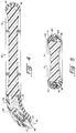
- the safety razor handle assembly 10 comprises a substantially flat planar body member 12 having a top shell member 14 and a bottom shell member 16 mounted on the opposite surfaces of the body member, as best shown in Figures 2 through 5.
- the body member 12 is manufactured of a substantially rigid plastic material such as a styrene and may be of a color or design which is attractive to the user employing the razor handle assembly 10.
- the top shell member 14 and bottom shell member 16 each are manufactured of a resilient plastic material such as ABS and as best shown in Figure 2, the bottom shell member 16 is provided with a plurality of upwardly projecting cylindrical pins 18 which extend through an equal number of aligned circular openings 19 in the body member 12.
- the upper portion of each of the pins 18 is formed to the configuration shown in Figure 5, producing a head 20 and locking the two members together.
- the body member 12 is provided with a plurality of slots 22, each having an outwardly extending flange 23 disposed in alignment with the opening.
- the top shell member 14 is provided with a plurality of downwardly extending detents 24, as best shown in Figure 4, in the same number as the slots 22 and aligned therewith such that when the top shell member 14 is placed onto the assembled body member 12 and bottom shell member 16, the detents 24 are snapped over the flanges 23 to secure the top shell member to the handle assembly 10.
- top shell member 14, body member 12 and bottom shell member 16 With the top shell member 14, body member 12 and bottom shell member 16 thus assembled, it will be observed that the shell members 14 and 16 extend only about the periphery of the body member 12 and therefore enable the body member to be of a colored material or of a designed surface which may be changed from time to time, while retaining the top shell member and bottom shell member assembly employed in the present construction. With the members thus, the body member 12 extends slightly beyond the top shell member 14 and bottom shell member 16 to provide a firm and rigid sandwich structure for the grasp of the user.
- top shell member 14 and bottom shell member 16 extend beyond the body member 12 and are curved downwardly at an angle of about 45° with the body member 12. That portion of the combined shell members 14 and 16 form a substantially enclosed housing 26 having a slotted opening 27 formed at the forwardmost end of the shell members 14 and 16 and a pair of slotted openings 28 and 29 formed at the sides of the housing.
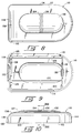
- a button assembly including a pair of buttons 30 and 31 are disposed within the housing 26 and are interconnected by a flexible web 32, the buttons 30 and 31 each extending through a respective slotted opening 28 and 29, as best seen in Figure 6.
- the button is generally manufactured of Nylon or similar material suitable for employment in the operative mechanism to be described below.
- a pair of bearing members 34 and 36 are disposed adjacent the slotted opening 27 and are movable toward and away from each other to accept a razor blade assembly for pivotal movement, as is well known in the art.
- the razor blade assembly for which the bearing members 34 and 36 are designed, as well as similar bearing members, are shown and described in U.S. Patent 4,492,025. Therefore, the bearing members and the related razor blade assembly will not be described in detail herein.
- the bearing members 34 and 36 are each formed on a pair of forwardly extending legs 38 and 40, respectively, which are interconnected by a flexible hinge 41 providing a unitary structure which is of one piece molded construction.
- a pair of laterally facing opposed surfaces 42 and 44 are disposed one on each of the legs 38 and 39 for contact with a respective button 30 or 31, and a V-shaped spring 45 is disposed between the legs 38 and 40 biasing the surfaces 42 and 44 against the buttons 30 and 31.
- Within the V-shaped spring 45 is located a plunger 46 having a pair of arms 47 and 48 which extend laterally and forwardly to contact a pair of detents 49 and 50 disposed on the legs 38 and 40.
- a helical spring 52 is received in a cylindrical opening in the base of the plunger 46 and extends rearwardly to contact the spring 45 and bias the plunger forwardly within the unitary assembly containing the legs 38 and 39.
- the operative elements of the razor handle assembly 10 are in the configuration shown in Figure 6 of the drawing when a blade assembly is not disposed on the razor handle, movement of the bearing members 34 and 36 toward one another being required for receiving a razor assembly for pivotal movement, as described in the aforementioned U.S. Patent 4,492,025.
- the V-shaped spring 45 is biasing the buttons 30 and 31 outwardly and the helical spring 52 is biasing the plunger 46 forwardly, the forward surface of the arms 47 and 48 contacting the detents 49 and 50.
- buttons 30 and 31 are pushed simultaneously inwardly and ride linearly inwardly guided by a pair of guide members 55 and 56 formed on the bottom shell 16, which are received in a pair of slots 57 and 58 formed in the buttons 30 and 31.
- FIG. 8 through 13 there is shown the cover 110 for retaining a dispenser (not shown) containing a plurality of safety razor blade cartridges.
- the dispenser is generally of the type shown in U.S. Design patent DES 316,962.
- the cover 110 comprises wall structure including a top wall 112, side walls 114 extending downwardly from the top wall 112 forming the right side wall and the rear wall of the cover 110 and terminating to provide a side opening 115 into a rectangular cavity 116 in the bottom of the cover.
- a front wall 118 contains an indentation 120 formed in the lower surface thereof which is generally provided for easy removal of a safety razor blade cartridge dispenser having a tab extending outwardly therefrom, which will be explained as the description proceeds.
- the cavity 116 is further formed by inner walls 122, 123 and 124 which provide a box-like structure in combination with a pair of ribs 126 and 127.
- the box-like structure is dimensioned to receive a blade dispenser of generally rectangular configuration therein and a pair of detents 128 and 129 on the wall 124 in combination with a single detent 130 disposed on the wall 122 are dimensioned and so spaced as to retain the blade dispenser within the cavity 116 with the blade dispenser resting on the ribs 126 and 127 and the opposite side of the dispenser firmly held within the detents 128, 129 and 130.
- the top wall 112 is formed of a substantially domed configuration having an elongated convex surface 132 centrally located on the upper surface of the top wall. Midway between the ends of the raised elongated surface 132 there is provided a pair of sinuous outwardly projecting ribs 134 and 136 extending laterally substantially entirely across the convex surface 132.
- the top wall 112 and the front wall 118 are joined by a radial surface 138 extending laterally across the width of the cover 110.
- the cover 110 is preferably manufactured of a T grade ABS material, however it should be understood that the cover may be fabricated from any of a plurality of similar plastic materials.
- the razor handle 10 comprises the flat planar body member 12 having a forward portion 104 extending downwardly forming an angle with the handle 10.
- the lower surface of the handle 10 is provided with a plurality of sinuous recesses 106 which are provided to offer a gripping surface for the user during the shaving process.
- Each of the recesses 106 is a mirror image of the sinuous ribs 134 and 136 provided on the cover 110 and are formed in a concave portion 108 of the razor, the concave portion 108 being of a dimension for nesting with the elongated convex surface 132 of the cover 110.
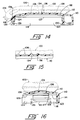
- the recesses 106 are of the same lateral extent as the ribs 134 and 136 however as best shown in Figure 14, there is one position wherein the ribs 134 and 136 mate with a corresponding pair of recesses 106 the two pairs of ribs and recesses falling into interfitting engagement when the lower surface of the forward portion 104 of the razor is in contact with the radial surface 138 of the cover and the concave portion 108 of the razor is properly located on the convex surface 132 of the cover 110. With the ribs 134 and 136 so located, the razor handle 10 is locked from movement in any direction in a plane parallel to the top wall 112 of the cover 110.
- the razor handle 10 cover 110 combination is now provided as a compact unit which may be packaged for shipment as a unit and may be stored as a compact unit by the user during the life of the razor, as shown in Figure 1.
- the ribs 134 and 136 are dimensions such that their fit with the recesses 106 does not provide a locking engagement in the vertical direction but merely a nesting of razor handle 10 and cover 110 which prevents movement in the direction of the plain of the top wall 112 of the cover. Thus, there is little likelihood that the user would attempt to employ the combination of razor handle 10 and cover 110 in the shaving process thereby wetting the unused blades retained within the cover.
- the pair of ribs 134 and 136 could be of a dimension to provide such locking engagement, and in addition more than two ribs could be provided to contact more than two recesses, if desired.
Landscapes
- Engineering & Computer Science (AREA)
- Life Sciences & Earth Sciences (AREA)
- Forests & Forestry (AREA)
- Mechanical Engineering (AREA)
- Manufacturing & Machinery (AREA)
- Packaging Of Annular Or Rod-Shaped Articles, Wearing Apparel, Cassettes, Or The Like (AREA)
- Knives (AREA)
- Insulated Conductors (AREA)
- Manufacture Of Macromolecular Shaped Articles (AREA)
- Packages (AREA)
- Pharmaceuticals Containing Other Organic And Inorganic Compounds (AREA)
- Medicines Containing Material From Animals Or Micro-Organisms (AREA)
Abstract
Description
Claims (4)
- A razor handle assembly (10) for receiving a razor blade assembly, said handle (10) comprising a substantially planar body, an opening (27) formed in the forward end of said handle (10) and a pair of bearing members (34, 36) adjacent said opening, said bearing members (34, 36) being movable by means disposed in the handle toward and away from each other and adapted pivotally to receive a razor blade assembly for pivotal movement on said handle, characterized in that the razor handle (10) is shaped to mate with a cartridge receiving and retaining cover and is formed by a substantially planar body member (12), a top shell member (14) mounted on one surface of the body member (12) and a bottom shell member (16) mounted on the opposite surface of said body member (12), each of said shell members covering only the peripheral top and bottom surface of said body member and having portions which extend forwardly beyond the body member (12) to form a housing (26), said opening (27) being in the forward end of said housing (26), and in that the bottom surface of the handle has a concave recess (108) in which a plurality of sinuous recesses (106) are formed to cooperate with corresponding projections on a cartridge receiving and retaining cover.
- A razor handle assembly according to claim 1, characterized in that the portions of the top and bottom shell members (14, 16) forming the housing (26) extend forwardly and downwardly beyond the body member (12) to form an angle therewith.
- A razor handle assembly according to claim 1 or claim 2, characterized in that a pair of openings (28, 29) are formed one on each side of the housing (26) and in that a pair of buttons (30, 31) extend one through each of said openings, each said button being movable inwardly into said housing (26) to cause the bearing member moving means to move said bearing members toward each other to release a razor blade assembly retained on said bearing members.
- A razor handle assembly according to claim 3, characterized in that each bearing member is formed on the forward end of a respective leg (38, 40) of a unitary blade attachment member, said legs (38, 40) being interconnected by a flexible hinge (41) of said blade attachment member, and in that a pair of laterally facing opposed surfaces (42, 44) is disposed one on each leg of said blade attachment member for contacting a respective button (30, 31).
Applications Claiming Priority (5)
| Application Number | Priority Date | Filing Date | Title |
|---|---|---|---|
| US721067 | 1991-06-26 | ||
| US07/721,067 US5157835A (en) | 1991-06-26 | 1991-06-26 | Safety razor handle assembly |
| US07/768,992 US5113586A (en) | 1991-09-30 | 1991-09-30 | Dispenser cover for cartridge |
| US768992 | 1991-09-30 | ||
| PCT/US1992/004084 WO1993000203A1 (en) | 1991-06-26 | 1992-05-14 | Women's shaver |
Publications (3)
| Publication Number | Publication Date |
|---|---|
| EP0551455A1 EP0551455A1 (en) | 1993-07-21 |
| EP0551455A4 EP0551455A4 (en) | 1993-12-08 |
| EP0551455B1 true EP0551455B1 (en) | 1998-07-15 |
Family
ID=27110362
Family Applications (1)
| Application Number | Title | Priority Date | Filing Date |
|---|---|---|---|
| EP92912202A Expired - Lifetime EP0551455B1 (en) | 1991-06-26 | 1992-05-14 | Women's shaver |
Country Status (12)
| Country | Link |
|---|---|
| EP (1) | EP0551455B1 (en) |
| JP (1) | JP3188458B2 (en) |
| KR (1) | KR100245830B1 (en) |
| AT (1) | ATE168310T1 (en) |
| AU (1) | AU661318B2 (en) |
| BR (1) | BR9205332A (en) |
| CA (1) | CA2089749C (en) |
| DE (1) | DE69226252T2 (en) |
| ES (1) | ES2118134T3 (en) |
| MX (1) | MX9203115A (en) |
| NZ (1) | NZ243217A (en) |
| WO (1) | WO1993000203A1 (en) |
Families Citing this family (3)
| Publication number | Priority date | Publication date | Assignee | Title |
|---|---|---|---|---|
| US5497551A (en) * | 1994-10-13 | 1996-03-12 | The Gillette Company | Razor handle assembly |
| US20140230256A1 (en) * | 2013-02-20 | 2014-08-21 | The Gillette Company | Hand held device |
| CN104866127A (en) * | 2014-02-25 | 2015-08-26 | 宸鸿科技(厦门)有限公司 | Anti-static touch panel |
Family Cites Families (9)
| Publication number | Priority date | Publication date | Assignee | Title |
|---|---|---|---|---|
| US2320807A (en) * | 1942-11-06 | 1943-06-01 | Remington Rand Inc | Shaver head guard |
| US3754376A (en) * | 1972-02-01 | 1973-08-28 | Texaco Inc | Inert gas stripping of contaminated water |
| US3878605A (en) * | 1972-12-11 | 1975-04-22 | Philip Morris Inc | Handle construction |
| FR2312334A1 (en) * | 1975-05-27 | 1976-12-24 | Philip Morris Inc | Moulded plastic handle for safety razor - is of rectangular plate form for gripping in hand and of density to enable razor to float on water(BR071276) |
| US4141445A (en) * | 1976-01-28 | 1979-02-27 | Korich George P | Blade cartridge storage cap and razor holder |
| US4285428A (en) * | 1976-08-27 | 1981-08-25 | Warner-Lambert Company | Razor cartridge dispenser |
| GB1566505A (en) * | 1977-02-02 | 1980-04-30 | Gillette Co | Safety razor |
| NL180634C (en) * | 1977-12-23 | 1987-04-01 | Duphar Int Res | INJECTION SYRINGE AND NEEDLE HOLDER FOR THIS. |
| US5050301A (en) * | 1990-09-19 | 1991-09-24 | The Gillette Company | Razor assembly |
-
1992
- 1992-05-14 AT AT92912202T patent/ATE168310T1/en not_active IP Right Cessation
- 1992-05-14 DE DE69226252T patent/DE69226252T2/en not_active Expired - Lifetime
- 1992-05-14 WO PCT/US1992/004084 patent/WO1993000203A1/en not_active Ceased
- 1992-05-14 ES ES92912202T patent/ES2118134T3/en not_active Expired - Lifetime
- 1992-05-14 AU AU19978/92A patent/AU661318B2/en not_active Ceased
- 1992-05-14 JP JP50145793A patent/JP3188458B2/en not_active Expired - Fee Related
- 1992-05-14 BR BR9205332A patent/BR9205332A/en not_active IP Right Cessation
- 1992-05-14 CA CA002089749A patent/CA2089749C/en not_active Expired - Fee Related
- 1992-05-14 EP EP92912202A patent/EP0551455B1/en not_active Expired - Lifetime
- 1992-06-19 NZ NZ243217A patent/NZ243217A/en unknown
- 1992-06-22 MX MX9203115A patent/MX9203115A/en unknown
-
1993
- 1993-02-25 KR KR1019930700564A patent/KR100245830B1/en not_active Expired - Fee Related
Also Published As
| Publication number | Publication date |
|---|---|
| EP0551455A1 (en) | 1993-07-21 |
| CA2089749A1 (en) | 1992-12-27 |
| ES2118134T3 (en) | 1998-09-16 |
| MX9203115A (en) | 1992-12-01 |
| JPH06500725A (en) | 1994-01-27 |
| DE69226252T2 (en) | 1999-02-18 |
| KR100245830B1 (en) | 2000-05-01 |
| ATE168310T1 (en) | 1998-08-15 |
| BR9205332A (en) | 1994-03-08 |
| CA2089749C (en) | 1999-07-20 |
| JP3188458B2 (en) | 2001-07-16 |
| DE69226252D1 (en) | 1998-08-20 |
| AU1997892A (en) | 1993-01-25 |
| EP0551455A4 (en) | 1993-12-08 |
| AU661318B2 (en) | 1995-07-20 |
| NZ243217A (en) | 1994-10-26 |
| WO1993000203A1 (en) | 1993-01-07 |
Similar Documents
| Publication | Publication Date | Title |
|---|---|---|
| US5157835A (en) | Safety razor handle assembly | |
| US5113586A (en) | Dispenser cover for cartridge | |
| KR100538753B1 (en) | Shaving razor | |
| US4258471A (en) | Razor handle | |
| EP0020816A1 (en) | Shaving razor assembly | |
| US4253237A (en) | Razor handle | |
| KR0132060B1 (en) | Shaver combined razor body and blade assembly | |
| US4347663A (en) | Safety razor having movable head | |
| US4253236A (en) | Razor blade assembly | |
| EP0395693B1 (en) | Retractable blade safety razor | |
| CA2373662A1 (en) | Shaving razor using blade cartridge and blade cartridge therefor | |
| CA2373228A1 (en) | Shaving razor with pivoting blade carrier and replaceable blade cartridge therefor | |
| KR20150095935A (en) | Shaver | |
| AU2006232128B2 (en) | Dispenser for razor cartridges | |
| GB2362849A (en) | Unitary spring clip for retaining a razor cartridge on a handle | |
| WO2014075844A1 (en) | Shaving systems | |
| CA2089749C (en) | Woman's shaver | |
| US4831730A (en) | Razor with stackable cartridge | |
| EP0020815A1 (en) | A razor handle | |
| JPH0540869Y2 (en) | ||
| JPS5833980Y2 (en) | handy razor | |
| JPS5833981Y2 (en) | handy razor |
Legal Events
| Date | Code | Title | Description |
|---|---|---|---|
| PUAI | Public reference made under article 153(3) epc to a published international application that has entered the european phase |
Free format text: ORIGINAL CODE: 0009012 |
|
| AK | Designated contracting states |
Kind code of ref document: A1 Designated state(s): AT BE CH DE ES FR GB IT LI LU NL |
|
| 17P | Request for examination filed |
Effective date: 19930622 |
|
| RAP1 | Party data changed (applicant data changed or rights of an application transferred) |
Owner name: THE GILLETTE COMPANY |
|
| RHK1 | Main classification (correction) |
Ipc: B26B 21/24 |
|
| A4 | Supplementary search report drawn up and despatched |
Effective date: 19931021 |
|
| AK | Designated contracting states |
Kind code of ref document: A4 Designated state(s): AT BE CH DE ES FR GB IT LI LU NL |
|
| 17Q | First examination report despatched |
Effective date: 19950214 |
|
| GRAG | Despatch of communication of intention to grant |
Free format text: ORIGINAL CODE: EPIDOS AGRA |
|
| GRAG | Despatch of communication of intention to grant |
Free format text: ORIGINAL CODE: EPIDOS AGRA |
|
| GRAH | Despatch of communication of intention to grant a patent |
Free format text: ORIGINAL CODE: EPIDOS IGRA |
|
| GRAH | Despatch of communication of intention to grant a patent |
Free format text: ORIGINAL CODE: EPIDOS IGRA |
|
| GRAA | (expected) grant |
Free format text: ORIGINAL CODE: 0009210 |
|
| AK | Designated contracting states |
Kind code of ref document: B1 Designated state(s): AT BE CH DE ES FR GB IT LI LU NL |
|
| REF | Corresponds to: |
Ref document number: 168310 Country of ref document: AT Date of ref document: 19980815 Kind code of ref document: T |
|
| REG | Reference to a national code |
Ref country code: CH Ref legal event code: NV Representative=s name: A. BRAUN, BRAUN, HERITIER, ESCHMANN AG PATENTANWAE Ref country code: CH Ref legal event code: EP |
|
| REF | Corresponds to: |
Ref document number: 69226252 Country of ref document: DE Date of ref document: 19980820 |
|
| REG | Reference to a national code |
Ref country code: ES Ref legal event code: FG2A Ref document number: 2118134 Country of ref document: ES Kind code of ref document: T3 |
|
| ET | Fr: translation filed | ||
| PG25 | Lapsed in a contracting state [announced via postgrant information from national office to epo] |
Ref country code: LU Free format text: LAPSE BECAUSE OF NON-PAYMENT OF DUE FEES Effective date: 19990514 Ref country code: AT Free format text: LAPSE BECAUSE OF NON-PAYMENT OF DUE FEES Effective date: 19990514 |
|
| PLBE | No opposition filed within time limit |
Free format text: ORIGINAL CODE: 0009261 |
|
| STAA | Information on the status of an ep patent application or granted ep patent |
Free format text: STATUS: NO OPPOSITION FILED WITHIN TIME LIMIT |
|
| PG25 | Lapsed in a contracting state [announced via postgrant information from national office to epo] |
Ref country code: LI Free format text: LAPSE BECAUSE OF NON-PAYMENT OF DUE FEES Effective date: 19990531 Ref country code: CH Free format text: LAPSE BECAUSE OF NON-PAYMENT OF DUE FEES Effective date: 19990531 Ref country code: BE Free format text: LAPSE BECAUSE OF NON-PAYMENT OF DUE FEES Effective date: 19990531 |
|
| 26N | No opposition filed | ||
| BERE | Be: lapsed |
Owner name: THE GILLETTE CY Effective date: 19990531 |
|
| REG | Reference to a national code |
Ref country code: CH Ref legal event code: PL |
|
| REG | Reference to a national code |
Ref country code: GB Ref legal event code: IF02 |
|
| PGFP | Annual fee paid to national office [announced via postgrant information from national office to epo] |
Ref country code: NL Payment date: 20070412 Year of fee payment: 16 |
|
| PGFP | Annual fee paid to national office [announced via postgrant information from national office to epo] |
Ref country code: ES Payment date: 20070516 Year of fee payment: 16 |
|
| PGFP | Annual fee paid to national office [announced via postgrant information from national office to epo] |
Ref country code: GB Payment date: 20070410 Year of fee payment: 16 |
|
| PGFP | Annual fee paid to national office [announced via postgrant information from national office to epo] |
Ref country code: IT Payment date: 20070519 Year of fee payment: 16 |
|
| PGFP | Annual fee paid to national office [announced via postgrant information from national office to epo] |
Ref country code: FR Payment date: 20070503 Year of fee payment: 16 |
|
| GBPC | Gb: european patent ceased through non-payment of renewal fee |
Effective date: 20080514 |
|
| PG25 | Lapsed in a contracting state [announced via postgrant information from national office to epo] |
Ref country code: NL Free format text: LAPSE BECAUSE OF NON-PAYMENT OF DUE FEES Effective date: 20081201 |
|
| REG | Reference to a national code |
Ref country code: FR Ref legal event code: ST Effective date: 20090119 |
|
| PG25 | Lapsed in a contracting state [announced via postgrant information from national office to epo] |
Ref country code: FR Free format text: LAPSE BECAUSE OF NON-PAYMENT OF DUE FEES Effective date: 20080602 |
|
| PG25 | Lapsed in a contracting state [announced via postgrant information from national office to epo] |
Ref country code: GB Free format text: LAPSE BECAUSE OF NON-PAYMENT OF DUE FEES Effective date: 20080514 |
|
| REG | Reference to a national code |
Ref country code: ES Ref legal event code: FD2A Effective date: 20080516 |
|
| PG25 | Lapsed in a contracting state [announced via postgrant information from national office to epo] |
Ref country code: IT Free format text: LAPSE BECAUSE OF NON-PAYMENT OF DUE FEES Effective date: 20080514 |
|
| PG25 | Lapsed in a contracting state [announced via postgrant information from national office to epo] |
Ref country code: ES Free format text: LAPSE BECAUSE OF NON-PAYMENT OF DUE FEES Effective date: 20080516 |
|
| PGFP | Annual fee paid to national office [announced via postgrant information from national office to epo] |
Ref country code: DE Payment date: 20110531 Year of fee payment: 20 |
|
| REG | Reference to a national code |
Ref country code: DE Ref legal event code: R071 Ref document number: 69226252 Country of ref document: DE |
|
| REG | Reference to a national code |
Ref country code: DE Ref legal event code: R071 Ref document number: 69226252 Country of ref document: DE |
|
| PG25 | Lapsed in a contracting state [announced via postgrant information from national office to epo] |
Ref country code: DE Free format text: LAPSE BECAUSE OF EXPIRATION OF PROTECTION Effective date: 20120515 |