EP0551441B1 - Multi-resonant nmr coils - Google Patents
Multi-resonant nmr coils Download PDFInfo
- Publication number
- EP0551441B1 EP0551441B1 EP92900978A EP92900978A EP0551441B1 EP 0551441 B1 EP0551441 B1 EP 0551441B1 EP 92900978 A EP92900978 A EP 92900978A EP 92900978 A EP92900978 A EP 92900978A EP 0551441 B1 EP0551441 B1 EP 0551441B1
- Authority
- EP
- European Patent Office
- Prior art keywords
- series
- elements
- frequency
- resonant
- circuit
- Prior art date
- Legal status (The legal status is an assumption and is not a legal conclusion. Google has not performed a legal analysis and makes no representation as to the accuracy of the status listed.)
- Expired - Lifetime
Links
- 239000003990 capacitor Substances 0.000 claims description 7
- 230000001939 inductive effect Effects 0.000 claims description 5
- 239000000523 sample Substances 0.000 description 14
- 230000004044 response Effects 0.000 description 7
- 230000005284 excitation Effects 0.000 description 6
- 238000005481 NMR spectroscopy Methods 0.000 description 4
- 230000003595 spectral effect Effects 0.000 description 4
- 238000002955 isolation Methods 0.000 description 3
- 230000005540 biological transmission Effects 0.000 description 2
- 230000008878 coupling Effects 0.000 description 2
- 238000010168 coupling process Methods 0.000 description 2
- 238000005859 coupling reaction Methods 0.000 description 2
- 230000001747 exhibiting effect Effects 0.000 description 2
- 238000012986 modification Methods 0.000 description 2
- 230000004048 modification Effects 0.000 description 2
- 238000012545 processing Methods 0.000 description 2
- 230000001052 transient effect Effects 0.000 description 2
- 238000012935 Averaging Methods 0.000 description 1
- OKTJSMMVPCPJKN-OUBTZVSYSA-N Carbon-13 Chemical compound [13C] OKTJSMMVPCPJKN-OUBTZVSYSA-N 0.000 description 1
- 241000282320 Panthera leo Species 0.000 description 1
- 238000004458 analytical method Methods 0.000 description 1
- 230000008901 benefit Effects 0.000 description 1
- 239000004020 conductor Substances 0.000 description 1
- 238000009826 distribution Methods 0.000 description 1
- 238000005315 distribution function Methods 0.000 description 1
- 230000009977 dual effect Effects 0.000 description 1
- 238000002474 experimental method Methods 0.000 description 1
- 229910052739 hydrogen Inorganic materials 0.000 description 1
- 239000001257 hydrogen Substances 0.000 description 1
- 238000003384 imaging method Methods 0.000 description 1
- 230000006698 induction Effects 0.000 description 1
- 238000012423 maintenance Methods 0.000 description 1
- 238000000034 method Methods 0.000 description 1
- 230000003534 oscillatory effect Effects 0.000 description 1
- 230000009466 transformation Effects 0.000 description 1
Images


Classifications
-
- G—PHYSICS
- G01—MEASURING; TESTING
- G01R—MEASURING ELECTRIC VARIABLES; MEASURING MAGNETIC VARIABLES
- G01R33/00—Arrangements or instruments for measuring magnetic variables
- G01R33/20—Arrangements or instruments for measuring magnetic variables involving magnetic resonance
- G01R33/28—Details of apparatus provided for in groups G01R33/44 - G01R33/64
- G01R33/32—Excitation or detection systems, e.g. using radio frequency signals
- G01R33/36—Electrical details, e.g. matching or coupling of the coil to the receiver
- G01R33/3628—Tuning/matching of the transmit/receive coil
- G01R33/3635—Multi-frequency operation
Definitions
- the invention is in the area of NMR probe circuits and particularly such probe circuits exhibiting multiple-tuned response.
- a double-tuned circuit often utilizes a single inductor common to two resonant circuits.
- Each sub-circuit in such an arrangement is separately tuned and impedance matched to its respective rf source (or sink).
- rf source or sink
- the necessity for plural, isolated ports may be less for resonance observation than for resonance excitation.
- Double-tuned circuits which employ a transmission line of length ⁇ /4 (at the high frequency) to provide such isolation.
- ⁇ /4 at the high frequency
- a combination of 1 ⁇ 2 ⁇ transmission lines has been used to provide a double-tuned arrangement for frequencies in a ratio of a power of two to form a series arrangement of separate inductors at one frequency and a parallel arrangement of the same inductors at another frequency. This work is discussed in USSN 477,687, commonly assigned.
- Inductive elements in rf probe circuits are known to include "split inductors" such as taught in the work of Alderman and Grant, J. Mag. Res., v. 36, pp. 447-451 (1979) and Cook and Lowe, J. Mag. Res., v. 49, p. 346 (1982).
- Balanced circuits exhibiting electrical symmetry are also known for the purpose of supporting double-tuned apparatus. Such circuits exhibit, among other properties, the virtue that a symmetry plane (or other surface) is defined which has a property of electrical neutrality, which is to say, a virtual ground.
- US-A-4,792,759 discloses a circuit resonant at two non-adjacent frequencies comprising a plurality of lumped LC elements connected in series. These elements include an LC series element and an LC parallel element. J. Magn. Res. 89 (1990) pp 41-50, J. Magn. Res. 74 (1987) pp 147-154 and US-A-4,742,304 described similar circuits.
- the present invention is set out in claim 1.
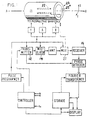
- FIG. 1 Portions of a typical NMR data acquisition instrument are schematically illustrated on FIG. 1.
- An acquisition/control processor communicates with an rf transmitter 12 and modulator 14.
- the modulated rf power irradiates an object (not shown) in a magnetic field 21 through a multiplexer 27 and probe assembly 22 and the response of the object is intercepted by probe 22 communicating with receiver 16.
- the response typically takes the form of a transient oscillatory signal, or free induction decay.
- This transient waveform is sampled at regular intervals and samples are digitized. The digitized time domain waveform is then subject to further processing.
- the nature of such processing may include averaging a time domain waveform with a number of nominally identical such waveforms, and transformation of the average time domain waveform to the frequency domain yields a spectral distribution function directed to an output device.
- the latter may take on any of a number of identities for the display of further data and analysis.
- the magnetic field 21 which polarizes a sample is established by an appropriate means indicated in FIG. 1 such as cryostat 23 for the establishment and maintenance of a superconducting phase in a saddle coil, not shown.
- the cryostat comprises a bore 23A in which the probe and sample are housed at room temperature.
- FIG. 2 there is shown a saddle coil of prior art, unrolled or mapped onto plane.
- this arrangement is disposed on the wall of a cylinder whereby points A and B coincide and the rf source is applied at point C.
- the saddle coil is often disposed within a unipotential outer cylindrical conductor (shield).
- the equivalent circuit is shown in either of FIGs. 3a or 3b where C p is the effective capacitance to the shield.
- the effective circuit in FIG. 3b is modified by shunting each series capacitor C c with an inductor L s where the impedance presented by L s is much greater than the impedance of C c at the high frequency, and the impedance of L c is much less than the impedance presented by C c at the lower frequency.
- the addition of series capacitor C s provides the ability to tune to a desired series resonant condition.
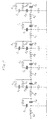
- FIG. 4A A three section example of the present invention following this embodiment is shown in FIG. 4A.
- a tune and match capacitor combination 21 may be employed to tune the coil to a relatively low frequency because the impedance of the C s -L s combination effectively shorts out C c at the low frequency resonance.
- FIG. 4B there is shown an example of slight modification to the saddle coil of FIG. 4A to present a balanced pair of rf isolated ports for concurrent excitation.
- the tune and match combination 21 is eliminated (or further simplified) because each port is carefully matched to its external source/sink.
- the multiplicity of circuit resonances can be expanded beyond double-tuned response by adding series resonant combinations in parallel with corresponding sections.
Landscapes
- Physics & Mathematics (AREA)
- Condensed Matter Physics & Semiconductors (AREA)
- General Physics & Mathematics (AREA)
- Magnetic Resonance Imaging Apparatus (AREA)
Description
Claims (2)
- A circuit resonant at two non-adjacent frequencies ω1 and ω2 comprising a plurality of LC elements, characterised in that said elements comprise:(a) a plurality of first LC series elements, each said element in series relationship, an initial said LC series element receiving rf power and a final said LC series element connected to ground, said LC series elements each comprising an inductive member (LC; LH) in series with a capacitive member (CC; CH);(b) shunt means arranged in parallel with each said capacitive member (CC; CH), said shunt means comprising a second LC series element, said second LC series element comprising a capacitive element (CS; CL) in series relation with an inductive member (LS; LL), whereby said first LC series elements present a low impedance to a first selected frequency ω1 and a high impedance to a second selected frequency ω2 and said second LC series elements present a high impedance to said first frequency and a low impedance to said second frequency.
- A circuit as claimed in claim 1 wherein for alternate capacitive members of the first LC series elements the shunt means further comprises a further LC series element, the capacitor (CI) of the further LC series element being connected between the capacitor (CH) of the first LC series element and the capacitor (CL) of the second LC series element, and the inductor (LI) of the further LC series element being connected in parallel with the second LC series element.
Applications Claiming Priority (3)
| Application Number | Priority Date | Filing Date | Title |
|---|---|---|---|
| US07/603,966 US5166621A (en) | 1990-10-26 | 1990-10-26 | Multi-resonant nmr coils |
| PCT/US1991/007901 WO1992008146A1 (en) | 1990-10-26 | 1991-10-24 | Multi-resonant nmr coils |
| US603966 | 1996-02-20 |
Publications (3)
| Publication Number | Publication Date |
|---|---|
| EP0551441A1 EP0551441A1 (en) | 1993-07-21 |
| EP0551441A4 EP0551441A4 (en) | 1993-10-27 |
| EP0551441B1 true EP0551441B1 (en) | 1998-01-21 |
Family
ID=24417624
Family Applications (1)
| Application Number | Title | Priority Date | Filing Date |
|---|---|---|---|
| EP92900978A Expired - Lifetime EP0551441B1 (en) | 1990-10-26 | 1991-10-24 | Multi-resonant nmr coils |
Country Status (5)
| Country | Link |
|---|---|
| US (1) | US5166621A (en) |
| EP (1) | EP0551441B1 (en) |
| JP (1) | JP3157157B2 (en) |
| DE (1) | DE69128792T2 (en) |
| WO (1) | WO1992008146A1 (en) |
Families Citing this family (16)
| Publication number | Priority date | Publication date | Assignee | Title |
|---|---|---|---|---|
| US6026311A (en) * | 1993-05-28 | 2000-02-15 | Superconductor Technologies, Inc. | High temperature superconducting structures and methods for high Q, reduced intermodulation resonators and filters |
| US7231238B2 (en) | 1989-01-13 | 2007-06-12 | Superconductor Technologies, Inc. | High temperature spiral snake superconducting resonator having wider runs with higher current density |
| JPH06224644A (en) * | 1993-01-25 | 1994-08-12 | Nec Corp | Semiconductor device |
| DE4333182A1 (en) * | 1993-09-29 | 1995-03-30 | Siemens Ag | Double-resonant antenna arrangement for a magnetic resonance instrument |
| US5424645A (en) * | 1993-11-18 | 1995-06-13 | Doty Scientific, Inc. | Doubly broadband triple resonance or quad resonance NMR probe circuit |
| GB2340681B (en) * | 1998-08-14 | 2003-07-30 | Mars Inc | Oscillators |
| US20030222732A1 (en) * | 2002-05-29 | 2003-12-04 | Superconductor Technologies, Inc. | Narrow-band filters with zig-zag hairpin resonator |
| US6933725B2 (en) * | 2004-01-16 | 2005-08-23 | Bruker Biospin Corporation | NMR probe circuit for generating close frequency resonances |
| US7132829B2 (en) * | 2005-01-18 | 2006-11-07 | Varian, Inc. | NMR RF coils with improved low-frequency efficiency |
| US7064549B1 (en) * | 2005-01-18 | 2006-06-20 | Varian, Inc. | NMR RF coils with split movable capacitance bands |
| JP4702178B2 (en) * | 2006-05-19 | 2011-06-15 | ソニー株式会社 | Semiconductor coupling device, semiconductor element, and high-frequency module |
| JP4506722B2 (en) * | 2006-05-19 | 2010-07-21 | ソニー株式会社 | Semiconductor element coupling device, semiconductor element, high-frequency module, and semiconductor element coupling method |
| DE102010044187B4 (en) * | 2010-11-19 | 2013-10-31 | Siemens Aktiengesellschaft | Local coil for a magnetic resonance device and magnetic resonance device |
| CN102624351A (en) * | 2012-04-06 | 2012-08-01 | 重庆大学 | Multi-frequency resonance circuit |
| US10761159B2 (en) | 2017-03-01 | 2020-09-01 | Scanmed, Llc | Dual tuned MRI resonator and coil package and method |
| US11493579B2 (en) | 2018-09-24 | 2022-11-08 | Quality Electrodynamics, Llc | Multi-tune magnetic resonance imaging (MRI) coil using different matching impedances |
Family Cites Families (13)
| Publication number | Priority date | Publication date | Assignee | Title |
|---|---|---|---|---|
| US3098208A (en) * | 1958-09-29 | 1963-07-16 | Gen Electric | Coupling circuit for connecting together two resonant circuits and tuning the whole over a band of frequencies |
| US3434043A (en) * | 1966-02-14 | 1969-03-18 | Varian Associates | Nuclear magnetic resonance probe apparatus having double tuned coil systems for spectrometers employing an internal reference |
| US4742304A (en) * | 1986-05-02 | 1988-05-03 | Phospho-Energetics, Inc. | Multiple tuning NMR probe |
| NL8603252A (en) * | 1986-12-22 | 1988-07-18 | Philips Nv | MAGNETIC RESONANCE DEVICE WITH CONVENIENT RF COIL. |
| US4792759A (en) * | 1987-07-29 | 1988-12-20 | Elscint Ltd. | Multi-frequency surface probe |
| JPS6443241A (en) * | 1987-08-10 | 1989-02-15 | Toshiba Corp | Probe coil apparatus for magnetic resonance imaging apparatus |
| US4812764A (en) * | 1988-03-31 | 1989-03-14 | Varian Associates, Inc. | Calibrated decoupling of tightly coupled concentric surface coils |
| US4833412A (en) * | 1988-04-08 | 1989-05-23 | Varian Associates, Inc. | Double tuned circuit for distributed lumped capacitance observe coils |
| NL8801077A (en) * | 1988-04-26 | 1989-11-16 | Philips Nv | MAGNETIC RESONANCE DEVICE WITH DISCONNECTED RF COILS. |
| US4916418A (en) * | 1989-03-31 | 1990-04-10 | Varian Associates, Inc. | Double tuned bird cage coil |
| US5041790A (en) * | 1990-01-16 | 1991-08-20 | Toshiba America Mri, Inc. | Dual-tuned RF coil for MRI spectroscopy |
| US5038105A (en) * | 1990-02-09 | 1991-08-06 | Spectroscopy Imaging Systems Corporation | Series/parallel double-tuned NMR coils |
| US5057778A (en) * | 1990-03-29 | 1991-10-15 | Spectroscopy Imaging Systems Corporation | Double tuned nmr coils |
-
1990
- 1990-10-26 US US07/603,966 patent/US5166621A/en not_active Expired - Lifetime
-
1991
- 1991-10-24 DE DE69128792T patent/DE69128792T2/en not_active Expired - Lifetime
- 1991-10-24 JP JP50081292A patent/JP3157157B2/en not_active Expired - Lifetime
- 1991-10-24 WO PCT/US1991/007901 patent/WO1992008146A1/en not_active Ceased
- 1991-10-24 EP EP92900978A patent/EP0551441B1/en not_active Expired - Lifetime
Also Published As
| Publication number | Publication date |
|---|---|
| EP0551441A4 (en) | 1993-10-27 |
| DE69128792T2 (en) | 1998-05-28 |
| EP0551441A1 (en) | 1993-07-21 |
| JPH06502919A (en) | 1994-03-31 |
| WO1992008146A1 (en) | 1992-05-14 |
| DE69128792D1 (en) | 1998-02-26 |
| JP3157157B2 (en) | 2001-04-16 |
| US5166621A (en) | 1992-11-24 |
Similar Documents
| Publication | Publication Date | Title |
|---|---|---|
| US5057778A (en) | Double tuned nmr coils | |
| US5243289A (en) | Multiply-tuned probe for magnetic resonance imaging or spectroscopy | |
| Barberi et al. | A transmit‐only/receive‐only (TORO) RF system for high‐field MRI/MRS applications | |
| US4916398A (en) | Efficient remote transmission line probe tuning for NMR apparatus | |
| US4833412A (en) | Double tuned circuit for distributed lumped capacitance observe coils | |
| US5166621A (en) | Multi-resonant nmr coils | |
| US7973531B2 (en) | Detuning a radio-frequency coil | |
| US4446431A (en) | Double-tuned single coil probe for nuclear magnetic resonance spectrometer | |
| Wright et al. | Arrays of mutually coupled receiver coils: theory and application | |
| US4812764A (en) | Calibrated decoupling of tightly coupled concentric surface coils | |
| US5038105A (en) | Series/parallel double-tuned NMR coils | |
| US5329233A (en) | Cylindrical local coil for nuclear magnetic resonance imaging | |
| US5162739A (en) | Balanced multi-tuned high-power broadband coil for nmr | |
| EP0312586B1 (en) | Spurious resonance control for nmr observe coils | |
| JPH08252237A (en) | Magnetic resonance diagnostic device | |
| EP1247114B1 (en) | Superconductive networks to optimize multiply tuned nmr coils |
Legal Events
| Date | Code | Title | Description |
|---|---|---|---|
| PUAI | Public reference made under article 153(3) epc to a published international application that has entered the european phase |
Free format text: ORIGINAL CODE: 0009012 |
|
| 17P | Request for examination filed |
Effective date: 19930504 |
|
| AK | Designated contracting states |
Kind code of ref document: A1 Designated state(s): CH DE FR GB LI NL |
|
| A4 | Supplementary search report drawn up and despatched |
Effective date: 19930908 |
|
| AK | Designated contracting states |
Kind code of ref document: A4 Designated state(s): CH DE FR GB LI NL |
|
| 17Q | First examination report despatched |
Effective date: 19950516 |
|
| GRAG | Despatch of communication of intention to grant |
Free format text: ORIGINAL CODE: EPIDOS AGRA |
|
| GRAG | Despatch of communication of intention to grant |
Free format text: ORIGINAL CODE: EPIDOS AGRA |
|
| GRAH | Despatch of communication of intention to grant a patent |
Free format text: ORIGINAL CODE: EPIDOS IGRA |
|
| GRAH | Despatch of communication of intention to grant a patent |
Free format text: ORIGINAL CODE: EPIDOS IGRA |
|
| GRAA | (expected) grant |
Free format text: ORIGINAL CODE: 0009210 |
|
| AK | Designated contracting states |
Kind code of ref document: B1 Designated state(s): CH DE FR GB LI NL |
|
| REG | Reference to a national code |
Ref country code: CH Ref legal event code: EP |
|
| REF | Corresponds to: |
Ref document number: 69128792 Country of ref document: DE Date of ref document: 19980226 |
|
| REG | Reference to a national code |
Ref country code: CH Ref legal event code: NV Representative=s name: BOVARD AG PATENTANWAELTE |
|
| ET | Fr: translation filed | ||
| PGFP | Annual fee paid to national office [announced via postgrant information from national office to epo] |
Ref country code: FR Payment date: 19980930 Year of fee payment: 8 |
|
| PGFP | Annual fee paid to national office [announced via postgrant information from national office to epo] |
Ref country code: CH Payment date: 19981019 Year of fee payment: 8 |
|
| PLBE | No opposition filed within time limit |
Free format text: ORIGINAL CODE: 0009261 |
|
| STAA | Information on the status of an ep patent application or granted ep patent |
Free format text: STATUS: NO OPPOSITION FILED WITHIN TIME LIMIT |
|
| 26N | No opposition filed | ||
| PG25 | Lapsed in a contracting state [announced via postgrant information from national office to epo] |
Ref country code: LI Free format text: LAPSE BECAUSE OF NON-PAYMENT OF DUE FEES Effective date: 19991031 Ref country code: CH Free format text: LAPSE BECAUSE OF NON-PAYMENT OF DUE FEES Effective date: 19991031 |
|
| REG | Reference to a national code |
Ref country code: CH Ref legal event code: PL |
|
| PG25 | Lapsed in a contracting state [announced via postgrant information from national office to epo] |
Ref country code: FR Free format text: LAPSE BECAUSE OF NON-PAYMENT OF DUE FEES Effective date: 20000630 |
|
| REG | Reference to a national code |
Ref country code: FR Ref legal event code: ST |
|
| REG | Reference to a national code |
Ref country code: GB Ref legal event code: IF02 |
|
| PGFP | Annual fee paid to national office [announced via postgrant information from national office to epo] |
Ref country code: NL Payment date: 20101024 Year of fee payment: 20 |
|
| PGFP | Annual fee paid to national office [announced via postgrant information from national office to epo] |
Ref country code: DE Payment date: 20101027 Year of fee payment: 20 |
|
| PGFP | Annual fee paid to national office [announced via postgrant information from national office to epo] |
Ref country code: GB Payment date: 20101025 Year of fee payment: 20 |
|
| REG | Reference to a national code |
Ref country code: DE Ref legal event code: R071 Ref document number: 69128792 Country of ref document: DE |
|
| REG | Reference to a national code |
Ref country code: DE Ref legal event code: R071 Ref document number: 69128792 Country of ref document: DE |
|
| REG | Reference to a national code |
Ref country code: NL Ref legal event code: V4 Effective date: 20111024 |
|
| REG | Reference to a national code |
Ref country code: GB Ref legal event code: PE20 Expiry date: 20111023 |
|
| PG25 | Lapsed in a contracting state [announced via postgrant information from national office to epo] |
Ref country code: NL Free format text: LAPSE BECAUSE OF EXPIRATION OF PROTECTION Effective date: 20111024 |
|
| PG25 | Lapsed in a contracting state [announced via postgrant information from national office to epo] |
Ref country code: GB Free format text: LAPSE BECAUSE OF EXPIRATION OF PROTECTION Effective date: 20111023 |
|
| PG25 | Lapsed in a contracting state [announced via postgrant information from national office to epo] |
Ref country code: DE Free format text: LAPSE BECAUSE OF EXPIRATION OF PROTECTION Effective date: 20111025 |