EP0550897B1 - Microwave oven door control device - Google Patents
Microwave oven door control device Download PDFInfo
- Publication number
- EP0550897B1 EP0550897B1 EP92122034A EP92122034A EP0550897B1 EP 0550897 B1 EP0550897 B1 EP 0550897B1 EP 92122034 A EP92122034 A EP 92122034A EP 92122034 A EP92122034 A EP 92122034A EP 0550897 B1 EP0550897 B1 EP 0550897B1
- Authority
- EP
- European Patent Office
- Prior art keywords
- door
- signal
- microwave oven
- electromagnet
- response
- Prior art date
- Legal status (The legal status is an assumption and is not a legal conclusion. Google has not performed a legal analysis and makes no representation as to the accuracy of the status listed.)
- Expired - Lifetime
Links
- 238000012545 processing Methods 0.000 claims description 23
- 238000010438 heat treatment Methods 0.000 claims description 12
- 239000000696 magnetic material Substances 0.000 claims description 9
- 230000005294 ferromagnetic effect Effects 0.000 claims description 3
- 230000001846 repelling effect Effects 0.000 description 4
- LPXPTNMVRIOKMN-UHFFFAOYSA-M sodium nitrite Substances [Na+].[O-]N=O LPXPTNMVRIOKMN-UHFFFAOYSA-M 0.000 description 3
- 239000004334 sorbic acid Substances 0.000 description 3
- 238000013459 approach Methods 0.000 description 2
- 238000010586 diagram Methods 0.000 description 2
- 238000002474 experimental method Methods 0.000 description 2
- 238000000034 method Methods 0.000 description 2
- 230000005855 radiation Effects 0.000 description 2
- 238000010276 construction Methods 0.000 description 1
- 230000003247 decreasing effect Effects 0.000 description 1
- 230000001419 dependent effect Effects 0.000 description 1
- 230000000694 effects Effects 0.000 description 1
- 230000005670 electromagnetic radiation Effects 0.000 description 1
- 238000012986 modification Methods 0.000 description 1
- 230000004048 modification Effects 0.000 description 1
- 230000003287 optical effect Effects 0.000 description 1
- 239000000126 substance Substances 0.000 description 1
Images


Classifications
-
- F—MECHANICAL ENGINEERING; LIGHTING; HEATING; WEAPONS; BLASTING
- F24—HEATING; RANGES; VENTILATING
- F24C—DOMESTIC STOVES OR RANGES ; DETAILS OF DOMESTIC STOVES OR RANGES, OF GENERAL APPLICATION
- F24C15/00—Details
- F24C15/02—Doors specially adapted for stoves or ranges
-
- H—ELECTRICITY
- H05—ELECTRIC TECHNIQUES NOT OTHERWISE PROVIDED FOR
- H05B—ELECTRIC HEATING; ELECTRIC LIGHT SOURCES NOT OTHERWISE PROVIDED FOR; CIRCUIT ARRANGEMENTS FOR ELECTRIC LIGHT SOURCES, IN GENERAL
- H05B6/00—Heating by electric, magnetic or electromagnetic fields
- H05B6/64—Heating using microwaves
- H05B6/6414—Aspects relating to the door of the microwave heating apparatus
- H05B6/6417—Door interlocks of the microwave heating apparatus and related circuits
-
- F—MECHANICAL ENGINEERING; LIGHTING; HEATING; WEAPONS; BLASTING
- F24—HEATING; RANGES; VENTILATING
- F24C—DOMESTIC STOVES OR RANGES ; DETAILS OF DOMESTIC STOVES OR RANGES, OF GENERAL APPLICATION
- F24C7/00—Stoves or ranges heated by electric energy
- F24C7/08—Arrangement or mounting of control or safety devices
-
- G—PHYSICS
- G07—CHECKING-DEVICES
- G07C—TIME OR ATTENDANCE REGISTERS; REGISTERING OR INDICATING THE WORKING OF MACHINES; GENERATING RANDOM NUMBERS; VOTING OR LOTTERY APPARATUS; ARRANGEMENTS, SYSTEMS OR APPARATUS FOR CHECKING NOT PROVIDED FOR ELSEWHERE
- G07C9/00—Individual registration on entry or exit
- G07C9/00174—Electronically operated locks; Circuits therefor; Nonmechanical keys therefor, e.g. passive or active electrical keys or other data carriers without mechanical keys
- G07C9/00658—Electronically operated locks; Circuits therefor; Nonmechanical keys therefor, e.g. passive or active electrical keys or other data carriers without mechanical keys operated by passive electrical keys
- G07C9/00722—Electronically operated locks; Circuits therefor; Nonmechanical keys therefor, e.g. passive or active electrical keys or other data carriers without mechanical keys operated by passive electrical keys with magnetic components, e.g. magnets, magnetic strips, metallic inserts
Definitions
- the present invention relates to a microwave oven; and is more particularly concerned with a microwave oven door control device capable of accurately detecting a faulty state of the door and facilitating the latching and the opening operations of the door and starts from DE-A-38 40 650.
- a microwave oven has a door to provide a user access to the interior(cavity) of the microwave oven.
- the door also prevents the leakage of electromagnetic radiation during the operation of the microwave oven.
- a typical present day microwave oven employs hook-type door latches and slots on an oven wall in order to keep its door closed once the door is in the closed position.
- the door latches are usually secured in the locked position during the heating operation by means of mechanical locking structure or electrically actuated locking structure employing a solenoid.
- the microwave oven also has a mechanical or optical switch(or switches) which tells a closed state from an open state. The microwave oven can initiate and continue the heating operation only when the door is in the closed position. Two such arrangements are disclosed in U.S. Patent No. 3,733,456 issued to Louis W. Blackburn and Japanese Patent Laid-open Publication No. 60-33207.
- DE-A-3 840 650 describes a microwave oven according to the preamble of new claim 1.
- This microwave oven comprises electromagnetic means for detecting the state of the door, i.e. if the door is closed or open.
- a permanent magnet is provided at the microwave oven door and disposed so as to get into contact with a corresponding electromagnet installed at the housing of the microwave oven.
- the door is closed or opened currents are induced into the electromagnet.
- the induced currents are used as information about the opened or closed state of the door.
- this technique has no effect on the physical forces necessary to close or open the door.
- the known microwave oven uses a complicated technique based on high frequency a.c. signals applied to transmitter and receiver coils.
- a problem with such arrangements is that it is difficult and cumbersome to equip a microwave oven door with the door latches and it is also cumbersome to form the slots on a oven wall.
- an object of the present invention to provide a microwave oven with a novel oven door latching/ opening means which uses magnetic materials(e.g., ferromagnetics or permanent magnets) and electromagnets in place of hook-type door latches and slots on a oven wall.
- magnetic materials e.g., ferromagnetics or permanent magnets
- electromagnets in place of hook-type door latches and slots on a oven wall.
- Another object is to provide such door latching/opening means which can be fabricated readily and relatively economically, and which has a durable operability.
- the present invention provides a microwave oven with an automatic door control device, which comprises: an enclosure having therein a heating chamber adapted to receive an object to be heated; a door mounted at an opening of the heating chamber; at least one magnetic material provided at one side of the door; at least one electromagnet provided on the enclosure and adapted to contact with the magnetic material; at least one door state detecting means connected with the electromagnet for generating a first signal based on electromotive forces, said electromotive forces being generated in the electromagnet when the door is being closed or opened; a door open switch means for generating a second signal, said second signal being generated upon pressing a door open switch; a processing means for generating a control signal in response to the first signal and the second signal; at least one door latching and opening means connected with the electromagnet for latching and opening the door in response to the control signal, said door being latched while an electric current is applied to said electromagnet in one direction and opened when another current is applied to the electromagnet in another direction; a microwave energy generator
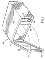
- the enclosure case 10 comprises a heating chamber 11 wherein an object to be heated such as food is to be placed.
- the heating chamber 11 has a door 12 mounted by means of, e.g., hinges 13 at one e.g., left, side portion of the enclosure case 10.
- a control panel 14 on which a display unit 5 and control switches SW(e.g., a start/stop switch, a door open switch, etc.) may be located is provided at the other, e.g., right, side portion of the enclosure case 10.
- magnetic materials e.g., ferromagnetics or permanent magnets
- 20' are provided at one side, for example, at the right side portion of the door 12 and disposed so as to contact with the corresponding electromagnets 30,30' installed in the enclosure case 10.
- the user places an object to be heated into the heating chamber 11 and then, closes the oven door 12.
- the permanent magnets 20,20' gets closer to the electromagnets 30,30' and as a result, currents are induced in the coils of the electromagnets 30,30'.
- the induced currents are used by a control circuit to detect the two closing stages of the door(i.e., when the door is being closed; and when the door is completely closed).
- the control circuit will apply currents in one direction to the coils of the electromagnets 30,30' to introduce attracting forces between the permanent magnets 20,20' and the electromagnets 30,30' until either an expected(i.e., opening by pressing the door open switch) or an unexpected (i.e., opening by physical forces) opening of the door happens. Accordingly, the door can be magnetically latched once the door has been closed.
- pressing the start/stop switch will initiate/end the radiation of microwaves within the heating chamber 11.
- An energy generator for the generation of microwaves under the control of the control circuit, can radiate microwaves only while the door is in the properly closed state. That is, when the door is not completely closed, the energy generator will not be initiated even if the start/stop switch is pressed. And when either the expected or the unexpected opening happens, the energy generator once initiated will stop its microwave radiating operation.
- the permanent magnets 20,20' When the door is being opened expectedly or unexpectedly, the permanent magnets 20,20' will gradually become distanced from the electromagnets 30,30'; and, as a result, currents are induced in the coils of the electromagnets 30,30' in the opposite direction to the previous one.
- the induced currents are used by the control circuit to detect the two opening stages of the door (i.e., when the door is being opened; and when the door is completely opened).
- control circuit will generate a buzzer sound with an appropriate indication on the display unit 5 when: the door is not completely closed; the door is being opened unexpectedly; or the door is not completely opened upon the pressing of the door open switch .
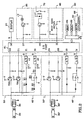
- Fig. 2 shows the control circuit diagram of an exemplary embodiment of the present invention.
- each of the electromagnets 30,30' is connected with the door state detecting means 40 or 40' and the door latching/opening means 50 or 50'.
- the door state detecting means 40(40') is also connected to the lines I 1 (I 3 ) and I2(I 4 ) of the I/O port 61 of the processing means 60.
- the door latching/opening means 50(50') is also connected to the lines O 1 (O 2 ) and O 2 (O 4 ) of the I/O port 61.
- the door state detecting means 40 preferably comprises a diode D 1 , a resistor R 1 , a condenser C 1 and an A/D converter 41 in one part and a diode D 2 , resistors R 2 ,R 3 ,R 4 , a condenser C 2 , an amplifier OP 1 , and an A/D converter 42 in the other part as shown in Fig. 2.
- Figs. 2 and 3 the operations of the door state detecting means 40 will now be fully described. In the first place, we will assume the oven door is being closed. As the door is being closed, the permament magnet 20 with the pole directions shown in Figs.
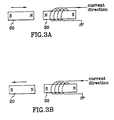
- the electromagnet 30 approaches the electromagnet 30; and, as a result, electric current is induced in the coil of the electromagnet 30 in the direction shown in Fig. 3A.
- the induced current will flow from the coil to the A/D converter 41 through the diode D 1 , the resistor R 1 and the condenser C 1 .
- the voltage across the condenser C 1 will be applied to the A/D converter 41 as an input votage thereof.
- the induced emf(electromotive force) will gradually be increased and so will the voltage across the condenser C 1 . Accordingly, the voltage has its peak value at the point of time just before the permanent magnet 20 contacts with the electromagnet 30.
- the A/D converter 41 then converts the time-varying analog input voltage signal to the appropriate bits (for example, 8 bits) of a digital signal.
- the resulting bits of digital signal will be sent in parallel through the line I 1 to the processing means 60 which will be described later.
- the absolute value of the induced emf will gradually be decreased until zero and so will the voltage across the condenser C 2 . Accordingly, the voltage has its peak value at the point of time when the permanent magnet 20 has just departed from the electromagnet 30.
- the A/D converter 42 then converts the time-varying analog input voltage signal to the appropriate bits of a digital signal. The resulting bits of digital signal will also be sent in parallel through the line I 2 to the processing means 60.
- the door latching/opening means 50 preferably comprises two transistors TR 1 , TR 2 .
- the base of the TR 1 is connected with the line O 1 of the I/O port 61 while its emitter is connected with the coil of the electromagnet 30. Accordingly, when an output signal at the line O 1 is high, the transistor TR 1 will be turned on. As a result, electric current will flow from a voltage source V to the ground through the coil of the electromagnet 30, which will introduce attracting forces between the permanent magnet 20 and the electromagnet 30. Therefore, the oven door can be magnetically latched by the output signal from the processing means 60 once the door has been closed.
- the base of the TR 2 is connected with the line O 2 of the I/O port 61 while its collector is connected with the coil of the electromagnet 30. Accordingly, when the output signal at the line O 2 is high, the transistor TR 2 will be turned on. As a result, electric current will flow from the ground to a voltage source -V through the coil of the electromagnet 30, which will introduce repelling forces between the permanent magnet 20 and the electromagnet 30. Therefore, the oven door can be opened by the output signal from the processing means 60 upon the pressing of the door open switch.
- a load driving power switching means 70 is shown on the right side to the I/O port 61.
- the switching means 70 comprises two resistors, a relay and a transistor whose base is connected to the line O 5 of the I/O port 61. Accordingly, as far as the output signal at the line O 5 is held high, the transistor becomes turned on and the relay makes its contact. Thereby, the switching means 70 controllably connects an AC source (not shown) to the loads(e.g., microwave generator, fan, motor, etc. also not shown) of the microwave oven. That is to say, in the event of a faulty situation i.e., when the oven door is not completely closed or when the door is opened expectedly or unexpectedly, the output signal at the line O 5 becomes low, which will disconnect the AC source from the loads.
- the loads e.g., microwave generator, fan, motor, etc. also not shown
- a door open switch means 80 is also shown in Fig. 2 as being connected to the line I 5 of the I/O port 61.
- the door open switch means comprises a voltage divider having two resistors and the door open switch. Upon the appropriate pressing of the switch, a low signal will be applied through the line I 5 to the processing means 60.
- a display means 90 and an alarm means 95 are also connected to the I/O port 61.
- the display means is shown as being connected to the line O 6 . It comprises mainly seven-segment LED units.
- the alarm means is connected to the line O 7 . It comprises two resistors, a transistor and a buzzer. These means will be activated upon the occurrence of any of the following faulty situations: when the door is not completely closed, the door is not completely opened upon the pressing of the door open switch or the door is being opened unexpectedly.
- the processing means 60 shown in Fig. 2 preferably comprises the I/O port 61, a microprocessor 62 with a reset terminal 66, a ROM 63, a RAM 64 and a system bus 65.
- the system bus may include a data bus, an address bus and a control bus. The input and the output signals of the I/O port 61, which are mentioned hereinabove, are processed by the processing means 60.
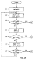
- the microprocessor 62 acting as a main processing unit executes a control program stored in the ROM 63. During the program execution, relevant data will be stored in the RAM 64. Referring to Figs. 4A, 4B, 4C and 4D, an exemplary operation of the microprocessor 62 will now be described in accordance with the specific decision logic of the present invention. Other decision logic may also be advantageouly and equally adopted and stored within the ROM 63. Further, some parts of the following sequences may be changed or eliminated for efficiency and for application in specific purposes.
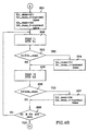
- the main sequence, shown in Fig. 4A, is repeated as long as the microwave oven power is on.
- the sequence will be started from Block 101 after the power on or the resetting of the microprocessor 62.
- Block 102 reads the two input signals currently held at the lines I 1 and I 3 of the I/O port 61 (shown in Fig. 2) into ti 1 and ti 3 stored in the RAM 64.
- ti 1 and ti 3 exceeds a predetermined value V 200
- the predetermined value V 200 stored in the ROM 63 corresponds to the least significant value from the lines I 1 and I 3 , which would indicate the door being closed.
- the value V 200 is determined empirically.
- Block 104 then reads the input signal held at the line I 5 of the I/O port 61 into ti 5 stored in the RAM 64.
- ti 5 is low to acknowledge that the door open switch has been pressed, the sequence will be diverted to the expected door open processing sequence shown in Fig. 4C, which will be explained later.
- Block 106 then reads the two input signals currently held at the lines I 2 and I 4 of the I/O port 61 into ti 2 and ti 4 stored in the RAM 64.
- ti 2 and ti 4 exceeds another predetermined value V 300 , the sequence will be diverted to the unexpected door open processing sequence shown in Fig. 4D, which will be explained later.
- the predetermined value V 300 stored in the ROM 63 corresponds to the least significant value from the lines I 2 and I 4 , which would indicate the door being opened.
- the value V 300 is determined through experiments. The main sequence from the block 102 will be repeated until the power off or the resetting of the microprocessor 62 happens.
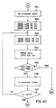
- Block 201 sets variables stored in the RAM 64. That is, Block 201 assigns the ti 1 and the ti 3 to ti 1 _max and ti 3 _max respectively and assings current time to ti 1 _max_t and ti 3 _max_t. Block 202 then reads again the input signal currently held at the line I 1 of the I/O port 61 into the ti 1 .
- Block 205 reads the input signal currently held at the line I 3 of the I/O port 61 into the ti 3 . If the ti 3 is greater than or equal to the ti 3 _max, then the ti 3 _max will be newly set to the ti 3 and current time will be written into the ti 3 _max_t at Block 207. Thereafter, the subsequence from Block 202 to Block 208 will be repeated until both the ti 1 and the ti 3 drop to zero.
- Block 209 determines whether all of the following three conditions are met: both the ti 1 _max and the ti 3 _max are greater than another predetermined value V 250 , the ti 1 _max is equal to the ti 3 _max within the predetermined permissable boundary E 200 ; and the ti 1 _max_t is equal to the ti 3 _max_t within another predetermined permissible boundary E 250 .
- the predetermined value V 250 stored in the ROM 63 corresponds to the least significant value from the lines I 1 and I 3 , which would indicate the door is completely closed.
- the predetermined value E 200 also stored in the ROM 63 is provided for compensating the errors which may come from the time interval between the readings of the line I 1 and the line I 3 , the differences in the characteristics of the A/D converters (shown in Fig. 2), etc.
- the predetermined value E 250 stored in the ROM 63 stands for similar purposes.
- the predetermined values V 250 , E 200 , E 250 should be set through experiments. If all of the three conditions are met, it can be recognized that the door is completely closed.
- Block 210 provides a high signal for each of the lines O 1 and O 3 of the I/O port 61 to magnetically latch the door until either an expected or an unexpected opening happens.
- Block 210 also provides another high signal at the line O 5 of the I/O port 61 to make it possible to connect the AC power to the loads of the microwave oven. In this state, pressing the start/stop switch will initiate/end the radiation of electromagnetic energy.
- Block 211 generates an appropriate display signal at the line O 6 of the I/O port 61 to tell the user that the door is not completely closed and provides a high signal for the line O 7 of the I/O port 61 to make a buzzer sound.
- the display means 90 and the alarm means 95 (shown in fig. 2) will be activated until the user fixes the fault and resets the microprocessor 62 by using the reset terminal 66 (shown in Fig. 2).
- return to the main sequence is performed.
- the expected door open processing sequence shown in Fig. 4C, is executed when the door open switch has been pressed as stated above.
- Block 301 assigns current time to a variable t 0 stored in the RAM 64. Then, at Block 302, the high signal which was provided for each of the lines O 1 and O 3 to magnetically latch the door becomes low. Further, the high signal which was provided at the line O 5 of the I/O port 61 falls low to cut out the AC power from the loads of the microwave oven. Block 303 then provides a high signal for each of the lines O 2 and O 4 of the I/O port 61 to introduce repelling forces between the permanent magnets 20,20' and the electromagnets 30,30'. Block 304 then reads the two input signals currently held at the lines I 2 and I 4 of the I/O port 61 into the ti 2 and the ti 4 . When each of the ti 2 and the ti 4 exceeds the predetermined value V 300 , Block 308 will be entered.
- the predetermined value V 300 together with the meaning thereof has already been mentioned in the context of the main sequence.
- Block 306 assigns current time to a variable t 1 stored in the RAM 64 and then, Block 307 determines whether (t 1 -t 0 ) is above a time limit T 1 stored in the ROM 63: in other words, whether the door does not begin to open until the predetermined time limit T 1 elapsed. If the condition is not met, the subsequence from Block 303 will be repeated. If the condition is met, Block 313 will be entered, which will be described hereinafter.
- Block 308 the high signal which was provided for each of the lines O 2 and O 4 to introduce repelling forces between the permanent magnets 20,20' and the electromagnets 30,30' falls low.
- Block 309 then again reads the two input signals currently held at the lines I 2 and I 4 of the I/O port 61 into the ti 2 and the ti 4 . Thereafter, Block 310 assigns current time to a variable t 2 stored in the RAM 64. Block 311 then determines whether both the ti 2 and the ti 4 are zero. If the condition does not hold, the subsequence from the block 309 will be repeated.
- Block 312 determines if (t 2 -t 0 )(which corresponds to the period that the door is being opened) is above another predetermined time limit T 2 stored in the ROM 63.
- the time limit T 2 must be long enough that it can be recognized that the door has been successfully opened without interruption. If the (t 2 -t 0 ) is above the time limit, recognizing that the door is opened successfully, the sequence will be returned to the main sequence at Block 314.
- Block 313 will generate an appropriate display signal at the line O 6 of the I/O port 61 to tell the user that the door is not completely opened, and provide a high signal at the line O 7 of the I/O port 61 to make a buzzer sound.
- the display means 90 and the alarm means 95 will be activated until the user fixes the fault and resets the microprocessor 62.
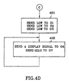
- Fig. 4D shows the unexpected door open processing sequence. The sequence will be entered when the door is being opened unexpectedly as stated above.
- Block 401 the high signal which was provided for each of the lines O 1 and O 3 of the I/O port 61 to magnetically latch the door falls low. Further, the high signal which was provided at the line O 5 of the I/O port 61 falls low to cut out the AC power from the loads of the microwave oven.
- Block 402 generates an appropriate display signal at the line O 6 of the I/O port 61 to tell the user that the door is being opened unexpectedly, and provides a high signal at the line O 7 of the I/O port 61 to make a buzzer sound.
- the display means 90 and the alarm means 95 will be activated until the user fixes the fault and resets the microprocessor 62.
Landscapes
- Physics & Mathematics (AREA)
- Engineering & Computer Science (AREA)
- Electromagnetism (AREA)
- General Physics & Mathematics (AREA)
- Chemical & Material Sciences (AREA)
- Combustion & Propulsion (AREA)
- Mechanical Engineering (AREA)
- General Engineering & Computer Science (AREA)
- Electric Ovens (AREA)
- Control Of High-Frequency Heating Circuits (AREA)
Description
- The present invention relates to a microwave oven; and is more particularly concerned with a microwave oven door control device capable of accurately detecting a faulty state of the door and facilitating the latching and the opening operations of the door and starts from DE-A-38 40 650.
- Generally, a microwave oven has a door to provide a user access to the interior(cavity) of the microwave oven. The door also prevents the leakage of electromagnetic radiation during the operation of the microwave oven.
- A typical present day microwave oven employs hook-type door latches and slots on an oven wall in order to keep its door closed once the door is in the closed position. The door latches are usually secured in the locked position during the heating operation by means of mechanical locking structure or electrically actuated locking structure employing a solenoid. The microwave oven also has a mechanical or optical switch(or switches) which tells a closed state from an open state. The microwave oven can initiate and continue the heating operation only when the door is in the closed position. Two such arrangements are disclosed in U.S. Patent No. 3,733,456 issued to Louis W. Blackburn and Japanese Patent Laid-open Publication No. 60-33207.
- Furthermore, DE-A-3 840 650 describes a microwave oven according to the preamble of
new claim 1. This microwave oven comprises electromagnetic means for detecting the state of the door, i.e. if the door is closed or open. Thereby, a permanent magnet is provided at the microwave oven door and disposed so as to get into contact with a corresponding electromagnet installed at the housing of the microwave oven. When the door is closed or opened currents are induced into the electromagnet. The induced currents are used as information about the opened or closed state of the door. However, this technique has no effect on the physical forces necessary to close or open the door. Furthermore, the known microwave oven uses a complicated technique based on high frequency a.c. signals applied to transmitter and receiver coils. - A problem with such arrangements is that it is difficult and cumbersome to equip a microwave oven door with the door latches and it is also cumbersome to form the slots on a oven wall.
- Another problem with such arrangements is that the door assembly can easily be worn away due to the physical forces used to open and close the door.
- It is, therefore, an object of the present invention to provide a microwave oven with a novel oven door latching/ opening means which uses magnetic materials(e.g., ferromagnetics or permanent magnets) and electromagnets in place of hook-type door latches and slots on a oven wall.
- It is also an object of the present invention to provide a microwave oven with means for detecting the state of the door which utilizes the existing magnetic materials and electromagnets rather than employing a seperate detecting means.
- Another object is to provide such door latching/opening means which can be fabricated readily and relatively economically, and which has a durable operability.
- These objects are achieved by the features of
claim 1 and those of the dependent claims 2 to 6. - Accordingly, the present invention provides a microwave oven with an automatic door control device, which comprises: an enclosure having therein a heating chamber adapted to receive an object to be heated; a door mounted at an opening of the heating chamber; at least one magnetic material provided at one side of the door; at least one electromagnet provided on the enclosure and adapted to contact with the magnetic material; at least one door state detecting means connected with the electromagnet for generating a first signal based on electromotive forces, said electromotive forces being generated in the electromagnet when the door is being closed or opened; a door open switch means for generating a second signal, said second signal being generated upon pressing a door open switch; a processing means for generating a control signal in response to the first signal and the second signal; at least one door latching and opening means connected with the electromagnet for latching and opening the door in response to the control signal, said door being latched while an electric current is applied to said electromagnet in one direction and opened when another current is applied to the electromagnet in another direction; a microwave energy generator adapted to radiate energy within the enclosure; and a load driving power switching means for operating the generator in response to the control signal.
- The above and other objects and features of the present invention will become apparent from the following descriptions given in conjunction with the accompanying drawings, in which:
- Fig. 1 shows a perspective view of a microwave oven emboding the present invention;
- Fig. 2 depicts a control circuit diagram of the embodiment;
- Figs. 3A and 3B describes the respective directions of the currents induced in the coil of an electromagnet when a permanent magnet moves horizontally to and from the electromagnet; and
- Figs. 4A, 4B, 4C and 4D represent flowcharts which illustrate the operation of the processing means shown in Fig. 2.
-
- The construction of the present invention is described hereinafter referring to the drawings, which show the preferred embodiments of the present invention.
- In Fig. 1, the
enclosure case 10 comprises aheating chamber 11 wherein an object to be heated such as food is to be placed. Theheating chamber 11 has adoor 12 mounted by means of, e.g., hinges 13 at one e.g., left, side portion of theenclosure case 10. A control panel 14 on which a display unit 5 and control switches SW(e.g., a start/stop switch, a door open switch, etc.) may be located is provided at the other, e.g., right, side portion of theenclosure case 10. In addition, magnetic materials (e.g., ferromagnetics or permanent magnets) 20,20' are provided at one side, for example, at the right side portion of thedoor 12 and disposed so as to contact with thecorresponding electromagnets 30,30' installed in theenclosure case 10. - Turning now to the sequence of heating operation with reference to Fig. 1, at first, the user places an object to be heated into the
heating chamber 11 and then, closes theoven door 12. As the door is being closed, thepermanent magnets 20,20' gets closer to theelectromagnets 30,30' and as a result, currents are induced in the coils of theelectromagnets 30,30'. The induced currents are used by a control circuit to detect the two closing stages of the door(i.e., when the door is being closed; and when the door is completely closed). - With the door completely closed, the control circuit will apply currents in one direction to the coils of the
electromagnets 30,30' to introduce attracting forces between thepermanent magnets 20,20' and theelectromagnets 30,30' until either an expected(i.e., opening by pressing the door open switch) or an unexpected (i.e., opening by physical forces) opening of the door happens. Accordingly, the door can be magnetically latched once the door has been closed. - In this state, pressing the start/stop switch will initiate/end the radiation of microwaves within the
heating chamber 11. - An energy generator for the generation of microwaves, under the control of the control circuit, can radiate microwaves only while the door is in the properly closed state. That is, when the door is not completely closed, the energy generator will not be initiated even if the start/stop switch is pressed. And when either the expected or the unexpected opening happens, the energy generator once initiated will stop its microwave radiating operation.
- When the user presses the door open switch to remove the heated object from the
heating chamber 11, currents will be applied for a period in a reverse direction to the coils of theelectromagnets 30,30' to introduce strong repelling forces between thepermanent magnets 20,20' and theelectromagnets 30,30'. Consequently, the oven door can be opened without any intervening physical forces. - When the door is being opened expectedly or unexpectedly, the
permanent magnets 20,20' will gradually become distanced from theelectromagnets 30,30'; and, as a result, currents are induced in the coils of theelectromagnets 30,30' in the opposite direction to the previous one. The induced currents are used by the control circuit to detect the two opening stages of the door (i.e., when the door is being opened; and when the door is completely opened). - Further, the control circuit will generate a buzzer sound with an appropriate indication on the display unit 5 when: the door is not completely closed; the door is being opened unexpectedly; or the door is not completely opened upon the pressing of the door open switch .
- Fig. 2 shows the control circuit diagram of an exemplary embodiment of the present invention.
- In Fig. 2, each of the
electromagnets 30,30' is connected with the door state detecting means 40 or 40' and the door latching/opening means 50 or 50'. The door state detecting means 40(40')is also connected to the lines I1(I3) and I2(I4) of the I/O port 61 of the processing means 60. And the door latching/opening means 50(50') is also connected to the lines O1(O2) and O2(O4) of the I/O port 61. - The door state detecting means 40 preferably comprises a diode D1, a resistor R1, a condenser C1 and an A/
D converter 41 in one part and a diode D2, resistors R2,R3,R4, a condenser C2, an amplifier OP1, and an A/D converter 42 in the other part as shown in Fig. 2. Referring to Figs. 2 and 3, the operations of the door state detecting means 40 will now be fully described. In the first place, we will assume the oven door is being closed. As the door is being closed, thepermament magnet 20 with the pole directions shown in Figs. 2 and 3 approaches theelectromagnet 30; and, as a result, electric current is induced in the coil of theelectromagnet 30 in the direction shown in Fig. 3A. The induced current will flow from the coil to the A/D converter 41 through the diode D1, the resistor R1 and the condenser C1. Hence, the voltage across the condenser C1 will be applied to the A/D converter 41 as an input votage thereof. Further, as thepermanent magnet 20 approaches theelectromagnet 30, the induced emf(electromotive force) will gradually be increased and so will the voltage across the condenser C1. Accordingly, the voltage has its peak value at the point of time just before thepermanent magnet 20 contacts with theelectromagnet 30. The A/D converter 41 then converts the time-varying analog input voltage signal to the appropriate bits (for example, 8 bits) of a digital signal. The resulting bits of digital signal will be sent in parallel through the line I1 to the processing means 60 which will be described later. - Secondly, we will assume the door is being opened expectedly or unexpectedly. As the door is being opened, the
permanent magnet 20 becomes more distant from theelectromagnet 30; and, as a result, electric current is induced in the coil of theelectromagnet 30 in the direction shown in Fig. 3B. The induced negative current is applied through the diode D2 and the resistor R2 to the input terminal of the inverting voltage amplifier comprising the amplifier OP1 and the resistor R3. Hence, the inverted positive voltage across the condenser C2 will be applied to the A/D converter 42 as an input voltage thereof. Meanwhile, as thepermanent magnet 20 moves away from theelectromagnet 30, the absolute value of the induced emf will gradually be decreased until zero and so will the voltage across the condenser C2. Accordingly, the voltage has its peak value at the point of time when thepermanent magnet 20 has just departed from theelectromagnet 30. The A/D converter 42 then converts the time-varying analog input voltage signal to the appropriate bits of a digital signal. The resulting bits of digital signal will also be sent in parallel through the line I2 to the processing means 60. - In Fig. 2, the door latching/opening means 50 preferably comprises two transistors TR1, TR2. The base of the TR1 is connected with the line O1 of the I/
O port 61 while its emitter is connected with the coil of theelectromagnet 30. Accordingly, when an output signal at the line O1 is high, the transistor TR1 will be turned on. As a result, electric current will flow from a voltage source V to the ground through the coil of theelectromagnet 30, which will introduce attracting forces between thepermanent magnet 20 and theelectromagnet 30. Therefore, the oven door can be magnetically latched by the output signal from the processing means 60 once the door has been closed. - On the other hand, the base of the TR2 is connected with the line O2 of the I/
O port 61 while its collector is connected with the coil of theelectromagnet 30. Accordingly, when the output signal at the line O2 is high, the transistor TR2 will be turned on. As a result, electric current will flow from the ground to a voltage source -V through the coil of theelectromagnet 30, which will introduce repelling forces between thepermanent magnet 20 and theelectromagnet 30. Therefore, the oven door can be opened by the output signal from the processing means 60 upon the pressing of the door open switch. - A load driving power switching means 70 is shown on the right side to the I/
O port 61. The switching means 70 comprises two resistors, a relay and a transistor whose base is connected to the line O5 of the I/O port 61. Accordingly, as far as the output signal at the line O5 is held high, the transistor becomes turned on and the relay makes its contact. Thereby, the switching means 70 controllably connects an AC source (not shown) to the loads(e.g., microwave generator, fan, motor, etc. also not shown) of the microwave oven. That is to say, in the event of a faulty situation i.e., when the oven door is not completely closed or when the door is opened expectedly or unexpectedly, the output signal at the line O5 becomes low, which will disconnect the AC source from the loads. - A door open switch means 80 is also shown in Fig. 2 as being connected to the line I5 of the I/
O port 61. The door open switch means comprises a voltage divider having two resistors and the door open switch. Upon the appropriate pressing of the switch, a low signal will be applied through the line I5 to the processing means 60. - A display means 90 and an alarm means 95 are also connected to the I/
O port 61. The display means is shown as being connected to the line O6. It comprises mainly seven-segment LED units. The alarm means is connected to the line O7. It comprises two resistors, a transistor and a buzzer. These means will be activated upon the occurrence of any of the following faulty situations: when the door is not completely closed, the door is not completely opened upon the pressing of the door open switch or the door is being opened unexpectedly. - Further, the processing means 60 shown in Fig. 2 preferably comprises the I/
O port 61, amicroprocessor 62 with a reset terminal 66, a ROM 63, aRAM 64 and asystem bus 65. Although not specifically shown, the system bus may include a data bus, an address bus and a control bus. The input and the output signals of the I/O port 61, which are mentioned hereinabove, are processed by the processing means 60. - The
microprocessor 62 acting as a main processing unit executes a control program stored in the ROM 63. During the program execution, relevant data will be stored in theRAM 64. Referring to Figs. 4A, 4B, 4C and 4D, an exemplary operation of themicroprocessor 62 will now be described in accordance with the specific decision logic of the present invention. Other decision logic may also be advantageouly and equally adopted and stored within the ROM 63. Further, some parts of the following sequences may be changed or eliminated for efficiency and for application in specific purposes. - The main sequence, shown in Fig. 4A, is repeated as long as the microwave oven power is on. The sequence will be started from Block 101 after the power on or the resetting of the
microprocessor 62. After an initialization,Block 102 reads the two input signals currently held at the lines I1 and I3 of the I/O port 61 (shown in Fig. 2) into ti1 and ti3 stored in theRAM 64. When each of ti1 and ti3 exceeds a predetermined value V200, the sequence will be diverted to the door close processing sequence shown in Fig. 4B, which will be explained later. The predetermined value V200 stored in the ROM 63 corresponds to the least significant value from the lines I1 and I3, which would indicate the door being closed. The value V200 is determined empirically. -
Block 104 then reads the input signal held at the line I5 of the I/O port 61 into ti5 stored in theRAM 64. When the ti5 is low to acknowledge that the door open switch has been pressed, the sequence will be diverted to the expected door open processing sequence shown in Fig. 4C, which will be explained later. -
Block 106 then reads the two input signals currently held at the lines I2 and I4 of the I/O port 61 into ti2 and ti4 stored in theRAM 64. When each of ti2 and ti4 exceeds another predetermined value V300, the sequence will be diverted to the unexpected door open processing sequence shown in Fig. 4D, which will be explained later. The predetermined value V300 stored in the ROM 63 corresponds to the least significant value from the lines I2 and I4, which would indicate the door being opened. The value V300 is determined through experiments. The main sequence from theblock 102 will be repeated until the power off or the resetting of themicroprocessor 62 happens. - The door close processing sequence, shown in Fig. 4B, is executed when the door is being closed as stated above.
Block 201 sets variables stored in theRAM 64. That is,Block 201 assigns the ti1 and the ti3 to ti1_max and ti3_max respectively and assings current time to ti1_max_t and ti3_max_t.Block 202 then reads again the input signal currently held at the line I1 of the I/O port 61 into the ti1. If the ti1 is greater than or equal to the ti1_max previously stored, then the ti1_max will be newly set to the ti1 and current time will be written into the ti1_max_t atBlock 204. Accordingly, the ti1_max will be always set to the maximum input signal from the line I1 upto that point.Block 205 reads the input signal currently held at the line I3 of the I/O port 61 into the ti3. If the ti3 is greater than or equal to the ti3_max, then the ti3_max will be newly set to the ti3 and current time will be written into the ti3_max_t atBlock 207. Thereafter, the subsequence fromBlock 202 to Block 208 will be repeated until both the ti1 and the ti3 drop to zero. -
Block 209 determines whether all of the following three conditions are met: both the ti1_max and the ti3_max are greater than another predetermined value V250, the ti1_max is equal to the ti3_max within the predetermined permissable boundary E200; and the ti1_max_t is equal to the ti3_max_t within another predetermined permissible boundary E250. The predetermined value V250 stored in the ROM 63 corresponds to the least significant value from the lines I1 and I3, which would indicate the door is completely closed. The predetermined value E200 also stored in the ROM 63 is provided for compensating the errors which may come from the time interval between the readings of the line I1 and the line I3, the differences in the characteristics of the A/D converters (shown in Fig. 2), etc. The predetermined value E250 stored in the ROM 63 stands for similar purposes. The predetermined values V250, E200, E250 should be set through experiments. If all of the three conditions are met, it can be recognized that the door is completely closed. Hence,Block 210 provides a high signal for each of the lines O1 and O3 of the I/O port 61 to magnetically latch the door until either an expected or an unexpected opening happens. Block 210 also provides another high signal at the line O5 of the I/O port 61 to make it possible to connect the AC power to the loads of the microwave oven. In this state, pressing the start/stop switch will initiate/end the radiation of electromagnetic energy. - On the other hand, if any of the three conditions is not met, it can be recognized that the door is not completely closed because, for example, some alien substance has intervened between the
permanent magnets 20,20' (shown in Fig. 2) and theelectromagnets 30,30' (also shown in Fig. 2). Therefore,Block 211 generates an appropriate display signal at the line O6 of the I/O port 61 to tell the user that the door is not completely closed and provides a high signal for the line O7 of the I/O port 61 to make a buzzer sound. The display means 90 and the alarm means 95 (shown in fig. 2) will be activated until the user fixes the fault and resets themicroprocessor 62 by using the reset terminal 66 (shown in Fig. 2). Finally, atBlock 212, return to the main sequence is performed. - The expected door open processing sequence, shown in Fig. 4C, is executed when the door open switch has been pressed as stated above.
- At first,
Block 301 assigns current time to a variable t0 stored in theRAM 64. Then, atBlock 302, the high signal which was provided for each of the lines O1 and O3 to magnetically latch the door becomes low. Further, the high signal which was provided at the line O5 of the I/O port 61 falls low to cut out the AC power from the loads of the microwave oven.Block 303 then provides a high signal for each of the lines O2 and O4 of the I/O port 61 to introduce repelling forces between thepermanent magnets 20,20' and theelectromagnets 30,30'.Block 304 then reads the two input signals currently held at the lines I2 and I4 of the I/O port 61 into the ti2 and the ti4. When each of the ti2 and the ti4 exceeds the predetermined value V300,Block 308 will be entered. The predetermined value V300 together with the meaning thereof has already been mentioned in the context of the main sequence. - If the condition is not met, the time limit must be checked at
Blocks Block 306 assigns current time to a variable t1 stored in theRAM 64 and then,Block 307 determines whether (t1-t0) is above a time limit T1 stored in the ROM 63: in other words, whether the door does not begin to open until the predetermined time limit T1 elapsed. If the condition is not met, the subsequence fromBlock 303 will be repeated. If the condition is met,Block 313 will be entered, which will be described hereinafter. - At
Block 308, the high signal which was provided for each of the lines O2 and O4 to introduce repelling forces between thepermanent magnets 20,20' and theelectromagnets 30,30' falls low.Block 309 then again reads the two input signals currently held at the lines I2 and I4 of the I/O port 61 into the ti2 and the ti4. Thereafter,Block 310 assigns current time to a variable t2 stored in theRAM 64.Block 311 then determines whether both the ti2 and the ti4 are zero. If the condition does not hold, the subsequence from theblock 309 will be repeated. - On the other hand, if the condition does hold,
Block 312 will be entered.Block 312 determines if (t2-t0)(which corresponds to the period that the door is being opened) is above another predetermined time limit T2 stored in the ROM 63. The time limit T2 must be long enough that it can be recognized that the door has been successfully opened without interruption. If the (t2-t0) is above the time limit, recognizing that the door is opened successfully, the sequence will be returned to the main sequence atBlock 314. - However, if it is not true, assuming that some interruption has been made during the period, the sequence will execute
Block 313.Block 313 will generate an appropriate display signal at the line O6 of the I/O port 61 to tell the user that the door is not completely opened, and provide a high signal at the line O7 of the I/O port 61 to make a buzzer sound. The display means 90 and the alarm means 95 will be activated until the user fixes the fault and resets themicroprocessor 62. - Fig. 4D shows the unexpected door open processing sequence. The sequence will be entered when the door is being opened unexpectedly as stated above.
- At
Block 401, the high signal which was provided for each of the lines O1 and O3 of the I/O port 61 to magnetically latch the door falls low. Further, the high signal which was provided at the line O5 of the I/O port 61 falls low to cut out the AC power from the loads of the microwave oven.Block 402 generates an appropriate display signal at the line O6 of the I/O port 61 to tell the user that the door is being opened unexpectedly, and provides a high signal at the line O7 of the I/O port 61 to make a buzzer sound. The display means 90 and the alarm means 95 will be activated until the user fixes the fault and resets themicroprocessor 62. - The above-described arrangements are, of course, merely illustrative of the application of the principles of the invention. Other arrangements may be devised by those skilled in the art without departing from the spirit or scope of the invention. For example, it will be appreciated that it may be advantageous in certain application to employ more than two pairs of magnetic material and electromagnet with a corresponding number of door state detecting means and door latching/opening means. Also, the processing means can advantageously be replaced by a hard-wired logic circuit.
- Again, it is to be understood that the invention is not to be limited to the disclosed embodiments; but, on the contrary, it is intended to cover various modifications and equivalent arrangements included within the spirit and scope of the appended claims.
Claims (6)
- A microwave oven comprising:characterized byan enclosure (10) having therein a heating chamber (11) adapted to receive an object to be heated;a door (12) mounted at an opening of the heating chamber (11);at least one magnetic material (20; 20') provided at one side of the door (12);at least one electromagnet (30; 30) provided on the enclosure (10) and adapted to contact with the magnetic material (20; 20');a door open switch means (80) for generating a first signal, said signal being generated upon pressing a door open switch (SW);a processing means (60) for generating a control signal in response to said signal; andat least one door latching and/or opening means (50; 50') connected with the electromagnet (30; 30) for latching and/or opening the door (12) in response to the control signal, said door (12) being latched when an electric current is applied to said electromagnet (30; 30) in one direction and opened when another current is applied to the electromagnet (30; 30) in a reverse direction.
- The microwave oven as set forth in claim 1 further comprising:at least one door state detecting means (40; 40) connected with the electromagnet (30; 30) for generating a second signal based on electromotive forces, said electromotive forces being generated in the electromagnet (30; 30) when the door (12) is being closed or opened, wherein the processing means (60) generate a control signal in response the the first and second signals; anda load driving power switching means (70) for operating a microwave energy generator in response to the control signal, said generator being adapted to radiate energy within the enclosure (10).
- The microwave oven as set forth in claim 2 further comprising:a second processing means (60) for generating a display signal in response to the first and second signals; anda display means (90) for displaying a faulty symbol in response to said display signal, said symbol being displayed when a corresponding faulty state of the door (12) occurs.
- The microwave oven as set forth in claim 2 further comprising:a second processing means (60) for generating a second control signal in response to the first and second signals; andan alarm means (95) for generating an alarm sound in response to the second signal, said alarm sound being generated when a faulty state of the door (12) occurs.
- The microwave oven as set forth in claims 1 or 2 wherein said processing means (60) comprises at least one input/output port (61), one microprocessor (62) and one memory (63; 64).
- The microwave oven as set forth in claims 1 or 2 wherein said magnetic material (20; 20') is a permanent magnet or a ferromagnetic.
Applications Claiming Priority (2)
| Application Number | Priority Date | Filing Date | Title |
|---|---|---|---|
| KR2563691 | 1991-12-31 | ||
| KR1019910025636A KR940007232B1 (en) | 1991-12-31 | 1991-12-31 | Microwave Oven Door Opener |
Publications (3)
| Publication Number | Publication Date |
|---|---|
| EP0550897A2 EP0550897A2 (en) | 1993-07-14 |
| EP0550897A3 EP0550897A3 (en) | 1993-09-29 |
| EP0550897B1 true EP0550897B1 (en) | 1999-10-27 |
Family
ID=19327126
Family Applications (1)
| Application Number | Title | Priority Date | Filing Date |
|---|---|---|---|
| EP92122034A Expired - Lifetime EP0550897B1 (en) | 1991-12-31 | 1992-12-28 | Microwave oven door control device |
Country Status (5)
| Country | Link |
|---|---|
| US (1) | US5293020A (en) |
| EP (1) | EP0550897B1 (en) |
| JP (1) | JPH086930B2 (en) |
| KR (1) | KR940007232B1 (en) |
| DE (1) | DE69230216D1 (en) |
Families Citing this family (34)
| Publication number | Priority date | Publication date | Assignee | Title |
|---|---|---|---|---|
| JP3321845B2 (en) * | 1992-09-30 | 2002-09-09 | 松下電器産業株式会社 | oven |
| ES1033220Y (en) * | 1996-01-30 | 1997-01-01 | Garcia Vicente Gil | DEVICE FOR THE CLOSING AND AUTOMATIC OPENING OF THE COVER OF A KITCHEN INSTRUMENT, ESPECIALLY GRILLS, PLATES AND SIMILAR. |
| KR100281800B1 (en) * | 1996-06-27 | 2001-02-15 | 윤종용 | Microwave power cutoff device |
| US5955795A (en) * | 1996-10-28 | 1999-09-21 | Beer; David W. | Apparatus for enclosing appliances |
| GB2321836B (en) * | 1997-01-30 | 2000-09-06 | Stoves Plc | Cooking ovens |
| ATE318359T1 (en) | 1998-08-19 | 2006-03-15 | Fisher & Paykel Appliances Ltd | DOOR OPENING AND CLOSING SYSTEM |
| US6313445B1 (en) | 2001-01-03 | 2001-11-06 | Hp Intellectual Corp. | Control for an electrical kitchen appliance with power interruption off feature |
| GB2389145B (en) * | 2002-05-31 | 2007-03-21 | James Clark | Letter box lock |
| DE102004007235C5 (en) * | 2004-02-13 | 2016-01-28 | Convotherm Elektrogeräte GmbH | Commercial cooking appliance |
| US20050236408A1 (en) * | 2004-04-08 | 2005-10-27 | Maytag Corporation | Door position sensing system for cooking appliance including combination heating system |
| US7225804B2 (en) * | 2004-11-12 | 2007-06-05 | Bsh Home Appliances Corporation | Motor driven oven door latch |
| US7654590B2 (en) * | 2005-01-04 | 2010-02-02 | Illinois Tool Works, Inc. | Magnetic appliance latch |
| US7009147B1 (en) | 2005-01-12 | 2006-03-07 | Maytag Corporation | Operational modes for a cooking appliance employing combination cooking technology |
| KR100744509B1 (en) * | 2005-12-22 | 2007-08-01 | 엘지전자 주식회사 | Heater control device of thermal drawer and method |
| WO2007122265A1 (en) * | 2006-04-26 | 2007-11-01 | Quantifoil Instruments Gmbh | A sample handling device for and a method of handling a sample |
| KR101085901B1 (en) * | 2006-09-28 | 2011-11-23 | 삼성전자주식회사 | Cooker |
| KR100821751B1 (en) * | 2006-11-08 | 2008-04-14 | 엘지전자 주식회사 | Microwave ovens and switchgear |
| US8231151B2 (en) * | 2009-05-07 | 2012-07-31 | Simplexgrinnell Lp | Magnetic releasing and securing device |
| DE102010043537A1 (en) * | 2010-11-08 | 2012-05-10 | BSH Bosch und Siemens Hausgeräte GmbH | household appliance |
| US20130069512A1 (en) * | 2011-09-19 | 2013-03-21 | General Electric Company | Actuated door opening mechanism for microwave and speedcooking products |
| US9290972B2 (en) * | 2013-10-15 | 2016-03-22 | General Electric Company | Latch assembly |
| US9347247B2 (en) * | 2013-10-30 | 2016-05-24 | General Electric Company | Latch assembly |
| KR102208569B1 (en) * | 2014-07-07 | 2021-01-28 | 삼성전자주식회사 | Microwave oven |
| US20160116171A1 (en) * | 2014-10-22 | 2016-04-28 | General Electric Company | Oven airflow control |
| CN107448080A (en) * | 2016-05-30 | 2017-12-08 | 北京小米移动软件有限公司 | The control method and device of frame members, frame members applied to micro-wave oven |
| DE102016213136A1 (en) * | 2016-07-19 | 2018-02-08 | BSH Hausgeräte GmbH | Door monitoring circuit for a household appliance |
| WO2018038702A1 (en) | 2016-08-22 | 2018-03-01 | Whirlpool Corporation | Microwave oven having generator power supply |
| EP3563627B1 (en) | 2016-12-27 | 2022-04-27 | Whirlpool Corporation | Low cost solid state rf generation system for electromagnetic cooking |
| AU2018295558B2 (en) | 2017-07-06 | 2024-05-02 | Breville Pty Limited | A retractable door for an oven |
| US10834789B2 (en) | 2017-12-19 | 2020-11-10 | Whirlpool Corporation | Electronic door opening system |
| JP7153591B2 (en) * | 2019-03-22 | 2022-10-14 | シャープ株式会社 | heating device |
| CN113932259A (en) * | 2020-06-29 | 2022-01-14 | 广东美的厨房电器制造有限公司 | Microwave heating device |
| CN113647840A (en) * | 2021-08-02 | 2021-11-16 | 海信家电集团股份有限公司 | Baking equipment and control method thereof |
| CN115429124A (en) * | 2022-09-23 | 2022-12-06 | 珠海格力电器股份有限公司 | Cooking appliance and door opening control method thereof |
Family Cites Families (13)
| Publication number | Priority date | Publication date | Assignee | Title |
|---|---|---|---|---|
| GB980872A (en) * | 1961-10-27 | 1965-01-20 | Radyne Ltd | Improvements in or relating to radio frequency heating apparatus |
| US3627959A (en) * | 1970-03-19 | 1971-12-14 | Sage Laboratories | Magnetic latching and switching |
| US3784776A (en) * | 1970-04-20 | 1974-01-08 | Tokyo Shibaura Electric Co | Electromagnetic locking mechanism for a microwave oven |
| CA1137174A (en) * | 1978-12-19 | 1982-12-07 | Keiichiro Doi | Error alarm system in a microwave oven |
| JPS5743135A (en) * | 1980-08-29 | 1982-03-11 | Matsushita Electric Ind Co Ltd | High frequency heating device |
| JPS57129329A (en) * | 1981-02-02 | 1982-08-11 | Matsushita Electric Ind Co Ltd | High-frequency heating device |
| DE3206606C2 (en) * | 1982-02-24 | 1985-04-25 | Bosch-Siemens Hausgeräte GmbH, 7000 Stuttgart | Locking device for the door of an oven |
| DE3236290C2 (en) * | 1982-09-30 | 1985-08-08 | Bosch-Siemens Hausgeräte GmbH, 7000 Stuttgart | Device for monitoring the closed status of doors on microwave ovens |
| JPS6033207A (en) * | 1983-07-28 | 1985-02-20 | Denki Kagaku Kogyo Kk | Carbon black for surface heater |
| AU596039B2 (en) * | 1988-05-20 | 1990-04-12 | Kabushiki Kaisha Toshiba | Cooker |
| FR2639096B1 (en) * | 1988-11-17 | 1991-01-04 | Bourgeois Ste Coop Production | CLOSURE FOR OVEN |
| DE3840650A1 (en) * | 1988-12-02 | 1990-06-07 | Vogt Electronic Ag | Electronic door security lock for microwave appliances |
| DE3915541C2 (en) * | 1989-05-12 | 1994-02-03 | Vogt Electronic Ag | Arrangement for the electronic door monitoring of a microwave oven |
-
1991
- 1991-12-31 KR KR1019910025636A patent/KR940007232B1/en not_active Expired - Fee Related
-
1992
- 1992-12-28 DE DE69230216T patent/DE69230216D1/en not_active Expired - Lifetime
- 1992-12-28 JP JP4348773A patent/JPH086930B2/en not_active Expired - Lifetime
- 1992-12-28 EP EP92122034A patent/EP0550897B1/en not_active Expired - Lifetime
- 1992-12-29 US US07/998,012 patent/US5293020A/en not_active Expired - Fee Related
Also Published As
| Publication number | Publication date |
|---|---|
| JPH086930B2 (en) | 1996-01-29 |
| DE69230216D1 (en) | 1999-12-02 |
| EP0550897A2 (en) | 1993-07-14 |
| KR940007232B1 (en) | 1994-08-10 |
| KR930013591A (en) | 1993-07-22 |
| EP0550897A3 (en) | 1993-09-29 |
| JPH05248641A (en) | 1993-09-24 |
| US5293020A (en) | 1994-03-08 |
Similar Documents
| Publication | Publication Date | Title |
|---|---|---|
| US5293020A (en) | Microwave oven door control device | |
| US6208044B1 (en) | Removable media ejection system | |
| US4904837A (en) | Powered microwave oven | |
| US4816726A (en) | Method of and arrangement for controlling and h-bridge electric motor | |
| CA2005530A1 (en) | Integrated electronically commutated motor and control circuit assembly | |
| US4533810A (en) | Start circuit for microwave oven | |
| EP1166601B1 (en) | Dc microwave oven having a driving circuit | |
| US4383156A (en) | Control circuit for controlling a magnetron of a microwave oven | |
| KR100399138B1 (en) | Microwave oven | |
| KR950005746B1 (en) | Automatic door control system for microwave oven | |
| GB2293057A (en) | Controller for a microwave oven | |
| EP3599327A1 (en) | Electric power system applicable to electric door openers | |
| JPH09284992A (en) | Overload protector fro lifter | |
| KR100953636B1 (en) | Inrush Current Prevention Circuit of Microwave Oven | |
| KR930011808B1 (en) | Relay circuit of microwave oven | |
| GB2298740A (en) | Reed switch assembly | |
| JPH02132330U (en) | ||
| US20020023921A1 (en) | Microwave oven in which rush current to high voltage transformer is suppressed | |
| KR100212046B1 (en) | Microwave Lock Device | |
| KR970002635Y1 (en) | Micro Door Lock | |
| JP4016729B2 (en) | High frequency heating device | |
| JPH04359692A (en) | Motor lock detection circuit | |
| MCGEOCH et al. | Magnetically insulated opening switch research(Final Report, Jun. 1984-Oct. 1986) | |
| JPH03236134A (en) | Electronic control type device | |
| JPH01299380A (en) | Device for interlocking valve |
Legal Events
| Date | Code | Title | Description |
|---|---|---|---|
| PUAI | Public reference made under article 153(3) epc to a published international application that has entered the european phase |
Free format text: ORIGINAL CODE: 0009012 |
|
| AK | Designated contracting states |
Kind code of ref document: A2 Designated state(s): DE FR GB NL |
|
| PUAL | Search report despatched |
Free format text: ORIGINAL CODE: 0009013 |
|
| AK | Designated contracting states |
Kind code of ref document: A3 Designated state(s): DE FR GB NL |
|
| 17P | Request for examination filed |
Effective date: 19940324 |
|
| 17Q | First examination report despatched |
Effective date: 19960112 |
|
| GRAG | Despatch of communication of intention to grant |
Free format text: ORIGINAL CODE: EPIDOS AGRA |
|
| GRAG | Despatch of communication of intention to grant |
Free format text: ORIGINAL CODE: EPIDOS AGRA |
|
| GRAH | Despatch of communication of intention to grant a patent |
Free format text: ORIGINAL CODE: EPIDOS IGRA |
|
| GRAH | Despatch of communication of intention to grant a patent |
Free format text: ORIGINAL CODE: EPIDOS IGRA |
|
| GRAA | (expected) grant |
Free format text: ORIGINAL CODE: 0009210 |
|
| AK | Designated contracting states |
Kind code of ref document: B1 Designated state(s): DE FR GB NL |
|
| PG25 | Lapsed in a contracting state [announced via postgrant information from national office to epo] |
Ref country code: NL Free format text: LAPSE BECAUSE OF FAILURE TO SUBMIT A TRANSLATION OF THE DESCRIPTION OR TO PAY THE FEE WITHIN THE PRESCRIBED TIME-LIMIT Effective date: 19991027 Ref country code: FR Free format text: LAPSE BECAUSE OF FAILURE TO SUBMIT A TRANSLATION OF THE DESCRIPTION OR TO PAY THE FEE WITHIN THE PRESCRIBED TIME-LIMIT Effective date: 19991027 |
|
| REF | Corresponds to: |
Ref document number: 69230216 Country of ref document: DE Date of ref document: 19991202 |
|
| PG25 | Lapsed in a contracting state [announced via postgrant information from national office to epo] |
Ref country code: DE Free format text: LAPSE BECAUSE OF FAILURE TO SUBMIT A TRANSLATION OF THE DESCRIPTION OR TO PAY THE FEE WITHIN THE PRESCRIBED TIME-LIMIT Effective date: 20000128 |
|
| EN | Fr: translation not filed | ||
| NLV1 | Nl: lapsed or annulled due to failure to fulfill the requirements of art. 29p and 29m of the patents act | ||
| PLBE | No opposition filed within time limit |
Free format text: ORIGINAL CODE: 0009261 |
|
| STAA | Information on the status of an ep patent application or granted ep patent |
Free format text: STATUS: NO OPPOSITION FILED WITHIN TIME LIMIT |
|
| 26N | No opposition filed | ||
| PGFP | Annual fee paid to national office [announced via postgrant information from national office to epo] |
Ref country code: GB Payment date: 20011227 Year of fee payment: 10 |
|
| REG | Reference to a national code |
Ref country code: GB Ref legal event code: IF02 |
|
| PG25 | Lapsed in a contracting state [announced via postgrant information from national office to epo] |
Ref country code: GB Free format text: LAPSE BECAUSE OF NON-PAYMENT OF DUE FEES Effective date: 20021228 |
|
| GBPC | Gb: european patent ceased through non-payment of renewal fee |
Effective date: 20021228 |