EP0550842B1 - Adjustable orthotic - Google Patents
Adjustable orthotic Download PDFInfo
- Publication number
- EP0550842B1 EP0550842B1 EP92121017A EP92121017A EP0550842B1 EP 0550842 B1 EP0550842 B1 EP 0550842B1 EP 92121017 A EP92121017 A EP 92121017A EP 92121017 A EP92121017 A EP 92121017A EP 0550842 B1 EP0550842 B1 EP 0550842B1
- Authority
- EP
- European Patent Office
- Prior art keywords
- attachment means
- wedge
- orthotic
- orthopedic device
- sole
- Prior art date
- Legal status (The legal status is an assumption and is not a legal conclusion. Google has not performed a legal analysis and makes no representation as to the accuracy of the status listed.)
- Expired - Lifetime
Links
- 230000000399 orthopedic effect Effects 0.000 claims abstract description 17
- 210000004744 fore-foot Anatomy 0.000 claims abstract description 15
- 230000013011 mating Effects 0.000 claims abstract description 8
- 241001227561 Valgus Species 0.000 claims abstract description 6
- 241000469816 Varus Species 0.000 claims abstract description 6
- 210000002683 foot Anatomy 0.000 claims description 39
- -1 polyethylene terephthalate Polymers 0.000 claims description 4
- 229920000139 polyethylene terephthalate Polymers 0.000 claims description 4
- 239000005020 polyethylene terephthalate Substances 0.000 claims description 4
- 239000003086 colorant Substances 0.000 claims description 3
- 238000004513 sizing Methods 0.000 claims description 3
- 239000004677 Nylon Substances 0.000 claims description 2
- 229920001778 nylon Polymers 0.000 claims description 2
- 238000000034 method Methods 0.000 description 12
- 210000000474 heel Anatomy 0.000 description 11
- 239000000463 material Substances 0.000 description 10
- 210000003371 toe Anatomy 0.000 description 9
- 238000013459 approach Methods 0.000 description 5
- 238000005266 casting Methods 0.000 description 3
- 210000002414 leg Anatomy 0.000 description 3
- 210000003141 lower extremity Anatomy 0.000 description 3
- 210000003423 ankle Anatomy 0.000 description 2
- 210000000459 calcaneus Anatomy 0.000 description 2
- 230000000694 effects Effects 0.000 description 2
- 239000000835 fiber Substances 0.000 description 2
- 230000005021 gait Effects 0.000 description 2
- 238000003780 insertion Methods 0.000 description 2
- 230000037431 insertion Effects 0.000 description 2
- 238000000465 moulding Methods 0.000 description 2
- 230000035479 physiological effects, processes and functions Effects 0.000 description 2
- 229920000642 polymer Polymers 0.000 description 2
- 206010006585 Bunion Diseases 0.000 description 1
- 229920001875 Ebonite Polymers 0.000 description 1
- 208000000013 Hammer Toe Syndrome Diseases 0.000 description 1
- 208000010332 Plantar Fasciitis Diseases 0.000 description 1
- 239000004793 Polystyrene Substances 0.000 description 1
- 206010043255 Tendonitis Diseases 0.000 description 1
- 230000005856 abnormality Effects 0.000 description 1
- 238000010521 absorption reaction Methods 0.000 description 1
- 210000000988 bone and bone Anatomy 0.000 description 1
- 238000010276 construction Methods 0.000 description 1
- 238000001125 extrusion Methods 0.000 description 1
- 239000006261 foam material Substances 0.000 description 1
- 229920001903 high density polyethylene Polymers 0.000 description 1
- 239000004700 high-density polyethylene Substances 0.000 description 1
- 210000003127 knee Anatomy 0.000 description 1
- 230000014759 maintenance of location Effects 0.000 description 1
- 239000002184 metal Substances 0.000 description 1
- 229920002223 polystyrene Polymers 0.000 description 1
- 230000035939 shock Effects 0.000 description 1
- 208000024891 symptom Diseases 0.000 description 1
- 239000012815 thermoplastic material Substances 0.000 description 1
Images


Classifications
-
- A—HUMAN NECESSITIES
- A61—MEDICAL OR VETERINARY SCIENCE; HYGIENE
- A61F—FILTERS IMPLANTABLE INTO BLOOD VESSELS; PROSTHESES; DEVICES PROVIDING PATENCY TO, OR PREVENTING COLLAPSING OF, TUBULAR STRUCTURES OF THE BODY, e.g. STENTS; ORTHOPAEDIC, NURSING OR CONTRACEPTIVE DEVICES; FOMENTATION; TREATMENT OR PROTECTION OF EYES OR EARS; BANDAGES, DRESSINGS OR ABSORBENT PADS; FIRST-AID KITS
- A61F5/00—Orthopaedic methods or devices for non-surgical treatment of bones or joints; Nursing devices ; Anti-rape devices
- A61F5/01—Orthopaedic devices, e.g. long-term immobilising or pressure directing devices for treating broken or deformed bones such as splints, casts or braces
- A61F5/14—Special medical insertions for shoes for flat-feet, club-feet or the like
Definitions
- This application relates to methods for forming orthopedic devices for use with shoes and other footwear, and to methods for forming such orthopedic devices.
- Orthopedic devices for the feet are well known, and have been used by laypersons and podiatrists for many years. Orthotics of this type range from a simple arch support to a custom formed support for the foot. It has been estimated that 50% of the population could benefit from some form of shoe orthopedic device to improve support and balance for the foot.
- foot misalignment can result in many forms of discomfort for the patient. Symptoms which have been known to develop from such misalignment are plantar fasciitis, hammertoes, bunions, achilles tendonitis, and others. Misalignment can also cause or exacerbate knee, hip or back problems.
- orthotics can cure two forms of misalignment.
- the orthotic should match the sole of the foot to the ground and, second, the orthotic should bring the remainder of the body into proper alignment with the foot.
- the feet, legs and upper body represent a closed kinetic chain in which a change at any one point can affect the remaining points.
- Obtaining proper alignment of the foot with the ground can be simplifed to "bringing the ground up to meet the foot", while obtaining proper alignment of the foot with the rest of the body involves adjusting the relative position of the foot to the legs.
- pre-formed orthotics are available to remedy a variety of patient maladies relating to posture, stance and gait. Most such pre-formed orthotics are formed of a polymeric material and sold in a variety of sizes and shapes, with the expectation that one or another of the pre-cast shapes will be close enough to the patient's needs that the orthotic will be acceptable.
- Custom fitted orthotics are also available, but typically are very expensive.
- a custom orthotic is constructed by starting with a complete cast of the foot.
- Such custom orthotics are frequently, though not always, done under the supervision of a podiatrist.
- the impression which results from the rusting is then sent to a laboratory where the custom formed orthotic is developed from the impression.
- the custom orthotic typically conforms to the sole of the patient's foot much better than a mass produced orthotic.
- Such custom orthotics have two serious limitations. While the fit is much better in most instances, if an error is made either in making the initial casting, or making the orthotic from the casting, the resulting orthotic is substantially useless.
- shoe inserts in the form of a pad shaped to provide an arch support of the foot. This insert is not able to correct the alignment between the foot and the ground.
- An orthotic according to the pre-characterising portion of claim 1 is known from DE-C-279735, which discloses a heel-bone support device having a cap made from springy metal which takes up the heel-bone. At the bottom of the cap is a flap. Between the flap and the bottom of the cap a wedge can be inserted.
- an orthotic according to the pre-characterising portion of claim 2 is known WO-A-8 901 745.
- This orthotic corresponds to a foot bed sole conform to the shape of the human foot.
- This orthotic is inserted into a sheath made of flexible material which is then affixed to the sole of the shoe.
- the aim of the present invention is to overcome many of the limitations of the prior art, and provides nearly all of the benefits of custom orthotics, while at the same time permitting adjustment of the orthotic after initial construction.
- the present invention provides a fully custom, adjustable orthotic specially fitted to the patient, yet capable of being adjusted to ensure continued proper fit and support, and may be configured as a footsole to be placed in a shoe as defined in appended claim 1, or as part of the sole of a conventional shoe as defined in appended claim 2.
- a pre-existing footsole portion of an orthotic formed of polyethylene terephthalate or other acceptable polymer has included in the bottom thereof attachment means.
- the posts or wedges which may vary in configuration and amount of correction, include on the top thereof an attachment device capable of mating with the attachment device on the underside of the footsole portion. When attached, the post and footsole become substantially an integrated orthotic.
- the invention provides devices for instances, where both the foreward portion of the foot and the heel need alignment correction.
- the orthotic of the present invention includes multiple attachment devices to permit correction of alignment at both locations.
- the attachment device may use any of a variety of techniques, including but not limited to interlocking dimples, VelcroTM, bolts, interlocking geometries and dowels.
- interlocking dimples VelcroTM
- bolts interlocking geometries
- dowels dowels
- an adjustable orthotic which can be specially fitted to the patient. As a result, improved fit and support can be provided. For convenience, different colors may be used for different correction factors.
- the orthotic of the present invention can be modified readily to provide continued excellent support, thus substantially reducing the economic burden associated with both custom and mass produced orthotics. This can be particularly helpful for children. Additionally, the lower cost of the present device will make correction of gait problems in children much more accessible to a significant segment of the population.
- the adjustable orthotic of the present invention may be configured as part of the sole of an otherwise conventional shoe.
- the sole of the shoe may be specially configured to permit detachable forefoot and heel portions to be added and adjusted in a manner otherwise similar to the orthotic.
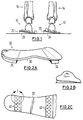
- Figure 1 is a generalized front elevational view of the lower extremities of a patient in need of alignment correction, including an orthotic according to the present invention.
- Figure 2a shows a typical orthotic according to the present invention in perspective side view, including front and back correcting wedges.
- Figure 2b shows the orthotic of Figure 2a in front elevational view.
- Figure 2c shows the orthotic of Figure 2a in bottom view with the correcting wedges removed.
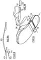
- FIG. 3 shows in detail an attachment portion of an orthotic according to the present invention.
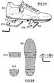
- Figure 4 shows the orthotic attachments of the present invention incorporated into the sole of an otherwise conventional shoe.
- Figure 5 shows from rear elevational view one example of the alignment correction available with the adjustable orthotic of the present invention.
- Figures 6A-D show an alternative implementation for attaching a post to an orthotic which has been found especially useful in many situations .
- Figures 7A-B show an alternative method of attaching posts to an orthotic .
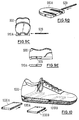
- Figures 8A-B show an orthotic having a toe extension .
- Figure 9A-E shows a method of attaching a post involving bolts .
- Figure 10 shows a shoe having posts affixed by side insertion .
- FIG. 1 the generalized bone structure of the lower extremities of a patient 5 can be seen in front elevational view together with an orthotic according to the present invention.
- Two feet 10 and 12 support respective legs 14 and 16.
- the feet can be seen to need correction of alignment relative to the ground and to the remainder of the body.
- the right foot 10 is shown in valgus, while the left foot is shown in varus.
- a pair of orthotic devices, indicated generally at 20 and 22, for left and right feet, respectively, can be seen below the respective feet, with rear foot and forefoot posts or wedges 24 and 26 in place for adjustment of the foot alignment and lower extremity alignment.
- FIG. 6 one example of the type of alignment correction available with present invention can be seen.
- a foot 10 shown in dashed line form within the shoe 17, requires correction.
- the wedge 26 By adding the wedge 26, the plane of the ground is raised to meet the sole of the foot 10, as shown by the line 27. This in turn causes the alignment of the foot 10 to change as shown by the line 29.
- the capability of adding a rear wedge 26 also provides the possibility of adding a heel lift for independent adjustment of heel height.
- the orthotic device 20 which for purposes of example only is an orthotic device for the right foot, includes a footsole portion 30 together with the pair of correcting wedges 24 and 26.
- the wedges 24 and 26 can be seen ( Figure 2b) to change the angle of the bottom of the footsole portion 30 relative to the ground, thus bringing the ground up to meet the soles of the patient's foot.
- the wedges 24 and 26 can be formed at any angle, depending on the patient's needs.
- the orientation of the wedges 24 or 26 can change depending upon whether valgus or varus correction is required. In at least some instances it may be desirable to provide an indicia for readily differentiating wedges of different angles, such as by making wedges of different correction factor in different colors.
- the bottom of the footsole portion 30 can be seen to have formed therein a pattern of recesses 40, which in the exemplary embodiment shown here are circular but may in other embodiments be of any acceptable form factor.
- the top portion of the posts or wedges 24 and 26 can also be seen to have a pattern of raised members 42 mated to the pattern of recesses 40, such that the wedges 24 or 26 can be affixed to the footsole portion 30 and will mechanically adhere thereto through the stress of walking, running or other ambulatory movement, while at the same time being readily removable when required for adjustment or other treatment.
- VelcroTM and the related class of "hook-and-loop" fasteners are acceptable attachment devices in at least some instances, as are T-slot connectors or any other device which provides a firm mechanical attachment which will withstand the stresses of walking or similar activities.
- the footsole portion 30 may comprise any of a number of materials, and can be formed by casting, extrusion, or other molding processes.
- materials are acceptable, including nylon, polystyrene, high density polyethylene, and numerous other polymers, but the presently preferred material is cast polyethylene terephthalate.
- the polyethylene terephthalate it is preferable for the polyethylene terephthalate to be fiber filled, although fiber content is not necessary in all cases.
- the footsole portion 30 may be either preformed or custom molded, depending on the needs of the patient and the economic issues associated with custom molding.
- orthotic attachments 50 and 52 into the sole of a shoe 54, in which case the footsole portion may be separated from the wedges.
- shoe of Figure 4 shoes VelcroTM as a means of attachment for purposes of example, the presently preferred method of attachment is the mating raised members and recesses discussed above in connection with Figure 3.
- an adjustable arch support in accordance with the present invention simply by providing a removable arch attachment and providing mating attachment members to a removable arch attachment and to the appropriate portion of the footsole portion 30.
- a completely adjustable, substantially custom fitted orthotic may be provided without the cost or delay normally associated with custom orthotics, while at the same time providing a highly effective method for optimizing balance and support for the patient.
- FIGS 6A-6D An alternative method of attaching posts to an orthotic can be appreciated from Figures 6A-6D, in which the bottom an orthotic 600 is shown in Figure 6A. Integrally formed into the orthotic 600 are forefoot grooves 610 at the forefoot portion 620 and rearfoot grooves 630 at the ankle portion 640 of the orthotic 600. One or more such grooves may be provided at each portion, as illustrated in the single rearfoot groove and the double forefoot grooves.
- a forefoot post 670A can be provided to mate to the orthotic 600 in a similar manner.
- the approach of Figure 6C also illustrates that a post need not extend across the entire sole of the orthotic, but instead may extend only part way.
- a plurality of partial posts may be provided for attachment next to one another, as shown by posts 670A-B and 680A-B.
- an arch wedge 690 may be provided if desired.
- FIG. 7A-B do not fall within the scope of the claims, but show a further arrangement for affixing a heel post to the shoe.
- a shoe 700 includes at the heel thereof a mounting portion 710.
- a heel post 720 which forms substantially the entire heel of the shoe, slides over the mounting portion 710 and is locked into place with one or more fasteners 730, such as screws, dowels or other similar devices.
- this approach permits easy replacement of an entire heel, whether as the result of wear or adjustment of the angle of the heel post.
- an orthotic having a toe extension can be better appreciated. It will be appreciated by those skilled in the art that in some cases support for the toes is required, and yet conventional, customized orthotics are too rigid to permit them to extend into the toe area because of the required flexing of the orthotic at the junction of the toes to the remainder of the foot.
- an orthotic 800 having attached thereto a forefoot post 810 mates to a toe extension portion 820 such that a continuous surface is provided between the front of the orthotic 800 and the toe extension 820.
- the toe extension 820 may be formed integrally with a forefoot post 830, or in some instances and depending upon the material from which the orthotic is made, may be formed integrally with the orthotic. Additionally, the toe extension 820 may be formed independently of the forefoot post, but configured to be inserted between the attachment devices of the post and the orthotic as shown in Figure 6. Such an arrangement is shown in Figure 8B.
- Figure 9A-E methods for attaching rearfoot and forefoot posts to a shoe using bolts are shown.
- Figure 9A-B show from the right side and in partial cross-section view a shoe 900 of the type shown in Figure 4, but wherein the posts 910A-B are affixed to the sole of the shoe by bolts or screws 920.
- Allen bolts are shown, any suitable screw or bolt is acceptable.
- Figures 9C-E still show a further arrangement for affixing a heel post to the shoe (900).
- FIG. 10 another approach to affixing corrective posts to a shoe otherwise of the type shown in Figure 4 may be appreciated.
- slots 1010A and 1010B are provided in the sole 1020, and posts 1030A and 1030B may be inserted into the slots 1010A-B, respectively. Due to the cross-sectional sizing of the posts 1030, the insertion of such posts causes a distortion of the sole of the foot appropriate to the required correction.
- While the posts 1030A and 1030B are sized sufficiently large that they wedge into place and should remain in place until intentionally removed, if additional security of attachment is desired a dowel or other device may be inserted into the sole 1020 and thence into the respective post 1030 to ensure that the respective post does not inadvertently work its way out of the slot .
Landscapes
- Health & Medical Sciences (AREA)
- Nursing (AREA)
- Orthopedic Medicine & Surgery (AREA)
- Engineering & Computer Science (AREA)
- Biomedical Technology (AREA)
- Heart & Thoracic Surgery (AREA)
- Vascular Medicine (AREA)
- Life Sciences & Earth Sciences (AREA)
- Animal Behavior & Ethology (AREA)
- General Health & Medical Sciences (AREA)
- Public Health (AREA)
- Veterinary Medicine (AREA)
- Orthopedics, Nursing, And Contraception (AREA)
- Dowels (AREA)
- Finger-Pressure Massage (AREA)
- Footwear And Its Accessory, Manufacturing Method And Apparatuses (AREA)
Abstract
Description
- This application relates to methods for forming orthopedic devices for use with shoes and other footwear, and to methods for forming such orthopedic devices.
- Orthopedic devices for the feet (hereinafter sometimes called "orthotics") are well known, and have been used by laypersons and podiatrists for many years. Orthotics of this type range from a simple arch support to a custom formed support for the foot. It has been estimated that 50% of the population could benefit from some form of shoe orthopedic device to improve support and balance for the foot.
- Since the feet are the foundation on which the rest of the body is supported, foot misalignment can result in many forms of discomfort for the patient. Symptoms which have been known to develop from such misalignment are plantar fasciitis, hammertoes, bunions, achilles tendonitis, and others. Misalignment can also cause or exacerbate knee, hip or back problems.
- In an ideal situation, orthotics can cure two forms of misalignment. First, the orthotic should match the sole of the foot to the ground and, second, the orthotic should bring the remainder of the body into proper alignment with the foot. It will be appreciated that the feet, legs and upper body represent a closed kinetic chain in which a change at any one point can affect the remaining points. Obtaining proper alignment of the foot with the ground can be simplifed to "bringing the ground up to meet the foot", while obtaining proper alignment of the foot with the rest of the body involves adjusting the relative position of the foot to the legs.
- Many pre-formed orthotics are available to remedy a variety of patient maladies relating to posture, stance and gait. Most such pre-formed orthotics are formed of a polymeric material and sold in a variety of sizes and shapes, with the expectation that one or another of the pre-cast shapes will be close enough to the patient's needs that the orthotic will be acceptable.
- However, in most such instances, the fit -- and thus the amount of improvement -- provided by the mass produced orthotic is far less than perfect. Typical problems involve the conformity of the orthotic to the sole of the foot, which affects the uniformity of support, and well as the amount of correction provided. Since only a few sizes of mass produced orthotics can be justified from an economic standpoint, this requires the patient to accept a significant amount of compromise in comfort and fit, and leads many patients to abandon use of the pre-formed orthotic.
- Custom fitted orthotics are also available, but typically are very expensive. In the conventional approach, a custom orthotic is constructed by starting with a complete cast of the foot. Such custom orthotics are frequently, though not always, done under the supervision of a podiatrist. The impression which results from the rusting is then sent to a laboratory where the custom formed orthotic is developed from the impression. As a result, the custom orthotic typically conforms to the sole of the patient's foot much better than a mass produced orthotic. Such custom orthotics, however, have two serious limitations. While the fit is much better in most instances, if an error is made either in making the initial casting, or making the orthotic from the casting, the resulting orthotic is substantially useless. Second, and often more important, changes in the patient's physiology require that the custom orthotic be recast. This latter limitation with the existing art can also affect patients using mass produced orthotics, and is particularly applicable to children. Children typically outgrow custom inlays in approximately one year. Given the expense of such custom orthotics, the economic burden can become substantial for either type of recasting.
- In order to correct specific abnormalities of the human foot, the use of separate movable wedge-shaped cushion pads is known (US-A-4 333 472). These pads made of a resilient foam material are placed individually in the inside of the shoe and affixed.
- It is further known, to use shoe inserts in the form of a pad shaped to provide an arch support of the foot. This insert is not able to correct the alignment between the foot and the ground.
- An orthotic according to the pre-characterising portion of claim 1 is known from DE-C-279735, which discloses a heel-bone support device having a cap made from springy metal which takes up the heel-bone. At the bottom of the cap is a flap. Between the flap and the bottom of the cap a wedge can be inserted.
- Further an orthotic according to the pre-characterising portion of claim 2 is known WO-A-8 901 745. This orthotic corresponds to a foot bed sole conform to the shape of the human foot. This orthotic is inserted into a sheath made of flexible material which is then affixed to the sole of the shoe.
- The aim of the present invention is to overcome many of the limitations of the prior art, and provides nearly all of the benefits of custom orthotics, while at the same time permitting adjustment of the orthotic after initial construction.
- The present invention provides a fully custom, adjustable orthotic specially fitted to the patient, yet capable of being adjusted to ensure continued proper fit and support, and may be configured as a footsole to be placed in a shoe as defined in appended claim 1, or as part of the sole of a conventional shoe as defined in appended claim 2.
- In particular, a pre-existing footsole portion of an orthotic formed of polyethylene terephthalate or other acceptable polymer has included in the bottom thereof attachment means. The posts or wedges, which may vary in configuration and amount of correction, include on the top thereof an attachment device capable of mating with the attachment device on the underside of the footsole portion. When attached, the post and footsole become substantially an integrated orthotic.
- The invention provides devices for instances, where both the foreward portion of the foot and the heel need alignment correction. In such instances, the orthotic of the present invention includes multiple attachment devices to permit correction of alignment at both locations.
- The attachment device may use any of a variety of techniques, including but not limited to interlocking dimples, Velcro™, bolts, interlocking geometries and dowels. The primary requirement of such attachment devices is that they remain firmly attached under the stress of walking and running, including remaining attached during the flexing of the orthotic which occurs with such activities.
- By replacing one wedge with others having different correction factors, such as different wedge angles, an adjustable orthotic is provided which can be specially fitted to the patient. As a result, improved fit and support can be provided. For convenience, different colors may be used for different correction factors.
- In addition, in the event the patient's physiology changes, the orthotic of the present invention can be modified readily to provide continued excellent support, thus substantially reducing the economic burden associated with both custom and mass produced orthotics. This can be particularly helpful for children. Additionally, the lower cost of the present device will make correction of gait problems in children much more accessible to a significant segment of the population.
- Still further, the adjustable orthotic of the present invention may be configured as part of the sole of an otherwise conventional shoe. In such an arrangement, the sole of the shoe may be specially configured to permit detachable forefoot and heel portions to be added and adjusted in a manner otherwise similar to the orthotic.
- There has therefore been a need for an orthotic which can be adjusted readily by a podiatrist to provide a substantially custom correction of a patient problem.
- In addition, there has been a need for an orthotic which can be readily modified by altering the amount of correction.
- Still further, there has been a need for an orthotic which can be readily altered by removing a first wedge and substituting therefor an alternative wedge such as might be necessary to provide a different amount of correction.
- Yet further, there has been a need for an orthotic which can be integrated into the sole of an otherwise substantially conventional shoe.
- These and other objects of the invention will be better understood from the following Detailed Description of the invention, taken together with the appended Figures.
- Figure 1 is a generalized front elevational view of the lower extremities of a patient in need of alignment correction, including an orthotic according to the present invention.
- Figure 2a shows a typical orthotic according to the present invention in perspective side view, including front and back correcting wedges.
- Figure 2b shows the orthotic of Figure 2a in front elevational view.
- Figure 2c shows the orthotic of Figure 2a in bottom view with the correcting wedges removed.
- Figure 3 shows in detail an attachment portion of an orthotic according to the present invention.
- Figure 4 shows the orthotic attachments of the present invention incorporated into the sole of an otherwise conventional shoe.
- Figure 5 shows from rear elevational view one example of the alignment correction available with the adjustable orthotic of the present invention.
- Figures 6A-D show an alternative implementation for attaching a post to an orthotic which has been found especially useful in many situations.
- Figures 7A-B show an alternative method of attaching posts to an orthotic.
- Figures 8A-B show an orthotic having a toe extension.
- Figure 9A-E shows a method of attaching a post involving bolts.
- Figure 10 shows a shoe having posts affixed by side insertion.
- Referring first to Figure 1, the generalized bone structure of the lower extremities of a patient 5 can be seen in front elevational view together with an orthotic according to the present invention. Two
feet respective legs right foot 10 is shown in valgus, while the left foot is shown in varus. A pair of orthotic devices, indicated generally at 20 and 22, for left and right feet, respectively, can be seen below the respective feet, with rear foot and forefoot posts orwedges foot 10, shown in dashed line form within theshoe 17, requires correction. By adding thewedge 26, the plane of the ground is raised to meet the sole of thefoot 10, as shown by theline 27. This in turn causes the alignment of thefoot 10 to change as shown by theline 29. It will be appreciated that the capability of adding arear wedge 26 also provides the possibility of adding a heel lift for independent adjustment of heel height. - With reference now to Figures 2a-2c, the
orthotic device 20, which for purposes of example only is an orthotic device for the right foot, includes afootsole portion 30 together with the pair of correctingwedges wedges footsole portion 30 relative to the ground, thus bringing the ground up to meet the soles of the patient's foot. It will be appreciated that thewedges wedges - Referring particularly to Figures 2c and 3, a preferred type of attachment device is shown in detail. The bottom of the
footsole portion 30 can be seen to have formed therein a pattern ofrecesses 40, which in the exemplary embodiment shown here are circular but may in other embodiments be of any acceptable form factor. The top portion of the posts orwedges members 42 mated to the pattern ofrecesses 40, such that thewedges footsole portion 30 and will mechanically adhere thereto through the stress of walking, running or other ambulatory movement, while at the same time being readily removable when required for adjustment or other treatment. - Although a pattern of mating recessed and raised members is presently preferred as a method of affixing the
wedges footsole 30, other approaches are also acceptable. For example, Velcro™ and the related class of "hook-and-loop" fasteners are acceptable attachment devices in at least some instances, as are T-slot connectors or any other device which provides a firm mechanical attachment which will withstand the stresses of walking or similar activities. - The
footsole portion 30 may comprise any of a number of materials, and can be formed by casting, extrusion, or other molding processes. A variety of materials are acceptable, including nylon, polystyrene, high density polyethylene, and numerous other polymers, but the presently preferred material is cast polyethylene terephthalate. For at least some applications, it is preferable for the polyethylene terephthalate to be fiber filled, although fiber content is not necessary in all cases. - The
footsole portion 30 may be either preformed or custom molded, depending on the needs of the patient and the economic issues associated with custom molding. In addition, in some embodiments it may also be desirable to make the raisedmembers 42 out of different, more rigid material which may be embedded either in thefootsole portion 30 or the orthotic attachments orwedges footsole portion 30 andattachments - Referring next to Figure 4, in some embodiments it may be desirable to integrate
orthotic attachments shoe 54, in which case the footsole portion may be separated from the wedges. Although the shoe of Figure 4 shoes Velcro™ as a means of attachment for purposes of example, the presently preferred method of attachment is the mating raised members and recesses discussed above in connection with Figure 3. - While in many instances it will be desirable to use the same material for the posts as for the footsole, in some instances it may be desirable to vary the materials for the respective portions. For example, improved shock absorption may be provided by using posts of a hard rubber combined with footsole constructed of a thermoplastic material. The easy replacement of the posts also provides an easy method for minimizing normal wear and tear, particularly on the shoe of Figure 5, in that a worn post can simply be removed and a replacement snapped into place.
- Additionally, it is possible to provide an adjustable arch support in accordance with the present invention simply by providing a removable arch attachment and providing mating attachment members to a removable arch attachment and to the appropriate portion of the
footsole portion 30. - By combining the
footsole portion 30 with theadjustable wedges - An alternative method of attaching posts to an orthotic can be appreciated from Figures 6A-6D, in which the bottom an orthotic 600 is shown in Figure 6A. Integrally formed into the orthotic 600 are forefoot
grooves 610 at theforefoot portion 620 andrearfoot grooves 630 at theankle portion 640 of the orthotic 600. One or more such grooves may be provided at each portion, as illustrated in the single rearfoot groove and the double forefoot grooves. Amating rearfoot post 650 shown in Figure 6B, having aridge 660 formed thereon, connects to the orthotic 600 at the ankle orrearfoot portion 640 thereof by interlocking theridge 660 into thegroove 630. Alternatively, in some instances it is possible that the ridges could be placed on the orthotic and the grooves on the post. As can be appreciated from Figure 6C, a forefoot post 670A can be provided to mate to the orthotic 600 in a similar manner. The approach of Figure 6C also illustrates that a post need not extend across the entire sole of the orthotic, but instead may extend only part way. Additionally, and as best illustrated in Figures 6C and 6D, a plurality of partial posts may be provided for attachment next to one another, as shown by posts 670A-B and 680A-B. In addition, an arch wedge 690 may be provided if desired. - The embodiments of figures 7A-B do not fall within the scope of the claims, but show a further arrangement for affixing a heel post to the shoe. A
shoe 700 includes at the heel thereof a mountingportion 710. Aheel post 720, which forms substantially the entire heel of the shoe, slides over the mountingportion 710 and is locked into place with one ormore fasteners 730, such as screws, dowels or other similar devices. As with other embodiments described above, this approach permits easy replacement of an entire heel, whether as the result of wear or adjustment of the angle of the heel post. - Referring next to Figures 8A-B, an orthotic having a toe extension according to the present invention can be better appreciated. It will be appreciated by those skilled in the art that in some cases support for the toes is required, and yet conventional, customized orthotics are too rigid to permit them to extend into the toe area because of the required flexing of the orthotic at the junction of the toes to the remainder of the foot. In accordance with the present invention, an orthotic 800 having attached thereto a
forefoot post 810 mates to atoe extension portion 820 such that a continuous surface is provided between the front of the orthotic 800 and thetoe extension 820. Thetoe extension 820 may be formed integrally with aforefoot post 830, or in some instances and depending upon the material from which the orthotic is made, may be formed integrally with the orthotic. Additionally, thetoe extension 820 may be formed independently of the forefoot post, but configured to be inserted between the attachment devices of the post and the orthotic as shown in Figure 6. Such an arrangement is shown in Figure 8B. - With reference next to Figure 9A-E, methods for attaching rearfoot and forefoot posts to a shoe using bolts are shown. Figure 9A-B show from the right side and in partial cross-section view a
shoe 900 of the type shown in Figure 4, but wherein theposts 910A-B are affixed to the sole of the shoe by bolts or screws 920. Although Allen bolts are shown, any suitable screw or bolt is acceptable. - Figures 9C-E still show a further arrangement for affixing a heel post to the shoe (900).
- Referring next to Figure 10, another approach to affixing corrective posts to a shoe otherwise of the type shown in Figure 4 may be appreciated. In the
shoe 1000 shown partial cross-sectional perspective view in Figure 10, slots 1010A and 1010B are provided in the sole 1020, and posts 1030A and 1030B may be inserted into the slots 1010A-B, respectively. Due to the cross-sectional sizing of theposts 1030, the insertion of such posts causes a distortion of the sole of the foot appropriate to the required correction. While the posts 1030A and 1030B are sized sufficiently large that they wedge into place and should remain in place until intentionally removed, if additional security of attachment is desired a dowel or other device may be inserted into the sole 1020 and thence into therespective post 1030 to ensure that the respective post does not inadvertently work its way out of the slot. - Having fully described one embodiment of the present invention, it will be apparent to those of ordinary skill in the art that numerous alternatives and equivalents exist which do not depart from the invention set forth above. It is therefore to be understood that the invention is not to be limited by the foregoing description, but only by the appended claims.
Claims (12)
- An adjustable orthopedic device for the foot comprising a footbed portion (30) formed to conform substantially to the sole of a patient's foot and having first attachment means in a rearfoot area on the bottom thereof, and wedge means (26) having second attachment means on the top thereof, said second attachment means being arranged to mate with the first attachment means to affix the wedge means (26) to the rearfoot area of the footbed portion (30) in such a manner that the wedge means (26) can be removed characterized in that the footbed portion has also first attachment means in a forefoot area on its bottom side which mate with second attachment means on the top of additional removable wedge means (24) in the forefoot area of the footbed portion and that the attachment means are capable of mating with the wedge means (24, 26) for treating varus or valgus misalignments.
- An adjustable orthopedic device for the foot comprising a shoe (54, 700) having a sole (710), characterized by the sole having first attachment means in a rearfoot area and in a forefoot area on the bottom thereof, and wedge means (24, 26) having second attachment means on the top thereof, the second attachment means being arranged to mate with the first attachment means thereby to affix the wedge means (24, 26) to the rearfoot area and to the forefoot area of the sole of the shoe (54) during walking while at the same time permitting the wedge means (910) to be removed when desired, and whereby the attachment means are capable of mating with the wedge means (910A, 910B) for treating varus or valgus misalignments.
- The orthopedic device of claim 1 or 2, wherein one of said first and second attachment means comprises raised members (42) and the other of said first and second attachment means comprises recesses (40, 720).
- The orthopedic device of one of the claims 1 to 3, wherein one of said first and second attachment means comprises a hook portion and the other of said first and second attachment means comprises a loop portion.
- The orthopedic device of claim 1 to 3, wherein the first attachment means is a groove (610, 630) and the second attachment means is a ridge (660) mated to the groove (610, 630) of the first attachment means.
- The orthopedic device of claim 1 to 3, wherein the first attachment means is a threaded receiver and the second attachment means is a bolt extending through at least a portion of the wedge means (24, 26).
- The orthopedic device of claim 2, wherein the first attachment means is a recess within the sole (710) of the shoe (54, 700) and the second attachment means is the perimeter sizing of the wedge means, such that the wedge means is affixed to the sole (710) by being inserted into the recess.
- The orthopedic device of claim 2, wherein the first attachment means is a slot within the sole of the shoe and the second attachment means is the cross-sectional sizing of the posts.
- The orthopedic device of claim 1 to 8, wherein the footbed portion (30) is made from polyethylene terephthalate.
- The orthopedic device of claim 1 to 8, wherein the footbed portion (30) is made from nylon.
- The orthopedic device of claim 1 to 10, wherein the wedge means (24, 26) are of different colors for different amounts of correction.
- The orthopedic device of claim 1 or 3 to 6, or 9 to 11, wherein the footbed portion includes an arch wedge.
Applications Claiming Priority (2)
| Application Number | Priority Date | Filing Date | Title |
|---|---|---|---|
| US80442391A | 1991-12-10 | 1991-12-10 | |
| US804423 | 1991-12-10 |
Publications (2)
| Publication Number | Publication Date |
|---|---|
| EP0550842A1 EP0550842A1 (en) | 1993-07-14 |
| EP0550842B1 true EP0550842B1 (en) | 1996-10-23 |
Family
ID=25188947
Family Applications (1)
| Application Number | Title | Priority Date | Filing Date |
|---|---|---|---|
| EP92121017A Expired - Lifetime EP0550842B1 (en) | 1991-12-10 | 1992-12-09 | Adjustable orthotic |
Country Status (3)
| Country | Link |
|---|---|
| EP (1) | EP0550842B1 (en) |
| AT (1) | ATE144401T1 (en) |
| DE (1) | DE69214794T2 (en) |
Families Citing this family (3)
| Publication number | Priority date | Publication date | Assignee | Title |
|---|---|---|---|---|
| US5382225A (en) * | 1992-07-14 | 1995-01-17 | Sutcliffe; Brian L. | Universal night splint |
| FR2805753B1 (en) * | 2000-03-06 | 2002-05-17 | Salomon Sa | CABLE SOLE ASSEMBLY |
| CN104544726A (en) * | 2013-10-28 | 2015-04-29 | 文洪熙 | Insole for correction |
Citations (2)
| Publication number | Priority date | Publication date | Assignee | Title |
|---|---|---|---|---|
| DE279735C (en) * | ||||
| GB620329A (en) * | 1946-12-23 | 1949-03-23 | Charles Ian Stewart | Improvements in transverse and longitudinal foot arch supports |
Family Cites Families (5)
| Publication number | Priority date | Publication date | Assignee | Title |
|---|---|---|---|---|
| US4333472A (en) * | 1979-12-31 | 1982-06-08 | Tager Steven E | Compensatory-corrective orthopedic foot devices |
| JPS6036081Y2 (en) * | 1982-06-26 | 1985-10-26 | 美津濃株式会社 | shoe insole |
| DE8509263U1 (en) * | 1985-03-28 | 1985-05-09 | Globus Fußstützenfabrik Karl Kremendahl, 5630 Remscheid | Orthopedic shoe insole |
| FR2600506A1 (en) * | 1986-06-30 | 1987-12-31 | Own Joseph | Improved adjustable plantar sole |
| US4813162A (en) * | 1987-08-25 | 1989-03-21 | Evelyn D. Gliege | Device for receiving an orthotic insert |
-
1992
- 1992-12-09 AT AT92121017T patent/ATE144401T1/en not_active IP Right Cessation
- 1992-12-09 EP EP92121017A patent/EP0550842B1/en not_active Expired - Lifetime
- 1992-12-09 DE DE69214794T patent/DE69214794T2/en not_active Expired - Fee Related
Patent Citations (2)
| Publication number | Priority date | Publication date | Assignee | Title |
|---|---|---|---|---|
| DE279735C (en) * | ||||
| GB620329A (en) * | 1946-12-23 | 1949-03-23 | Charles Ian Stewart | Improvements in transverse and longitudinal foot arch supports |
Also Published As
| Publication number | Publication date |
|---|---|
| ATE144401T1 (en) | 1996-11-15 |
| DE69214794T2 (en) | 1997-02-20 |
| DE69214794D1 (en) | 1996-11-28 |
| EP0550842A1 (en) | 1993-07-14 |
Similar Documents
| Publication | Publication Date | Title |
|---|---|---|
| US5345701A (en) | Adjustable orthotic | |
| US6105283A (en) | Shoe insole for correction, control, and underfoot comfort | |
| US6880266B2 (en) | Footwear sole | |
| US5014706A (en) | Orthotic insole with regions of different hardness | |
| US4791736A (en) | Ski boot orthotic | |
| USRE33648E (en) | Variably adjustable shoe inserts | |
| US6349487B1 (en) | Foot leverage system and method | |
| EP0500632B1 (en) | Method of forming orthotic devices | |
| US4510700A (en) | Variably adjustable shoe inserts | |
| US6594922B1 (en) | Medial/lateral counter foot stabilizer | |
| US4982737A (en) | Orthotic support construction | |
| US6173511B1 (en) | Orthosis for footwear with positional self-adjustment | |
| US5058585A (en) | Orthotic shoe insert | |
| US6860864B2 (en) | D-DAFO (DeRoss-dynamic ankle foot orthosis) | |
| AU674283B2 (en) | Orthotic device | |
| EP0173396A2 (en) | Variable adjustable shoe inserts | |
| WO2007044983A2 (en) | User moldable adjustable orthopedic insert | |
| CA1128825A (en) | Orthopedic appliance | |
| EP0550842A1 (en) | Adjustable orthotic | |
| EP1795083B1 (en) | Footwear sole | |
| WO2008090431A2 (en) | Method for manufacturing an orthopaedic brace for treating infirmity to lower limbs and orthopaedic brace thus obtained | |
| US20230338181A1 (en) | Orthosis and method of use | |
| EP1038459A1 (en) | Foot leverage assembly and method of improving motion using the assembly | |
| GB2375711A (en) | Paediatric corrective footwear system | |
| CA2358669C (en) | Orthosis for footwear with positional self-adjustment |
Legal Events
| Date | Code | Title | Description |
|---|---|---|---|
| PUAI | Public reference made under article 153(3) epc to a published international application that has entered the european phase |
Free format text: ORIGINAL CODE: 0009012 |
|
| AK | Designated contracting states |
Kind code of ref document: A1 Designated state(s): AT CH DE DK ES FR GB IT LI NL SE |
|
| 17P | Request for examination filed |
Effective date: 19931127 |
|
| 17Q | First examination report despatched |
Effective date: 19940329 |
|
| GRAH | Despatch of communication of intention to grant a patent |
Free format text: ORIGINAL CODE: EPIDOS IGRA |
|
| GRAH | Despatch of communication of intention to grant a patent |
Free format text: ORIGINAL CODE: EPIDOS IGRA |
|
| GRAA | (expected) grant |
Free format text: ORIGINAL CODE: 0009210 |
|
| AK | Designated contracting states |
Kind code of ref document: B1 Designated state(s): AT CH DE DK ES FR GB IT LI NL SE |
|
| PG25 | Lapsed in a contracting state [announced via postgrant information from national office to epo] |
Ref country code: IT Free format text: LAPSE BECAUSE OF FAILURE TO SUBMIT A TRANSLATION OF THE DESCRIPTION OR TO PAY THE FEE WITHIN THE PRE;WARNING: LAPSES OF ITALIAN PATENTS WITH EFFECTIVE DATE BEFORE 2007 MAY HAVE OCCURRED AT ANY TIME BEFORE 2007. THE CORRECT EFFECTIVE DATE MAY BE DIFFERENT FROM THE ONE RECORDED.SCRIBED TIME-LIMIT Effective date: 19961023 Ref country code: AT Effective date: 19961023 Ref country code: NL Free format text: LAPSE BECAUSE OF FAILURE TO SUBMIT A TRANSLATION OF THE DESCRIPTION OR TO PAY THE FEE WITHIN THE PRESCRIBED TIME-LIMIT Effective date: 19961023 Ref country code: LI Free format text: LAPSE BECAUSE OF FAILURE TO SUBMIT A TRANSLATION OF THE DESCRIPTION OR TO PAY THE FEE WITHIN THE PRESCRIBED TIME-LIMIT Effective date: 19961023 Ref country code: DK Effective date: 19961023 Ref country code: ES Free format text: THE PATENT HAS BEEN ANNULLED BY A DECISION OF A NATIONAL AUTHORITY Effective date: 19961023 Ref country code: FR Effective date: 19961023 Ref country code: CH Free format text: LAPSE BECAUSE OF FAILURE TO SUBMIT A TRANSLATION OF THE DESCRIPTION OR TO PAY THE FEE WITHIN THE PRESCRIBED TIME-LIMIT Effective date: 19961023 |
|
| REF | Corresponds to: |
Ref document number: 144401 Country of ref document: AT Date of ref document: 19961115 Kind code of ref document: T |
|
| REF | Corresponds to: |
Ref document number: 69214794 Country of ref document: DE Date of ref document: 19961128 |
|
| PG25 | Lapsed in a contracting state [announced via postgrant information from national office to epo] |
Ref country code: SE Effective date: 19970123 |
|
| EN | Fr: translation not filed | ||
| NLV1 | Nl: lapsed or annulled due to failure to fulfill the requirements of art. 29p and 29m of the patents act | ||
| REG | Reference to a national code |
Ref country code: CH Ref legal event code: PL |
|
| PLBE | No opposition filed within time limit |
Free format text: ORIGINAL CODE: 0009261 |
|
| STAA | Information on the status of an ep patent application or granted ep patent |
Free format text: STATUS: NO OPPOSITION FILED WITHIN TIME LIMIT |
|
| 26N | No opposition filed | ||
| REG | Reference to a national code |
Ref country code: GB Ref legal event code: IF02 |
|
| PGFP | Annual fee paid to national office [announced via postgrant information from national office to epo] |
Ref country code: GB Payment date: 20041207 Year of fee payment: 13 |
|
| PGFP | Annual fee paid to national office [announced via postgrant information from national office to epo] |
Ref country code: DE Payment date: 20050122 Year of fee payment: 13 |
|
| PG25 | Lapsed in a contracting state [announced via postgrant information from national office to epo] |
Ref country code: GB Free format text: LAPSE BECAUSE OF NON-PAYMENT OF DUE FEES Effective date: 20051209 |
|
| PG25 | Lapsed in a contracting state [announced via postgrant information from national office to epo] |
Ref country code: DE Free format text: LAPSE BECAUSE OF NON-PAYMENT OF DUE FEES Effective date: 20060701 |
|
| GBPC | Gb: european patent ceased through non-payment of renewal fee |
Effective date: 20051209 |