EP0550250B1 - Propulsion system for spacecraft - Google Patents
Propulsion system for spacecraft Download PDFInfo
- Publication number
- EP0550250B1 EP0550250B1 EP92311731A EP92311731A EP0550250B1 EP 0550250 B1 EP0550250 B1 EP 0550250B1 EP 92311731 A EP92311731 A EP 92311731A EP 92311731 A EP92311731 A EP 92311731A EP 0550250 B1 EP0550250 B1 EP 0550250B1
- Authority
- EP
- European Patent Office
- Prior art keywords
- thrusters
- propellant
- spacecraft
- thruster
- power supply
- Prior art date
- Legal status (The legal status is an assumption and is not a legal conclusion. Google has not performed a legal analysis and makes no representation as to the accuracy of the status listed.)
- Expired - Lifetime
Links
Images

Classifications
-
- F—MECHANICAL ENGINEERING; LIGHTING; HEATING; WEAPONS; BLASTING
- F03—MACHINES OR ENGINES FOR LIQUIDS; WIND, SPRING, OR WEIGHT MOTORS; PRODUCING MECHANICAL POWER OR A REACTIVE PROPULSIVE THRUST, NOT OTHERWISE PROVIDED FOR
- F03H—PRODUCING A REACTIVE PROPULSIVE THRUST, NOT OTHERWISE PROVIDED FOR
- F03H1/00—Using plasma to produce a reactive propulsive thrust
- F03H1/0006—Details applicable to different types of plasma thrusters
- F03H1/0018—Arrangements or adaptations of power supply systems
-
- B—PERFORMING OPERATIONS; TRANSPORTING
- B64—AIRCRAFT; AVIATION; COSMONAUTICS
- B64G—COSMONAUTICS; VEHICLES OR EQUIPMENT THEREFOR
- B64G1/00—Cosmonautic vehicles
- B64G1/22—Parts of, or equipment specially adapted for fitting in or to, cosmonautic vehicles
- B64G1/24—Guiding or controlling apparatus, e.g. for attitude control
- B64G1/26—Guiding or controlling apparatus, e.g. for attitude control using jets
-
- B—PERFORMING OPERATIONS; TRANSPORTING
- B64—AIRCRAFT; AVIATION; COSMONAUTICS
- B64G—COSMONAUTICS; VEHICLES OR EQUIPMENT THEREFOR
- B64G1/00—Cosmonautic vehicles
- B64G1/22—Parts of, or equipment specially adapted for fitting in or to, cosmonautic vehicles
- B64G1/40—Arrangements or adaptations of propulsion systems
- B64G1/411—Electric propulsion
- B64G1/415—Arcjets or resistojets
-
- B—PERFORMING OPERATIONS; TRANSPORTING
- B64—AIRCRAFT; AVIATION; COSMONAUTICS
- B64G—COSMONAUTICS; VEHICLES OR EQUIPMENT THEREFOR
- B64G1/00—Cosmonautic vehicles
- B64G1/22—Parts of, or equipment specially adapted for fitting in or to, cosmonautic vehicles
- B64G1/24—Guiding or controlling apparatus, e.g. for attitude control
- B64G1/242—Orbits and trajectories
- B64G1/2427—Transfer orbits
Definitions
- This invention relates to propulsion systems for spacecraft.
- the invention is particularly applicable to the type of propulsion system that produces a relatively low thrust in relation to its weight, making it unsuitable for lift-off of a spacecraft, i.e. the type of propulsion system that is suitable for making adjustments to the position and/or attitude of an orbiting spacecraft, and/or for varying the orbit.
- propulsion systems of relatively high specific impulse (a quantity which gives a measure of the impulse which can be produced from a given mass of propellant) which produce a low absolute value of thrust.
- propulsion systems include a kind which use electrical power to increase the specific impulse of the propellant by transferring energy into the propellant.
- Typical of such thrusters are ion engines, arc-jets and plasma engines.
- ion thrusters In ion thrusters, the ions are accelerated out of the thruster by electrostatic attraction between aligned grids at appropriate potentials. In arc-jets the exhaust velocity is increased by heating the propellant by generating an arc through it. In plasma engines, including magneto-plasma thrusters and stationary plasma thrusters, the ionised propellant is accelerated by means of a strong magnetic field.
- FIG. 1 It will be seen from Figure 1 that a north-south correction must be imparted in the direction of the arrows.
- the north-south direction is also shown on the spacecraft shown in Figure 2.
- the thrusters T generate thrust passing through the centre of gravity CG of the spacecraft. In applying a burst to one of the thrusters, a north component is generated, but a radial component is also generated. Build-up of the latter component can be offset by operating the south pointing thruster T at the opposite point in the orbit of the spacecraft.
- each thruster incorporates its own power supply for transferring electrical energy into the propellant by using propellant gas or vapour as part of the current carrying circuit.
- the invention provides a propulsion system for a spacecraft as claimed in the independent claim 1.
- Preferred embodiments form the subject matter of the dependent claims.
- transfer of energy into the propellant requires the creation of a current flow path through the propellant between electrodes; one power supply is capable of energizing the electrodes of the thrusters simultaneously, and switch means are arranged so that only one thruster at a time is supplied with propellant and can thus draw current through the propellant to enable thrust to be generated.
- the thrusters are of course arranged in a configuration permitting sequential operation.
- the spacecraft shown in Figure 3 has thrusters T1, T2 arranged in the same way as for the spacecraft shown schematically in Figure 2 i.e. the thrust acts through the centre of gravity of the spacecraft. It is standard practice in spacecraft to double-up on systems in order to minimize the risk of the spacecraft failing through failure at a single point and, to this end, redundant thrusters T3 and T4, also acting through the centre of gravity of the spacecraft are also provided. The latter thrusters do not come into operation unless one or both of the primary thrusters T1, T2 fails.
- the thrusters T1 to T4 may be ion thrusters, described in more detail with reference to Figure 5, which relies on an exhaust of accelerated propellant ions to produce thrust, or it may be an arc-jet thruster, or other electrically-powered thruster which relies on a separate power supply unit.
- the arc-jet is described in more detail with reference to Figure 4, in which case the propellant exhaust velocity is increased by heating of the propellant gas by means of an arc struck between two electrodes.
- ionisation in arc-jets while necessary for the flow of current which causes the heating of the propellant, should be kept to a minimum because more ionisation requires more power which is a loss and does not produce a proportional increase in thrust).
- the thrusters do not operate unless current flows through the propellant and, while it would be inconvenient to switch the electrodes on and off, since there are large potential differences between them and breakdown of the switching contacts could be caused, it is simply necessary to stop the flow of propellant to the relevant thruster because current is not drawn (except for negligible currents drawn through leakage paths) from the electrodes even when they are energized at their usual potential in the absence of propellant, because the current flows through the ionised propellant.
- the electrodes of all the thrusters are energized i.e. charged, when one thruster is brought into operation.
- the thruster which draws electrical power and produces thrust is the one which receives propellant. It may, however, be found to be desirable to switch on and off supplies to purely resistive loads such as cathode heaters and electro-magnets. Since these would be low voltage supplies, the risk of contact breakdown is minimal in this case.
- the propellant may be Xenon, Argon or Krypton, and may be stored in liquid form, or may be a solid such as Caesium or Mercury which is vapourised when heated.
- Figure 4 shows an arc-jet thruster suitable for use in the configuration of Figure 3.
- the arc-jet is supplied with hydrazine (N2H4) from pipe 5 into a valve 2 which supplies a catalyst bed 3 via an injector 6.
- the hydrazine dissociates on contact with the catalyst bed into ammonia, nitrogen and hydrogen, and the gases exhaust through the nozzle 4.
- the hydrazine is heated by means of an arc struck between electrodes.
- Alternative propellants to hydrazine could be used.
- the ion thruster T1 comprises a discharge chamber 8 to which propellant is supplied from a pipe 9 via a valve 10 and via further valves 11, 12 and 33 to form respective main propellant flows, cathode propellant flows, and neutraliser propellant flows.
- the arc is initially struck in the ion thruster by providing a potential difference between hollow cathode 13 and cathode keeper 14 and electrons flow to annular anode 15 through a magnetic field generated by electro-magnets 16, 17 which cause the electrons to undergo a spiralling path and increase the probability of collision with main propellant flow through opening 18 to provide the main ion beam.
- the latter passes through the perforated end of the discharge chamber 8a and through a perforated accelerator grid 19 which is maintained highly negative relative to the discharge chamber to accelerate the ion beam and hence provide the thrust of the thruster.
- the accelerator grid 19 ensures that there is a low divergence to the ion beam, hence preventing electrons from being attracted into the thruster.
- the resulting positive ion beam emerging from the thruster is neutralised by the further propellant flow through valve 33 and hollow cathode 20. An arc is struck between hollow cathode 20 and cathode keeper 21 to generate an electron flow.
- the power supply unit PSU1 feeds a number of subsidiary power supply units for the electrodes, as follows: the negative accelerator grid 22, the beam power supply unit 23, the cathode heater 24, the cathode keeper unit power supply unit 25, the anode power supply unit 26, the solenoid power supply unit 27, the neutraliser cathode heater 28 and the neutraliser keeper power supply unit 29.
- the power supply unit 1 also powers a thruster T2 provided with identical control circuitry to the left of power supply unit PSU1, but only the accelerator grid power supply unit 22a and beam power supply unit 23a have been shown.
- the accelerator grid power supply unit, beam power supply unit, anode power supply unit and cathode keeper power supply unit remain connected, because no current will be drawn from them.
- the same PSU1 also supplies power to thruster T2, but the heaters, the electro-magnets and the propellant valve 10a may be switched off via switches identical to the switches S4 to S7, and this thruster is brought into operation by closure of the switches.
- Power supply unit PSU1 could be supplied by the solar panels of the spacecraft or by an onboard battery charged by the solar panels.
- the various voltages provided within PSU1 are conveniently provided by a switched mode power converter.
- ion thrusters generally have dedicated power supplies and the single power supply for the two thrusters could provide non-ideal electrode potentials.
- the power supply therefore includes active control of the thruster by means of control loops corresponding to the three propellant flows described, magnet current adjustment and anode current adjustment.
- constant beam current from beam power supply unit 23 must be attained, and this is achieved by monitoring that current through a series resistor with control means 30 to vary the propellant flow by means of control valve 11 and/or magnet current by adjusting power supply unit 27.
- the voltage difference between the anode power supply unit 26 (constant current) and the cathode keeper power supply unit 25 (constant current) is held fixed by adjusting the cathode propellant flow via control means 31 and control valve 12, in order to ensure optimum propellant utilisation.
- the voltage difference between the neutraliser keeper 21 and the neutraliser cathode 20, caused by the neutraliser keeper power supply unit 29 in constant current mode, is held constant to maintain fixed neutraliser plasma conditions whilst minimising neutraliser dissipation, thus optimising neutraliser life by controlling the neutraliser cathode propellant flow rate via control means 32 and control valve 33.
- active control loops it would be possible to run two thrusters by setting up the power supply output to switch between two (or more) set points according to which thruster is in use.
- thrusters e.g. T5, T6 for east-west station keeping may also be supplied from power supply unit PSU1, it again being necessary that only one of the thrusters T1, T2, T5, T6 should be powered at any one time.
- switches S4, S6 and S7 could be omitted and connections to these power supply units made permanent, since the current drawn from these power supplies will only be small in practice.
- the invention is also applicable to an arrangement in which the ionised propellant is accelerated by means of a strong magnetic field, and active control of the thruster as described above may again be used, or alternatively set-point operation of more than one thruster is possible from one power supply.
Landscapes
- Engineering & Computer Science (AREA)
- Chemical & Material Sciences (AREA)
- Combustion & Propulsion (AREA)
- Remote Sensing (AREA)
- Aviation & Aerospace Engineering (AREA)
- Radar, Positioning & Navigation (AREA)
- Physics & Mathematics (AREA)
- Plasma & Fusion (AREA)
- Mechanical Engineering (AREA)
- General Engineering & Computer Science (AREA)
- Plasma Technology (AREA)
Description
- This invention relates to propulsion systems for spacecraft.
- The invention is particularly applicable to the type of propulsion system that produces a relatively low thrust in relation to its weight, making it unsuitable for lift-off of a spacecraft, i.e. the type of propulsion system that is suitable for making adjustments to the position and/or attitude of an orbiting spacecraft, and/or for varying the orbit. For this purpose, advantage can be taken of propulsion systems of relatively high specific impulse (a quantity which gives a measure of the impulse which can be produced from a given mass of propellant) which produce a low absolute value of thrust. Included among such propulsion systems are a kind which use electrical power to increase the specific impulse of the propellant by transferring energy into the propellant. Typical of such thrusters are ion engines, arc-jets and plasma engines. In ion thrusters, the ions are accelerated out of the thruster by electrostatic attraction between aligned grids at appropriate potentials. In arc-jets the exhaust velocity is increased by heating the propellant by generating an arc through it. In plasma engines, including magneto-plasma thrusters and stationary plasma thrusters, the ionised propellant is accelerated by means of a strong magnetic field.
- One example of adjustments which must be made to the position of an orbiting spacecraft concerns geostationary satellites, i.e. satellites in orbit around the equator at a radius of approximately 22,300 miles from the earth (Figure 1). Because the plane of the orbit S is inclined to the plane of the ecliptic E i.e. the earth's orbit around the sun (the earth's axis being inclined to the plane of its orbit), the orbit tends to be perturbed by the gravitation attraction of the sun, moon and planets, and it is found necessary to apply periodic east-west and, more frequently, north-south corrections to the spacecraft to maintain it in the necessary fixed solid angle as seen from the earth. For such so-called north-south station-keeping, it is conventional to provide a pair of thrusters, both on the north face, or both on the south face, or one on the north face and one on the south face of the spacecraft. In one arrangement where the thrusters do not act through the centre of gravity of the spacecraft, both thrusters must be fired simultaneously in order to avoid generating a moment about the centre of gravity of the spacecraft which would cause it to spin. In another arrangement where the thrusters do act through the centre of gravity of the spacecraft (Figure 3), no spin can take place, but the thrusters are operated at spaced points in the orbit of the spacecraft to cancel an unwanted east-west component imparted to the spacecraft. It will be seen from Figure 1 that a north-south correction must be imparted in the direction of the arrows. The north-south direction is also shown on the spacecraft shown in Figure 2. The thrusters T generate thrust passing through the centre of gravity CG of the spacecraft. In applying a burst to one of the thrusters, a north component is generated, but a radial component is also generated. Build-up of the latter component can be offset by operating the south pointing thruster T at the opposite point in the orbit of the spacecraft.
- In all cases, each thruster incorporates its own power supply for transferring electrical energy into the propellant by using propellant gas or vapour as part of the current carrying circuit.
- The invention provides a propulsion system for a spacecraft as claimed in the
independent claim 1. Preferred embodiments form the subject matter of the dependent claims. - In the thrusters of the present invention, transfer of energy into the propellant requires the creation of a current flow path through the propellant between electrodes; one power supply is capable of energizing the electrodes of the thrusters simultaneously, and switch means are arranged so that only one thruster at a time is supplied with propellant and can thus draw current through the propellant to enable thrust to be generated.
- Current cannot be drawn through the propellant of the thruster which is not supplied with propellant, and hence it is not necessary to switch the electrodes of that thruster between which the current flows in addition to stopping the flow of propellant, which electrodes may be at high voltages and thus risk breakdown of switching contacts if switched. This then makes it feasible to power both or all the thrusters with a single power supply providing a significant weight reduction of the spacecraft. The thrusters are of course arranged in a configuration permitting sequential operation.
- The switch means may be arranged to operate valve means in the propellant supply lines to the thrusters.
- A propulsion system for a spacecraft constructed in accordance with the invention will now be described by way of example with reference to the accompanying drawings, in which:
- Figure 1 is a schematic drawing, not to scale, of the orbit of the spacecraft;
- Figure 2 is a schematic drawing of the spacecraft showing the general arrangement of the thrusters;
- Figure 3 shows one form of a spacecraft incorporating a propulsion system in accordance with the invention;
- Figure 4 shown in schematic drawing an arc-jet thruster; and
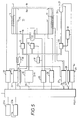
- Figure 5 shows in schematic form a circuit for powering the electrodes of two ion thrusters.
- The spacecraft shown in Figure 3 has thrusters T1, T2 arranged in the same way as for the spacecraft shown schematically in Figure 2 i.e. the thrust acts through the centre of gravity of the spacecraft. It is standard practice in spacecraft to double-up on systems in order to minimize the risk of the spacecraft failing through failure at a single point and, to this end, redundant thrusters T3 and T4, also acting through the centre of gravity of the spacecraft are also provided. The latter thrusters do not come into operation unless one or both of the primary thrusters T1, T2 fails.
- The thrusters T1 to T4 are supplied with propellant from a
tank 1 of propellant via respective valves V1, V2, V3 and V4. Valves V1 and V2 are operated by a switch S1 controlled by a power supply unit PSU1, which also supplies the thrusters T1 and T2 in order to provide, inter alia, a supply to the electrodes of the thrusters. Redundant thrusters T3 and T4 are powered by redundantpower supply unit 2, which also controls switch S3 for controlling the valves V3, V4 of the redundant thrusters. In operation, switching of switch S1 opens only valve V1 or V2 at any one time, in order to power respective thruster T1 or T2. The same applies for redundant thrusters T3 and T4 if they are brought into operation. A conventional spacecraft would have a dedicated power supply unit for each of the four thrusters, greatly increasing the weight of the spacecraft and reducing the weight of the payload. - The thrusters T1 to T4 may be ion thrusters, described in more detail with reference to Figure 5, which relies on an exhaust of accelerated propellant ions to produce thrust, or it may be an arc-jet thruster, or other electrically-powered thruster which relies on a separate power supply unit. The arc-jet is described in more detail with reference to Figure 4, in which case the propellant exhaust velocity is increased by heating of the propellant gas by means of an arc struck between two electrodes. (Unlike ion thrusters, in which more ionisation implies more thrust, ionisation in arc-jets, while necessary for the flow of current which causes the heating of the propellant, should be kept to a minimum because more ionisation requires more power which is a loss and does not produce a proportional increase in thrust). In all cases, the thrusters do not operate unless current flows through the propellant and, while it would be inconvenient to switch the electrodes on and off, since there are large potential differences between them and breakdown of the switching contacts could be caused, it is simply necessary to stop the flow of propellant to the relevant thruster because current is not drawn (except for negligible currents drawn through leakage paths) from the electrodes even when they are energized at their usual potential in the absence of propellant, because the current flows through the ionised propellant. Thus, the electrodes of all the thrusters are energized i.e. charged, when one thruster is brought into operation. The thruster which draws electrical power and produces thrust is the one which receives propellant. It may, however, be found to be desirable to switch on and off supplies to purely resistive loads such as cathode heaters and electro-magnets. Since these would be low voltage supplies, the risk of contact breakdown is minimal in this case.
- The propellant may be Xenon, Argon or Krypton, and may be stored in liquid form, or may be a solid such as Caesium or Mercury which is vapourised when heated.
- Figure 4 shows an arc-jet thruster suitable for use in the configuration of Figure 3.
- The arc-jet is supplied with hydrazine (N₂H₄) from pipe 5 into a
valve 2 which supplies acatalyst bed 3 via an injector 6. The hydrazine dissociates on contact with the catalyst bed into ammonia, nitrogen and hydrogen, and the gases exhaust through the nozzle 4. To increase the velocity of the exhaust gases and hence increase the specific impulse of the thruster, the hydrazine is heated by means of an arc struck between electrodes. To switch the arc-jet on and off, it is simply necessary to switch thevalve 2 on and off, and it is not necessary to switch off the supply to the electrodes since current cannot be drawn from these electrodes if there is no flow of gases between them. Alternative propellants to hydrazine could be used. - Figure 5 shows in more detail the application of the arrangement shown in Figure 3 to the case of ion thrusters. The general configuration of the ion thruster will not be described in detail because it is known and has, for example previously been described in our British patent application No. 2,248,727.
- Briefly, the ion thruster T1 comprises a
discharge chamber 8 to which propellant is supplied from a pipe 9 via avalve 10 and viafurther valves hollow cathode 13 and cathode keeper 14 and electrons flow toannular anode 15 through a magnetic field generated by electro-magnets 16, 17 which cause the electrons to undergo a spiralling path and increase the probability of collision with main propellant flow through opening 18 to provide the main ion beam. The latter passes through the perforated end of thedischarge chamber 8a and through aperforated accelerator grid 19 which is maintained highly negative relative to the discharge chamber to accelerate the ion beam and hence provide the thrust of the thruster. Theaccelerator grid 19 ensures that there is a low divergence to the ion beam, hence preventing electrons from being attracted into the thruster. The resulting positive ion beam emerging from the thruster is neutralised by the further propellant flow throughvalve 33 and hollow cathode 20. An arc is struck between hollow cathode 20 andcathode keeper 21 to generate an electron flow. - The power supply unit PSU1 feeds a number of subsidiary power supply units for the electrodes, as follows: the
negative accelerator grid 22, the beampower supply unit 23, thecathode heater 24, the cathode keeper unitpower supply unit 25, the anodepower supply unit 26, the solenoidpower supply unit 27, theneutraliser cathode heater 28 and the neutraliser keeperpower supply unit 29. - All three propellant flows are controlled by control means 30 - 32 acting on
control valves - The
power supply unit 1 also powers a thruster T2 provided with identical control circuitry to the left of power supply unit PSU1, but only the accelerator gridpower supply unit 22a and beampower supply unit 23a have been shown. - When thruster T1 is operating and it is desired to stop it, it is simply necessary to open contact S5, which shuts
valve 10, and thruster T1 then ceases to draw the heavy beam current because there is no electron flow to theannular anode 15 because there is no propellant in the thruster to be ionised. A small current would nevertheless be drawn from cathode heaterpower supply unit 24 neutraliser cathode heaterpower supply unit 28 and via electro-magnets power supply unit 27 and, for this reason, further switches S4, S6 and S7 are provided to switch these power supplies off as well. Switches S4 to S7 are for convenience ganged together. It will be noticed that the accelerator grid power supply unit, beam power supply unit, anode power supply unit and cathode keeper power supply unit remain connected, because no current will be drawn from them. The same PSU1 also supplies power to thruster T2, but the heaters, the electro-magnets and the propellant valve 10a may be switched off via switches identical to the switches S4 to S7, and this thruster is brought into operation by closure of the switches. Power supply unit PSU1 could be supplied by the solar panels of the spacecraft or by an onboard battery charged by the solar panels. The various voltages provided within PSU1 are conveniently provided by a switched mode power converter. - Of course ion thrusters generally have dedicated power supplies and the single power supply for the two thrusters could provide non-ideal electrode potentials. The power supply therefore includes active control of the thruster by means of control loops corresponding to the three propellant flows described, magnet current adjustment and anode current adjustment. Thus, to get constant thrust, constant beam current from beam
power supply unit 23 must be attained, and this is achieved by monitoring that current through a series resistor with control means 30 to vary the propellant flow by means ofcontrol valve 11 and/or magnet current by adjustingpower supply unit 27. The voltage difference between the anode power supply unit 26 (constant current) and the cathode keeper power supply unit 25 (constant current) is held fixed by adjusting the cathode propellant flow via control means 31 andcontrol valve 12, in order to ensure optimum propellant utilisation. The voltage difference between theneutraliser keeper 21 and the neutraliser cathode 20, caused by the neutraliser keeperpower supply unit 29 in constant current mode, is held constant to maintain fixed neutraliser plasma conditions whilst minimising neutraliser dissipation, thus optimising neutraliser life by controlling the neutraliser cathode propellant flow rate via control means 32 andcontrol valve 33. As an alternative to the use of active control loops, it would be possible to run two thrusters by setting up the power supply output to switch between two (or more) set points according to which thruster is in use. - Further thrusters e.g. T5, T6 for east-west station keeping may also be supplied from power supply unit PSU1, it again being necessary that only one of the thrusters T1, T2, T5, T6 should be powered at any one time. If desired, however, switches S4, S6 and S7 could be omitted and connections to these power supply units made permanent, since the current drawn from these power supplies will only be small in practice.
- As stated above, the invention is also applicable to an arrangement in which the ionised propellant is accelerated by means of a strong magnetic field, and active control of the thruster as described above may again be used, or alternatively set-point operation of more than one thruster is possible from one power supply.
Claims (5)
- A propulsion system for a spacecraft comprising two or more thrusters, each comprising a chamber, means for the supply of gaseous propellant to the chamber, and electrodes arranged in the chamber so that, when the electrodes are energised, gaseous propellant is ionised to maintain a current flow path through the propellant between the electrodes, whereby energy is transferred into the propellant, one power supply capable of energising the electrodes of each of the thrusters simultaneously, and switch means arranged so that only one thruster at a time is supplied with gaseous propellant and can thus draw current through the gaseous propellant to enable thrust to be generated.
- A propulsion system as claimed in claim 1, including valve means controlled by the switch means for opening and closing the supply of propellant gas to the thruster.
- A propulsion system as claimed in claim 1 or claim 2, in which the thrusters are ion thrusters.
- A propulsion system as claimed in claim 1 or claim 2, in which the thrusters are arc-jets.
- A propulsion system as claimed in claim 1 or claim 2, in which the thrusters are plasma engines.
Applications Claiming Priority (2)
| Application Number | Priority Date | Filing Date | Title |
|---|---|---|---|
| GB919127433A GB9127433D0 (en) | 1991-12-27 | 1991-12-27 | Propulsion system for spacecraft |
| GB9127433 | 1991-12-27 |
Publications (2)
| Publication Number | Publication Date |
|---|---|
| EP0550250A1 EP0550250A1 (en) | 1993-07-07 |
| EP0550250B1 true EP0550250B1 (en) | 1995-07-12 |
Family
ID=10706857
Family Applications (1)
| Application Number | Title | Priority Date | Filing Date |
|---|---|---|---|
| EP92311731A Expired - Lifetime EP0550250B1 (en) | 1991-12-27 | 1992-12-23 | Propulsion system for spacecraft |
Country Status (5)
| Country | Link |
|---|---|
| US (1) | US5339623A (en) |
| EP (1) | EP0550250B1 (en) |
| JP (1) | JP3682706B2 (en) |
| DE (1) | DE69203437T2 (en) |
| GB (2) | GB9127433D0 (en) |
Cited By (1)
| Publication number | Priority date | Publication date | Assignee | Title |
|---|---|---|---|---|
| WO2009037196A1 (en) | 2007-09-14 | 2009-03-26 | Thales Electron Devices Gmbh | Drive arrangement in a spacecraft |
Families Citing this family (28)
| Publication number | Priority date | Publication date | Assignee | Title |
|---|---|---|---|---|
| US5400252A (en) * | 1992-12-22 | 1995-03-21 | Space Systems/Loral, Inc. | Spacecraft East/West orbit control during a North or South stationkeeping maneuver |
| US5443231A (en) * | 1993-11-17 | 1995-08-22 | Hughes Aircraft Company | Method and apparatus for a satellite station keeping |
| US6053455A (en) * | 1997-01-27 | 2000-04-25 | Space Systems/Loral, Inc. | Spacecraft attitude control system using low thrust thrusters |
| US5947421A (en) * | 1997-07-09 | 1999-09-07 | Beattie; John R. | Electrostatic propulsion systems and methods |
| US6173565B1 (en) * | 1998-04-09 | 2001-01-16 | Primex Technologies, Inc. | Three axis pulsed plasma thruster with angled cathode and anode strip lines |
| US6031334A (en) * | 1998-06-17 | 2000-02-29 | Primex Technologies, Inc. | Method and apparatus for selectively distributing power in a thruster system |
| EP1021073A1 (en) * | 1999-01-18 | 2000-07-19 | Matra Marconi Space France S.A. | An ion accelerator |
| US6835062B2 (en) * | 2001-12-14 | 2004-12-28 | Suntec Industries Incorporated | Fuel oil supply circuit for an oil burner having a solenoid valve in parallel circuit with diaphragm valve for controlling oil flow at start up |
| US6948305B2 (en) * | 2003-07-09 | 2005-09-27 | The Boeing Company | Method and apparatus for balancing the emission current of neutralizers in ion thruster arrays |
| US7808353B1 (en) | 2006-08-23 | 2010-10-05 | The United States Of America As Represented By The Administrator Of The National Aeronautics And Space Administration | Coil system for plasmoid thruster |
| US8453426B2 (en) * | 2009-04-06 | 2013-06-04 | Raytheon Company | Current controlled field emission thruster |
| KR101135651B1 (en) * | 2009-12-11 | 2012-04-13 | 한국항공우주연구원 | Valve control device for safe operating of propulsion valve |
| FR2963811B1 (en) * | 2010-08-12 | 2012-08-31 | Snecma | ELECTRIC PROPELLER, METHOD FOR STOPPING AN ELECTRIC MOTOR INCLUDED IN SUCH A PROPELLER AND SATELLITE COMPRISING SUCH A PROPELLER |
| FR2979956B1 (en) * | 2011-09-09 | 2013-09-27 | Snecma | PLASMA STATIONARY POWER PROPULSION PROPULSION SYSTEM |
| US20130327015A1 (en) * | 2012-06-12 | 2013-12-12 | Pamela Pollet | Dual use hydrazine propulsion thruster system |
| FR2997462B1 (en) * | 2012-10-30 | 2018-09-14 | Safran Aircraft Engines | SUPPLYING AN ION PROPELLANT IN PROPULSIVE GAS |
| US9181934B2 (en) * | 2012-11-21 | 2015-11-10 | The Boeing Company | Rotary switch assembly for ion propulsion system |
| FR3002594B1 (en) * | 2013-02-26 | 2016-09-30 | Snecma | SPIRAL PROPULSION MODULE WITH ELECTRIC PROPULSION AND CHEMICAL WITH SOLID PROPERGOL |
| US11325727B2 (en) | 2013-08-27 | 2022-05-10 | The Regents Of The University Of Michigan | Converging/diverging magnetic nozzle |
| WO2015031450A1 (en) * | 2013-08-27 | 2015-03-05 | The Regents Of The University Of Michigan | Electrodeless plasma thruster |
| ES2498716B1 (en) * | 2014-08-19 | 2015-07-09 | Antonio SÁNCHEZ TORRES | Space propulsion system by electrostatic modification |
| FR3032427B1 (en) * | 2015-02-10 | 2017-03-10 | Airbus Defence & Space Sas | SATELLITE HAVING ELECTRICAL PROPULSION MEANS, METHOD OF POSTING SUCH A SATELLITE AND METHOD FOR MAINTAINING SATELLITE |
| FR3037928B1 (en) * | 2015-06-26 | 2017-07-14 | Thales Sa | SYSTEM FOR CONTROLLING SEVERAL ELECTRICAL PROPELLERS FOR SATELLITE AND ELECTRICAL PROPULSION DEVICE COMPRISING SUCH A CONTROL SYSTEM |
| US11117685B2 (en) * | 2016-06-28 | 2021-09-14 | Mitsubishi Electric Corporation | Artificial satellite and thrust balance adjustment method |
| EP3560298A4 (en) | 2016-12-21 | 2020-08-12 | Phase Four, Inc. | PLASMA PRODUCTION AND CONTROL DEVICE |
| US20190107103A1 (en) | 2017-10-09 | 2019-04-11 | Phase Four, Inc. | Electrothermal radio frequency thruster and components |
| US12195205B2 (en) | 2019-09-04 | 2025-01-14 | Phase Four, Inc. | Propellant injector system for plasma production devices and thrusters |
| FI129831B (en) * | 2020-04-02 | 2022-09-15 | Aurora Propulsion Tech Oy | SHOOTING UNIT |
Family Cites Families (10)
| Publication number | Priority date | Publication date | Assignee | Title |
|---|---|---|---|---|
| FR1366930A (en) * | 1963-06-06 | 1964-07-17 | Snecma | Electron bombardment ion source with large ring-shaped extraction surface usable for ion propulsion |
| DE1248374C2 (en) * | 1964-06-10 | 1968-03-07 | Hughes Aircraft Co | Propulsion device with a jet engine |
| US3465522A (en) * | 1965-03-09 | 1969-09-09 | Hughes Aircraft Co | Ion rocket |
| US3591967A (en) * | 1968-09-05 | 1971-07-13 | Nasa | Feed system for an ion thruster |
| US4397147A (en) * | 1980-09-22 | 1983-08-09 | The United States Of America As Represented By The Secretary Of The Air Force | Power circuit utilizing self excited Hall effect switch means |
| US4862032A (en) * | 1986-10-20 | 1989-08-29 | Kaufman Harold R | End-Hall ion source |
| US4805400A (en) * | 1987-04-27 | 1989-02-21 | Olin Corporation | Non-erosive arcjet starting control system and method |
| US4869929A (en) * | 1987-11-10 | 1989-09-26 | Air Products And Chemicals, Inc. | Process for preparing sic protective films on metallic or metal impregnated substrates |
| US5263666A (en) * | 1988-12-16 | 1993-11-23 | General Electric Co. | Spacecraft with increased stationkeeping fuel load |
| DE69026337T2 (en) * | 1989-10-31 | 1996-08-14 | Nippon Electric Co | Ion drive for space flights |
-
1991
- 1991-12-27 GB GB919127433A patent/GB9127433D0/en active Pending
-
1992
- 1992-11-27 GB GB9224846A patent/GB2262777B/en not_active Expired - Lifetime
- 1992-12-21 JP JP34029592A patent/JP3682706B2/en not_active Expired - Lifetime
- 1992-12-22 US US07/993,769 patent/US5339623A/en not_active Expired - Lifetime
- 1992-12-23 EP EP92311731A patent/EP0550250B1/en not_active Expired - Lifetime
- 1992-12-23 DE DE69203437T patent/DE69203437T2/en not_active Expired - Lifetime
Cited By (1)
| Publication number | Priority date | Publication date | Assignee | Title |
|---|---|---|---|---|
| WO2009037196A1 (en) | 2007-09-14 | 2009-03-26 | Thales Electron Devices Gmbh | Drive arrangement in a spacecraft |
Also Published As
| Publication number | Publication date |
|---|---|
| DE69203437T2 (en) | 1995-12-14 |
| GB2262777A (en) | 1993-06-30 |
| DE69203437D1 (en) | 1995-08-17 |
| JP3682706B2 (en) | 2005-08-10 |
| US5339623A (en) | 1994-08-23 |
| JPH05248347A (en) | 1993-09-24 |
| GB2262777B (en) | 1994-11-09 |
| GB9224846D0 (en) | 1993-01-13 |
| GB9127433D0 (en) | 1992-02-19 |
| EP0550250A1 (en) | 1993-07-07 |
Similar Documents
| Publication | Publication Date | Title |
|---|---|---|
| US5339623A (en) | Singly fueled multiple thrusters simultaneously energized by a common power supply | |
| US5947421A (en) | Electrostatic propulsion systems and methods | |
| US4825646A (en) | Spacecraft with modulated thrust electrostatic ion thruster and associated method | |
| US4838021A (en) | Electrostatic ion thruster with improved thrust modulation | |
| US6640535B2 (en) | Linear gridless ion thruster | |
| JP5391490B2 (en) | Drive units in spacecraft | |
| US7395656B2 (en) | Dual mode hybrid electric thruster | |
| CN115163439A (en) | Low-power hollow cathode propulsion system | |
| US6031334A (en) | Method and apparatus for selectively distributing power in a thruster system | |
| US20220205437A1 (en) | Method for controlling an ion thruster, and ion thruster system | |
| JP6472320B2 (en) | Satellite | |
| Beattie et al. | Xenon ion sources for space applications | |
| Koizumi et al. | Development of the miniature ion propulsion system for 50 kg small spacecraft | |
| WO1999028624A1 (en) | Cathode current sharing apparatus and method therefor | |
| BEATTIE et al. | Electric propulsion-A national capability | |
| Fearn | Ion propulsion—a technology for improving the cost-effectiveness of large communications satellites | |
| BEATTIE et al. | High-current plasma contactor neutralizer system | |
| Myers et al. | Small satellite electric propulsion options | |
| SOVEY et al. | The evolutionary development of high specific impulse electric thruster technology | |
| Godwin et al. | Electric Propulsion for Orbital Transfer | |
| FINKE et al. | Current technology in ion and electrothermal propulsion | |
| Lugtu | Impact of ion propulsion on performance, design, testing and operation of a geosynchronous spacecraft | |
| Holdaway | Satellite Orbit Control Incorporating Attitude Control Techniques | |
| RAWLIN | Advanced ion propulsion for space exploration | |
| Ashby et al. | Electric propulsion in space |
Legal Events
| Date | Code | Title | Description |
|---|---|---|---|
| PUAI | Public reference made under article 153(3) epc to a published international application that has entered the european phase |
Free format text: ORIGINAL CODE: 0009012 |
|
| AK | Designated contracting states |
Kind code of ref document: A1 Designated state(s): DE FR IT |
|
| 17P | Request for examination filed |
Effective date: 19930628 |
|
| 17Q | First examination report despatched |
Effective date: 19941115 |
|
| GRAA | (expected) grant |
Free format text: ORIGINAL CODE: 0009210 |
|
| AK | Designated contracting states |
Kind code of ref document: B1 Designated state(s): DE FR IT |
|
| ITF | It: translation for a ep patent filed | ||
| REF | Corresponds to: |
Ref document number: 69203437 Country of ref document: DE Date of ref document: 19950817 |
|
| ET | Fr: translation filed | ||
| PLBE | No opposition filed within time limit |
Free format text: ORIGINAL CODE: 0009261 |
|
| STAA | Information on the status of an ep patent application or granted ep patent |
Free format text: STATUS: NO OPPOSITION FILED WITHIN TIME LIMIT |
|
| 26N | No opposition filed | ||
| REG | Reference to a national code |
Ref country code: FR Ref legal event code: CD |
|
| PGFP | Annual fee paid to national office [announced via postgrant information from national office to epo] |
Ref country code: FR Payment date: 20120105 Year of fee payment: 20 |
|
| PGFP | Annual fee paid to national office [announced via postgrant information from national office to epo] |
Ref country code: DE Payment date: 20111222 Year of fee payment: 20 |
|
| PGFP | Annual fee paid to national office [announced via postgrant information from national office to epo] |
Ref country code: IT Payment date: 20111227 Year of fee payment: 20 |
|
| REG | Reference to a national code |
Ref country code: DE Ref legal event code: R071 Ref document number: 69203437 Country of ref document: DE |
|
| REG | Reference to a national code |
Ref country code: DE Ref legal event code: R071 Ref document number: 69203437 Country of ref document: DE |