EP0550238B1 - A double action pistol with improved firing mechanism - Google Patents
A double action pistol with improved firing mechanism Download PDFInfo
- Publication number
- EP0550238B1 EP0550238B1 EP92311682A EP92311682A EP0550238B1 EP 0550238 B1 EP0550238 B1 EP 0550238B1 EP 92311682 A EP92311682 A EP 92311682A EP 92311682 A EP92311682 A EP 92311682A EP 0550238 B1 EP0550238 B1 EP 0550238B1
- Authority
- EP
- European Patent Office
- Prior art keywords
- hammer
- sear
- trigger
- pistol
- members
- Prior art date
- Legal status (The legal status is an assumption and is not a legal conclusion. Google has not performed a legal analysis and makes no representation as to the accuracy of the status listed.)
- Expired - Lifetime
Links
- 238000010304 firing Methods 0.000 title claims abstract description 34
- 230000007246 mechanism Effects 0.000 title claims abstract description 23
- 230000006835 compression Effects 0.000 claims description 12
- 238000007906 compression Methods 0.000 claims description 12
- 230000004913 activation Effects 0.000 claims description 4
- 230000008878 coupling Effects 0.000 description 4
- 238000010168 coupling process Methods 0.000 description 4
- 238000005859 coupling reaction Methods 0.000 description 4
- 230000000994 depressogenic effect Effects 0.000 description 2
- 239000000567 combustion gas Substances 0.000 description 1
- 239000007789 gas Substances 0.000 description 1
- 239000003380 propellant Substances 0.000 description 1
- 230000035939 shock Effects 0.000 description 1
Images


Classifications
-
- F—MECHANICAL ENGINEERING; LIGHTING; HEATING; WEAPONS; BLASTING
- F41—WEAPONS
- F41A—FUNCTIONAL FEATURES OR DETAILS COMMON TO BOTH SMALLARMS AND ORDNANCE, e.g. CANNONS; MOUNTINGS FOR SMALLARMS OR ORDNANCE
- F41A17/00—Safety arrangements, e.g. safeties
- F41A17/74—Hammer safeties, i.e. means for preventing the hammer from hitting the cartridge or the firing pin
- F41A17/82—Hammer safeties, i.e. means for preventing the hammer from hitting the cartridge or the firing pin trigger-operated, i.e. the movement of the trigger bringing a hammer safety into inoperative position during firing
-
- F—MECHANICAL ENGINEERING; LIGHTING; HEATING; WEAPONS; BLASTING
- F41—WEAPONS
- F41A—FUNCTIONAL FEATURES OR DETAILS COMMON TO BOTH SMALLARMS AND ORDNANCE, e.g. CANNONS; MOUNTINGS FOR SMALLARMS OR ORDNANCE
- F41A17/00—Safety arrangements, e.g. safeties
- F41A17/74—Hammer safeties, i.e. means for preventing the hammer from hitting the cartridge or the firing pin
-
- F—MECHANICAL ENGINEERING; LIGHTING; HEATING; WEAPONS; BLASTING
- F41—WEAPONS
- F41A—FUNCTIONAL FEATURES OR DETAILS COMMON TO BOTH SMALLARMS AND ORDNANCE, e.g. CANNONS; MOUNTINGS FOR SMALLARMS OR ORDNANCE
- F41A19/00—Firing or trigger mechanisms; Cocking mechanisms
- F41A19/06—Mechanical firing mechanisms, e.g. counterrecoil firing, recoil actuated firing mechanisms
- F41A19/14—Hammers, i.e. pivotably-mounted striker elements; Hammer mountings
-
- F—MECHANICAL ENGINEERING; LIGHTING; HEATING; WEAPONS; BLASTING
- F41—WEAPONS
- F41A—FUNCTIONAL FEATURES OR DETAILS COMMON TO BOTH SMALLARMS AND ORDNANCE, e.g. CANNONS; MOUNTINGS FOR SMALLARMS OR ORDNANCE
- F41A19/00—Firing or trigger mechanisms; Cocking mechanisms
- F41A19/06—Mechanical firing mechanisms, e.g. counterrecoil firing, recoil actuated firing mechanisms
- F41A19/42—Mechanical firing mechanisms, e.g. counterrecoil firing, recoil actuated firing mechanisms having at least one hammer
- F41A19/43—Mechanical firing mechanisms, e.g. counterrecoil firing, recoil actuated firing mechanisms having at least one hammer in bolt-action guns
- F41A19/44—Sear arrangements therefor
- F41A19/45—Sear arrangements therefor for catching the hammer after each shot, i.e. in single-shot or semi-automatic firing mode
-
- F—MECHANICAL ENGINEERING; LIGHTING; HEATING; WEAPONS; BLASTING
- F41—WEAPONS
- F41A—FUNCTIONAL FEATURES OR DETAILS COMMON TO BOTH SMALLARMS AND ORDNANCE, e.g. CANNONS; MOUNTINGS FOR SMALLARMS OR ORDNANCE
- F41A19/00—Firing or trigger mechanisms; Cocking mechanisms
- F41A19/06—Mechanical firing mechanisms, e.g. counterrecoil firing, recoil actuated firing mechanisms
- F41A19/42—Mechanical firing mechanisms, e.g. counterrecoil firing, recoil actuated firing mechanisms having at least one hammer
- F41A19/43—Mechanical firing mechanisms, e.g. counterrecoil firing, recoil actuated firing mechanisms having at least one hammer in bolt-action guns
- F41A19/47—Cocking mechanisms
-
- F—MECHANICAL ENGINEERING; LIGHTING; HEATING; WEAPONS; BLASTING
- F41—WEAPONS
- F41A—FUNCTIONAL FEATURES OR DETAILS COMMON TO BOTH SMALLARMS AND ORDNANCE, e.g. CANNONS; MOUNTINGS FOR SMALLARMS OR ORDNANCE
- F41A19/00—Firing or trigger mechanisms; Cocking mechanisms
- F41A19/06—Mechanical firing mechanisms, e.g. counterrecoil firing, recoil actuated firing mechanisms
- F41A19/42—Mechanical firing mechanisms, e.g. counterrecoil firing, recoil actuated firing mechanisms having at least one hammer
- F41A19/43—Mechanical firing mechanisms, e.g. counterrecoil firing, recoil actuated firing mechanisms having at least one hammer in bolt-action guns
- F41A19/47—Cocking mechanisms
- F41A19/48—Double-action mechanisms, i.e. the cocking being effected during the first part of the trigger pull movement
Definitions
- the present invention relates to a pistol and more specifically to a double action pistol with a decocking mechanism.
- the subject-matter of the preamble of claim 1 is well known in practice.
- a double action pistol comprises among others a barrel with a breech at the rear end; a slide also known as breech block and bearing a firing pin; a trigger with associated trigger bar, sear and interruptor; a spring-loaded hammer; a magazine within a magazine chamber and a safety mechanism.
- the slide slides back and forth between an advanced, firing position and a rear, cocked position.
- the forward movement is brought about by the expansion of so-called recoil springs which occurs when the trigger is pulled, and during this movement the slide strips a cartridge from the magazine and inserts it into the breech whereupon the hammer strikes the firing pin and the cartridge is fired.
- the propellant gas pressure pushes the slide rearwards whereby the recoil springs are compressed, the hammer is cocked and the pistol is ready for another firing round.
- the magazine holds a limited number of ammunition rounds, say fifteen, and when in the course of operation the magazine is emptied it has to be replaced by a new, loaded one.
- the hammer When the pistol has to be cocked manually by pulling the slide rearwards, the hammer is eccentrically tilted to the rear, thereby compressing the spring with which it is associated and thus creating a bias that upon release urges the hammer to swing forward and strike the firing pin inside the slide. As long as the trigger is not pulled, the sear locks the hammer in the cocked position. When the trigger is pulled, the rearward moving trigger bar pushes the sear out of engagement with the hammer whereupon the latter is released and strikes the firing pin.
- a double action pistol having a trigger with associated trigger bar, sear and interruptor, which trigger is of the kind which when pulled goes through first and second activation phases; a slide; a hammer and hammer associated compression spring which, when compressed, urges the hammer to strike the rear of the firing pin within the slide; and a decocking mechanism; characterized by:
- the forward position of the second hammer member can be reached either in consequence of a second-phase trigger pull which results in firing of the pistol, or in consequence of decocking which does not result in firing.
- the decocking mechanism When in a double action pistol according to the invention the decocking mechanism is operated, only the second, striking hammer member swings forward while the first, power transmitting hammer member remains in the cocked state. Consequently, for returning the second, striking hammer member from the fore to the reclining position, it is not necessary to recompress the hammer-associated compression spring which remains compressed even though the second, striking hammer member was decocked. As a result, during the second phase of a trigger pull, only a very small force is required for returning the second hammer member into the reclined position. Accordingly, in a pistol according to the invention the force required for triggering off a shot corresponds essentially to that required for the performance of the first phase of the trigger pull. Thus, as compared to state of the art double action pistols, the total force required for triggering off a shot in a double action pistol according to the invention is of the order of 2-3 kg as compared to 6-10 kg in state of the art pistols.
- the double-action pistol according to the invention here shown has a housing 1 fitted with a slide 2 carrying a firing pin (not shown) and a safety catch 3 keyed on an axle 4 and fitted with an actuation lever 5.
- Axle 4 is mounted within a base in the slide and is rotatable therein for shifting between safe and firing positions.
- the internal end portion of axle 4 merges into an eccenter 6 adapted for cooperation with the head portion of an upward biased pin 7 (the biasing means not being shown) which, when lever 5 is shifted into the safe position, is depressed by eccenter 6 and when lever 5 is shifted into the firing position, moves up as the result of its upward bias.
- the firing mechanism in a pistol comprises a split hammer assembly 10 and a split sear assembly 11 which will now be described with reference to Figs. 5 and 6.
- the split hammer assembly 10 comprises a first, power-transmitting hammer member 12 and a second, striking hammer member 13.
- the hammer members 12 and 13 comprise registering holes 14 and 15 receiving an axle 16 journalled in body 1.
- the power-transmitting hammer member 12 comprises a further hole 17 which serves for linking to a hammer rod.
- the upper surface 18 of the first hammer member 12 serves for cooperation with the second hammer member 13 and a tooth 19 serves for cooperation with the sear.
- a hammer rod 20 is pivotally linked to the first, power-transmitting hammer member 12 by means of a pin 21 engaging hole 17.
- Hammer rod 20 comprises an upper, arcuate portion 22 and a lower, straight cylindrical portion 23 with a shoulder 24 being formed between the two portions.
- Hammer rod portion 23 penetrates through the bottom of a cup 25 connected to the magazine portion of housing 1.
- a helical hammer spring 26 is coiled on the straight hammer rod portion 23 with its upper end bearing on shoulder 24 and the lower end being received in and bearing on the bottom of cup 25.
- the second, striking hammer member 13 has an upper striking portion 27 and a lower, arm portion 28 forming between them a shoulder 29.
- the top side of the striking part 27 is knurled to provide for better grip in case of manual actuation and the front side 30 serves for striking.
- the lower, arm portion of the second hammer member 13 has an integral bracket 31 comprising a hole 32 serving for linking to the interruptor, and a tooth 33.
- the sear assembly 11 comprises a first sear member 35 and a second sear member 36 having registering holes 37 and 38 by which they are rotatably mounted on an axle 39 journalled in housing 1, each with an anti-clockwise bias provided by helical springs 40 and 41, respectively.
- the first sear member 35 has an upper, rearward protecting bracket 42 for cooperation with tooth 19 of the first hammer member 12, and a lower, forward protecting bracket 43 for cooperation with the trigger mechanism.
- the second sear member 36 comprises a rearward protecting bracket 45 for cooperation with tooth 33 of the second hammer member 13, a lateral bracket 46 with a flat slanting bottom adapted for cooperation with the upper matching surface of shoulder 44 of the first sear member 35, an upper arm 47 for cooperation with pin 7 of the safety catch 3 and a lower arm 48 for cooperation with the trigger mechanism.
- the trigger mechanism comprises a trigger 50 pivoted to the housing at 51 with a bias into the forward, release position by means of a helical spring 52.
- a trigger bar 53 is pivotally linked to trigger 50 at 54.
- Trigger bar 53 comprises a shank 55 and a frame having two longitudinal frame members 56 extending each along one of the side walls of the magazine chamber, and a terminal lateral frame member 57 having a cavity 58.
- Trigger bar 53 is associated with a trigger plunger 59 reciprocable on a pin 60 mounted on housing 1 and loaded with a helical spring 61 which bears on a collar of pin 60 and provides an upward bias.
- Frame members 56 comprise each an upward projection 62 for cooperation with slide 2.
- frame members 56 have each a shoulder 63 for cooperation with matching shoulders 64 of an interruptor 65 linked to the second hammer member 13 by means of a pin 66 engaging hole 32 of bracket 31 of the second hammer member 13 and a registering hole 67 of the interruptor.
- Interruptor 65 is hook-shaped having a downward projecting leg portion 68 which is accommodated within cavity 58 of the trigger bar frame member 57.
- Fig. 3 Attention is now directed to Fig. 3 for the description of the decocking operation.
- lever 5 of the safety catch 3 is depressed, the apex of eccenter 6 of axle 4 depresses pin 7 which in turn depresses arm 47 of the second sear member 36 whereby the latter is turned anti-clockwise and projection 45 thereof disengages tooth 33 of the second hammer member 13.
- trigger spring 52 in combination with the biasing action of the trigger plunger 59, the trigger 50 is automatically pulled forward dragging with it trigger bar 53 and interruptor 65 which in turn, by its eccentric link at 66 to bracket 31 of the second hammer member 13, causes the latter to swing anti-clockwise into the upright, decocked position of Fig. 3.
- the second hammer member 13 can swing from the reclined position forward independent of the first hammer member 12.
- the second hammer member serves as prime mover in the course of being reclined, it drags with it the first hammer member 12.
- the first hammer member 12 acts as prime mover in consequence of the action of the hammer spring 26, it pushes with it the second hammer member 13.
- the coupling surfaces of the two sear members 36 and 35 they remain coupled during cocking and firing, but the second sear member 36 can swing to the rear during decocking independent of the first sear member 35.
- lever 5 of the safety catch 3 has to be shifted into the firing position whereby pin 7 is retracted in consequence of its upward bias and the second sear member 36 is free to swing clockwise by the action of its biasing spring 42 which enables the spring-biased plunger 59 to push the trigger bar 53 back into engagement with the interruptor 65.
- the interruptor 65 pushes the second hammer member 13 back into the reclined position of Fig. 2 with the bracket 45 of the second sear member 36 snapping back into engagement with tooth 33 of the second hammer member 13. In that position both the first and second hammer members 12 and 13 and the first and second sear members 35 and 36 are again coupled.
- the trigger bar 53 keeps moving backward shoulders 63 thereof engage shoulders 64 of the interruptor 65 whereby the second hammer member 13 is pushed into the reclined position of Fig. 4.
- the two coupled sear members 35 and 36 are caused to swing anti-clockwise clearing teeth 19 and 33 of the first and second hammer members 12 and 13, respectively.
- the hammer spring 26 is free to expand and forcibly drives the hammer rod 20 upwards which, in consequence of its eccentric linkage to the first sear member 12, causes the latter and the second hammer member 13 coupled therewith to forcibly swing anti-clockwise until the striking surface 30 of the second hammer member 13 strikes the firing pin whereby the pistol is fired.
- the slide 2 is recoiled by the expanding combustion gases and the pistol can be fired again or, alternatively, be decocked as may be desired.
Landscapes
- Engineering & Computer Science (AREA)
- General Engineering & Computer Science (AREA)
- Fish Paste Products (AREA)
- Percussion Or Vibration Massage (AREA)
- Meat, Egg Or Seafood Products (AREA)
- Toys (AREA)
- Finger-Pressure Massage (AREA)
Abstract
Description
- The present invention relates to a pistol and more specifically to a double action pistol with a decocking mechanism. The subject-matter of the preamble of claim 1 is well known in practice.
- A double action pistol comprises among others a barrel with a breech at the rear end; a slide also known as breech block and bearing a firing pin; a trigger with associated trigger bar, sear and interruptor; a spring-loaded hammer; a magazine within a magazine chamber and a safety mechanism. During operation the slide slides back and forth between an advanced, firing position and a rear, cocked position. The forward movement is brought about by the expansion of so-called recoil springs which occurs when the trigger is pulled, and during this movement the slide strips a cartridge from the magazine and inserts it into the breech whereupon the hammer strikes the firing pin and the cartridge is fired. Upon firing, the propellant gas pressure pushes the slide rearwards whereby the recoil springs are compressed, the hammer is cocked and the pistol is ready for another firing round.
- The magazine holds a limited number of ammunition rounds, say fifteen, and when in the course of operation the magazine is emptied it has to be replaced by a new, loaded one.
- When the pistol has to be cocked manually by pulling the slide rearwards, the hammer is eccentrically tilted to the rear, thereby compressing the spring with which it is associated and thus creating a bias that upon release urges the hammer to swing forward and strike the firing pin inside the slide. As long as the trigger is not pulled, the sear locks the hammer in the cocked position. When the trigger is pulled, the rearward moving trigger bar pushes the sear out of engagement with the hammer whereupon the latter is released and strikes the firing pin.
- In practice, it very often happens that in anticipation of a pistol shooting event a combatant cocks his pistol and switches the safety catch from the safe to the firing position. This, however, creates a dangerous situation in that any accidental shock or impact may release the hammer and cause the pistol to be fired. It is possible to cope with such a situation by manually decocking the hammer in guiding it gently into the forward position without allowing it to strike the firing pin. When now the trigger is pulled, the trigger bar will in a first phase, in collaboration with the sear and interruptor, recock the hammer. By further pulling the trigger it will, in a second phase, bring about the release of the hammer so that the latter may forcibly strike the firing pin, thereby triggering off the firing and subsequent recoiling operation.
- In order to avoid the need for manual decocking, some double action pistols are provided with mechanical decocking mechanisms.
- Decocking of a state of the art double action type pistol brings about the expansion of the compression spring associated with the hammer with the consequence that during the trigger pull phase at which the hammer is recocked, it is necessary to exert sufficient force for the recompression of the compression spring associated with the hammer. Depending on the type of pistol, a complete trigger pull may require the exertion of a force of the order of 6-10 kg, of which the first phase trigger pull accounts only for about 2-3 kg. Thus, where in a manually cocked conventional double-action pistol the hammer is decocked, the performance of the first shot requires the exertion of a substantial force. Apart from the intrinsic inconvenience, such exertion of force may and usually does cause inaccurate firing which, when bearing in mind that the first shot is very often the most critical, may have fatal consequences.
- It is thus the object of the present invention to provide a double action pistol with a decocking mechanism as known per se, having an improved trigger mechanism by which the force that has to be exerted for firing the pistol from a decocked state is significantly smaller than with state of the art double action pistols.
- In accordance with the present invention there is provided a double action pistol having a trigger with associated trigger bar, sear and interruptor, which trigger is of the kind which when pulled goes through first and second activation phases; a slide; a hammer and hammer associated compression spring which, when compressed, urges the hammer to strike the rear of the firing pin within the slide; and a decocking mechanism; characterized by:
- i) a split hammer assembly comprising a first, power transmitting hammer member linked with the said compression spring and eccentrically swingable between a reclined, cocked position in which said compression spring is compressed and a forward position in which said compression spring is expanded; and a second, striking hammer member swingable between a reclined, cocked position and a forward position; said first and second hammer members being detachably coupled;
- ii) a split sear assembly comprising a first sear member associated with said first hammer member, capable of reciprocating between an engaging position in which it engages said first hammer member and a disengaging position and biased into the engaging position; and a second sear member associated with said decocking mechanism and said second hammer member, reciprocable between an engaging position in which it engages said second hammer member and a disengaging position and biased into the engaging position; said first and second sear members being detachably coupled whereby when the trigger is pulled into said second activation phase both sear members are simultaneously shifted into the disengaging position.
- The forward position of the second hammer member can be reached either in consequence of a second-phase trigger pull which results in firing of the pistol, or in consequence of decocking which does not result in firing.
- When in a double action pistol according to the invention the decocking mechanism is operated, only the second, striking hammer member swings forward while the first, power transmitting hammer member remains in the cocked state. Consequently, for returning the second, striking hammer member from the fore to the reclining position, it is not necessary to recompress the hammer-associated compression spring which remains compressed even though the second, striking hammer member was decocked. As a result, during the second phase of a trigger pull, only a very small force is required for returning the second hammer member into the reclined position. Accordingly, in a pistol according to the invention the force required for triggering off a shot corresponds essentially to that required for the performance of the first phase of the trigger pull. Thus, as compared to state of the art double action pistols, the total force required for triggering off a shot in a double action pistol according to the invention is of the order of 2-3 kg as compared to 6-10 kg in state of the art pistols.
- For better understanding, the invention will now be described, by way of example only, with reference to the annexed drawings without being limited thereto. In the drawings:
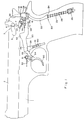
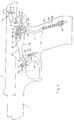
- Fig. 1 is an elevation, partly broken open, of a pistol according to the invention showing the firing mechanism according to the present invention in the non-cocked state;
- Fig. 2 is an elevation, partly broken open, of a pistol according to the invention showing the firing mechanism according to the present invention in the cocked state;
- Fig. 3 is an elevational view of the firing mechanism in the pistol of Figs. 1 and 2 in the decocked state, drawn to a larger scale and also showing the safety catch;
- Fig. 4 is an elevational view of the firing mechanism in the pistol of Figs. 1 and 2 in the fully cocked pre-firing state;
- Figs. 5 and 6 are isometric views of the sear and hammer members according to the present invention; and
- Fig. 7 shows isometrically the trigger bar and interruptor of the firing mechanism of Figs. 3 and 4.
- The double-action pistol according to the invention here shown has a housing 1 fitted with a
slide 2 carrying a firing pin (not shown) and asafety catch 3 keyed on an axle 4 and fitted with anactuation lever 5. Axle 4 is mounted within a base in the slide and is rotatable therein for shifting between safe and firing positions. The internal end portion of axle 4 merges into aneccenter 6 adapted for cooperation with the head portion of an upward biased pin 7 (the biasing means not being shown) which, whenlever 5 is shifted into the safe position, is depressed by eccenter 6 and whenlever 5 is shifted into the firing position, moves up as the result of its upward bias. - The firing mechanism in a pistol according to the invention comprises a
split hammer assembly 10 and asplit sear assembly 11 which will now be described with reference to Figs. 5 and 6. As shown, thesplit hammer assembly 10 comprises a first, power-transmittinghammer member 12 and a second,striking hammer member 13. Thehammer members holes axle 16 journalled in body 1. The power-transmittinghammer member 12 comprises afurther hole 17 which serves for linking to a hammer rod. Theupper surface 18 of thefirst hammer member 12 serves for cooperation with thesecond hammer member 13 and atooth 19 serves for cooperation with the sear. - A
hammer rod 20 is pivotally linked to the first, power-transmittinghammer member 12 by means of apin 21 engaginghole 17. Hammerrod 20 comprises an upper,arcuate portion 22 and a lower, straightcylindrical portion 23 with ashoulder 24 being formed between the two portions.Hammer rod portion 23 penetrates through the bottom of acup 25 connected to the magazine portion of housing 1. Ahelical hammer spring 26 is coiled on the straighthammer rod portion 23 with its upper end bearing onshoulder 24 and the lower end being received in and bearing on the bottom ofcup 25. - The second,
striking hammer member 13 has an upperstriking portion 27 and a lower,arm portion 28 forming between them ashoulder 29. The top side of thestriking part 27 is knurled to provide for better grip in case of manual actuation and thefront side 30 serves for striking. - The lower, arm portion of the
second hammer member 13 has anintegral bracket 31 comprising ahole 32 serving for linking to the interruptor, and atooth 33. - The
sear assembly 11 comprises afirst sear member 35 and asecond sear member 36 having registeringholes axle 39 journalled in housing 1, each with an anti-clockwise bias provided byhelical springs first sear member 35 has an upper, rearward protectingbracket 42 for cooperation withtooth 19 of thefirst hammer member 12, and a lower, forward protectingbracket 43 for cooperation with the trigger mechanism. There is further provided ashoulder 44 for cooperation with thesecond sear member 36. - The
second sear member 36 comprises a rearward protectingbracket 45 for cooperation withtooth 33 of thesecond hammer member 13, alateral bracket 46 with a flat slanting bottom adapted for cooperation with the upper matching surface ofshoulder 44 of thefirst sear member 35, anupper arm 47 for cooperation withpin 7 of thesafety catch 3 and alower arm 48 for cooperation with the trigger mechanism. - Attention is now directed to Figs. 1 to 4 for the description of the trigger mechanism. As shown, the trigger mechanism comprises a
trigger 50 pivoted to the housing at 51 with a bias into the forward, release position by means of ahelical spring 52. Atrigger bar 53 is pivotally linked totrigger 50 at 54.Trigger bar 53 comprises ashank 55 and a frame having twolongitudinal frame members 56 extending each along one of the side walls of the magazine chamber, and a terminallateral frame member 57 having acavity 58.Trigger bar 53 is associated with atrigger plunger 59 reciprocable on apin 60 mounted on housing 1 and loaded with ahelical spring 61 which bears on a collar ofpin 60 and provides an upward bias.Frame members 56 comprise each anupward projection 62 for cooperation withslide 2. Near their end portions framemembers 56 have each ashoulder 63 for cooperation with matchingshoulders 64 of aninterruptor 65 linked to thesecond hammer member 13 by means of apin 66 engaginghole 32 ofbracket 31 of thesecond hammer member 13 and a registeringhole 67 of the interruptor. -
Interruptor 65 is hook-shaped having a downward projectingleg portion 68 which is accommodated withincavity 58 of the triggerbar frame member 57. - The operation of the pistol according to the invention as here described is as follows:
- In the position shown in Fig. 1 the pistol is completely inactive. In this position the two
hammer members shoulder 29 bears on theupper surface 18 of thefirst hammer member 12. Likewise, the first and secondsear members bracket 46 of the second sear member bears on the matching surface ofshoulder 44 of the first sear member. When now slide 2 is pulled manually to the rear into the position shown in Fig. 2, the two coupledhammer members sear members teeth second hammer members hammer rod 20 and the secondsear member 12, the hammer rod is pushed down as a result of the rearward swing of thefirst hammer member 12, wherebycompression hammer spring 26 is compressed and the pistol is fully cocked. At this stage the user can choose between firing the pistol or decocking it. - Attention is now directed to Fig. 3 for the description of the decocking operation. As shown, when
lever 5 of thesafety catch 3, is depressed, the apex ofeccenter 6 of axle 4 depressespin 7 which in turn depressesarm 47 of the secondsear member 36 whereby the latter is turned anti-clockwise andprojection 45 thereof disengagestooth 33 of thesecond hammer member 13. By the action oftrigger spring 52 in combination with the biasing action of thetrigger plunger 59, thetrigger 50 is automatically pulled forward dragging with it triggerbar 53 andinterruptor 65 which in turn, by its eccentric link at 66 tobracket 31 of thesecond hammer member 13, causes the latter to swing anti-clockwise into the upright, decocked position of Fig. 3. It should be noted here that because of the nature of the coupling between the first and second hammer members by which the coupling surface ofshoulder 29 of thesecond hammer member 13, is uppermost, while thecoupling surface 18 of thefirst hammer member 12 is lowermost, thesecond hammer member 13 can swing from the reclined position forward independent of thefirst hammer member 12. However, when the second hammer member serves as prime mover in the course of being reclined, it drags with it thefirst hammer member 12. Likewise, when thefirst hammer member 12 acts as prime mover in consequence of the action of thehammer spring 26, it pushes with it thesecond hammer member 13. Similarly, due to the nature and relative positions of the coupling surfaces of the twosear members sear member 36 can swing to the rear during decocking independent of the firstsear member 35. - When
lever 5 of thesafety catch 3 is shifted into the safe position and the secondsear member 36 is rotated anti-clockwise by the action ofpin 7 on theupper arm 47 as specified, thelower arm 48 of the second sear member depressestrigger bar 53 against the bias ofplunger 59 which puts the trigger bar out of engagement withshoulder 64 ofinterruptor 65 which in turn makes it impossible to shift thesecond hammer member 13 into the reclined position by pullingtrigger 50. In this way a further safety means is provided. - For shooting,
lever 5 of thesafety catch 3 has to be shifted into the firing position wherebypin 7 is retracted in consequence of its upward bias and the secondsear member 36 is free to swing clockwise by the action of its biasingspring 42 which enables the spring-biasedplunger 59 to push thetrigger bar 53 back into engagement with theinterruptor 65. When now trigger 50 is pulled, theinterruptor 65 pushes thesecond hammer member 13 back into the reclined position of Fig. 2 with thebracket 45 of the secondsear member 36 snapping back into engagement withtooth 33 of thesecond hammer member 13. In that position both the first andsecond hammer members sear members trigger bar 53 keeps movingbackward shoulders 63 thereof engageshoulders 64 of theinterruptor 65 whereby thesecond hammer member 13 is pushed into the reclined position of Fig. 4. At the same time the two coupledsear members anti-clockwise clearing teeth second hammer members hammer spring 26 is free to expand and forcibly drives thehammer rod 20 upwards which, in consequence of its eccentric linkage to the firstsear member 12, causes the latter and thesecond hammer member 13 coupled therewith to forcibly swing anti-clockwise until thestriking surface 30 of thesecond hammer member 13 strikes the firing pin whereby the pistol is fired. Upon firing theslide 2 is recoiled by the expanding combustion gases and the pistol can be fired again or, alternatively, be decocked as may be desired.
Claims (1)
- A double action pistol having a trigger (50) with associated trigger bar (53), sear (11) and interruptor (65), which trigger is of the kind which when pulled goes through first and second activation phases; a slide (2); a hammer (10) and hammer associated compression spring (26) which, when compressed, urges the hammer to strike the rear of the firing pin within the slide; and a decocking mechanism; characterized in that:i) the hammer is a split hammer assembly (10) comprising a first, power transmitting hammer member (12) linked with the said compression spring (26) and eccentrically swingable between a reclined, cocked position in which said compression spring is compressed and a forward position in which said compression spring is expanded; and a second, striking hammer member (13) swingable between a reclined, cocked position and a forward position; said first and second hammer members being detachably coupled;ii) the sear is a split sear assembly (11) comprising a first sear member (35) associated with said first hammer member (12), capable of reciprocating between an engaging position in which it engages said first hammer member and a disengaging position and biased into the engaging position; and a second sear member (36) associated with said decocking mechanism and said second hammer member (13), reciprocable between an engaging position in which it engages said second hammer member and a disengaging position and biased into the engaging position; said first and second sear members being detachably coupled whereby when the trigger (50) is pulled into said second activation phase both sear members are simultaneously shifted into the disengaging position.
Applications Claiming Priority (2)
| Application Number | Priority Date | Filing Date | Title |
|---|---|---|---|
| IL100548 | 1991-12-30 | ||
| IL100548A IL100548A0 (en) | 1991-12-30 | 1991-12-30 | Double action pistol with improved firing mechanism |
Publications (2)
| Publication Number | Publication Date |
|---|---|
| EP0550238A1 EP0550238A1 (en) | 1993-07-07 |
| EP0550238B1 true EP0550238B1 (en) | 1996-05-22 |
Family
ID=11063223
Family Applications (1)
| Application Number | Title | Priority Date | Filing Date |
|---|---|---|---|
| EP92311682A Expired - Lifetime EP0550238B1 (en) | 1991-12-30 | 1992-12-22 | A double action pistol with improved firing mechanism |
Country Status (5)
| Country | Link |
|---|---|
| US (1) | US5400537A (en) |
| EP (1) | EP0550238B1 (en) |
| AT (1) | ATE138470T1 (en) |
| DE (1) | DE69210980T2 (en) |
| IL (1) | IL100548A0 (en) |
Families Citing this family (38)
| Publication number | Priority date | Publication date | Assignee | Title |
|---|---|---|---|---|
| US5815973A (en) * | 1996-11-07 | 1998-10-06 | Colt's Manufacturing Company, Inc. | Compact pistol |
| US6539658B1 (en) | 1997-05-15 | 2003-04-01 | R.D.I.H. Sprl | Firearm equipped with rapid safety mechanism, drop safety and safety device kit |
| BE1011156A4 (en) * | 1997-05-15 | 1999-05-04 | R D I H S P R L | Gun fitted with a safety device safety device and fast kit. |
| DE19732857C1 (en) * | 1997-07-30 | 1998-10-08 | Heckler & Koch Gmbh | Safety action e.g. for rifle |
| DE19755679A1 (en) * | 1997-12-15 | 1999-06-24 | Sig Schweiz Industrieges | Lock unit for a pistol |
| US6283006B1 (en) | 1998-08-24 | 2001-09-04 | Angelotti Inc. | Double action pistol |
| US6415702B1 (en) | 1998-11-23 | 2002-07-09 | Angelotti, Inc. | Double action semi-automatic handgun |
| IT1309223B1 (en) * | 1999-07-05 | 2002-01-16 | Beretta Armi Spa | DOUBLE LEVER DEVICE FOR KILLING THE DOG IN SEMI-AUTOMATIC AND AUTOMATIC GUNS. |
| DE10014687C1 (en) * | 2000-03-24 | 2001-07-26 | Heckler & Koch Gmbh | Hand gun with clamping-piece safety lock, includes lock independent of trigger mechanism for selective operation of clamping piece |
| US6588136B2 (en) * | 2001-10-11 | 2003-07-08 | Fn Mfg Llc | Decocking lever |
| US6615527B1 (en) * | 2002-06-28 | 2003-09-09 | Derrick J. Martin | Trigger mechanism |
| UA83470C2 (en) * | 2002-10-03 | 2008-07-25 | Уайлди Дж. Мур | Double action hammer trigger mechanism for fire arm |
| DE10305682B8 (en) * | 2003-02-12 | 2004-09-23 | S.A.T. Swiss Arms Technology Ag | Trigger for handguns |
| RU2244238C1 (en) * | 2003-11-11 | 2005-01-10 | Федеральное государственное унитарное предприятие "Ижевский механический завод" | Safety mechanism preventing unauthorized actuation of weapon |
| AT413444B (en) * | 2004-06-09 | 2006-02-15 | Gen Headquarters Of The Armed | PISTOL WITH EXTRACTION DEVICE |
| DE102004032309B4 (en) * | 2004-07-03 | 2010-04-08 | Carl Walther Gmbh | firearm |
| RU2258882C2 (en) * | 2004-07-07 | 2005-08-20 | Глухов Александр Владимирович | Trigger mechanism |
| US7698845B2 (en) * | 2004-12-16 | 2010-04-20 | New Colt Holding Corporation | Double action model 1911 pistol |
| US7506469B2 (en) * | 2004-12-22 | 2009-03-24 | Smith & Wesson Corp. | Firearm frame with configurable grip |
| US7617628B2 (en) * | 2004-12-22 | 2009-11-17 | Smith & Wesson Corp. | Fire control mechanism for a firearm |
| US7472507B2 (en) * | 2004-12-22 | 2009-01-06 | Smith & Wesson Corp. | Firearm with modular sear and trigger mechanism housings |
| US7380362B2 (en) * | 2004-12-22 | 2008-06-03 | Smith & Wesson Corp. | Firearm extractor mechanism |
| US7392611B2 (en) * | 2004-12-22 | 2008-07-01 | Smith & Wesson Corp. | Apparatus and method for firearm takedown |
| US7600340B2 (en) * | 2004-12-22 | 2009-10-13 | Smith & Wesson Corp. | Locking apparatus for a firearm |
| US7703230B2 (en) * | 2004-12-22 | 2010-04-27 | Smith & Wesson Corp. | Positive striker lock safety for use with a firearm |
| US7389719B2 (en) * | 2004-12-22 | 2008-06-24 | Smith & Wesson Corp. | Wire bushing for use with a firearm barrel |
| ATE436002T1 (en) | 2006-07-11 | 2009-07-15 | Sat Swiss Arms Technology Ag | TRIGGER DEVICE FOR HAND GUNS |
| US8276302B2 (en) * | 2008-12-30 | 2012-10-02 | Smith & Wesson Corp. | Manual slide and hammer lock safety for a firearm |
| US11629926B2 (en) | 2012-01-28 | 2023-04-18 | Arthur J. Elftmann, JR. | Trigger assembly |
| US9863730B2 (en) | 2013-09-22 | 2018-01-09 | Arthur J. Elftmann | Drop in trigger assembly |
| USD757199S1 (en) | 2014-10-03 | 2016-05-24 | Terrence Dwight Bender | Firearm hammer |
| CZ2015805A3 (en) * | 2015-11-11 | 2017-03-15 | Česká Zbrojovka A.S. | A firing pin device for automatic and semiautomatic guns |
| US10030927B1 (en) * | 2017-02-28 | 2018-07-24 | Apex Tactical Specialties, Inc. | Sear system for a firearm |
| US10175019B1 (en) * | 2017-07-10 | 2019-01-08 | Mohamed Al-Mutawa | Trigger mechanism for hammer fired-firearm |
| US10684087B2 (en) * | 2017-10-10 | 2020-06-16 | Sig Sauer, Inc. | Handgun sear with multiple engagement surfaces |
| CN109945738B (en) * | 2019-04-28 | 2024-04-12 | 重庆建设工业(集团)有限责任公司 | Transmitter mechanism of pistol adopting firing pin translation type firing mode |
| WO2020264508A1 (en) * | 2019-06-27 | 2020-12-30 | Sturm, Ruger & Company, Inc. | Safety mechanism for firearms |
| US11156422B1 (en) * | 2020-07-04 | 2021-10-26 | George Doukakis | Method and apparatus for decocking M1911 style pistol |
Family Cites Families (7)
| Publication number | Priority date | Publication date | Assignee | Title |
|---|---|---|---|---|
| EP0057733A1 (en) * | 1981-02-05 | 1982-08-18 | Llama Gabilondo y Cia. S.A. | Semiautomatic hand gun |
| AT368807B (en) * | 1981-04-30 | 1982-11-10 | Glock Gaston | PISTOL |
| US4400900A (en) * | 1981-10-02 | 1983-08-30 | Hillberg Robert L | Multi-barrel handgun firing mechanism |
| US5000075A (en) * | 1990-01-04 | 1991-03-19 | Itm Industrial Technology & Machines Ag | Double action pistol |
| US5067266A (en) * | 1990-10-10 | 1991-11-26 | Guilford Engineering Associates, Inc. | Hammer safety mechanism |
| US5166458A (en) * | 1991-01-11 | 1992-11-24 | Daewoo Precision Ind., Ltd. | Firing mechanism for fast shooting pistol |
| US5160796A (en) * | 1991-10-07 | 1992-11-03 | Martin Tuma | Automatic small arm |
-
1991
- 1991-12-30 IL IL100548A patent/IL100548A0/en not_active IP Right Cessation
-
1992
- 1992-12-22 EP EP92311682A patent/EP0550238B1/en not_active Expired - Lifetime
- 1992-12-22 DE DE69210980T patent/DE69210980T2/en not_active Expired - Fee Related
- 1992-12-22 AT AT92311682T patent/ATE138470T1/en not_active IP Right Cessation
- 1992-12-30 US US07/998,438 patent/US5400537A/en not_active Expired - Fee Related
Also Published As
| Publication number | Publication date |
|---|---|
| ATE138470T1 (en) | 1996-06-15 |
| IL100548A0 (en) | 1992-09-06 |
| DE69210980D1 (en) | 1996-06-27 |
| DE69210980T2 (en) | 1996-10-02 |
| US5400537A (en) | 1995-03-28 |
| EP0550238A1 (en) | 1993-07-07 |
Similar Documents
| Publication | Publication Date | Title |
|---|---|---|
| US5400537A (en) | Double action pistol with improved firing mechanism | |
| EP3397916B1 (en) | Firing control system for firearm | |
| EP0982557B1 (en) | Double action pistol | |
| US6415702B1 (en) | Double action semi-automatic handgun | |
| US4023465A (en) | Firearm | |
| US3442173A (en) | Combined rifle and grenade launcher weapon selectively fired by a single trigger | |
| DK2457055T3 (en) | Bottom rail device for a hand firearm | |
| US3776096A (en) | Gas operated firearm | |
| US4015512A (en) | Gas-operated firearm | |
| US8087343B2 (en) | M240 rifle with select fire mechanism for selective fully-automatic and semi-automatic operation | |
| US5596162A (en) | Firearm selectable between semi-automatic and automatic mode | |
| US4391057A (en) | Actuator system for the return of the trigger in double-action revolvers | |
| US4467698A (en) | Angular shape firing pin for use with a collapsible toggle recoil in a hand held weapon | |
| US4883042A (en) | Air guns | |
| US20030037666A1 (en) | Semi-automatic firing and disconnecting device for a non-hammer fired machine gun | |
| US7257918B2 (en) | Double action, hammer trigger mechanism for a firearm | |
| US4448109A (en) | Automatic or semi-automatic firearm | |
| CA2244319C (en) | Cocking trigger device | |
| US3713241A (en) | Striker assembly for firearms | |
| US20210404758A1 (en) | Lever-coupled device for selectively preventing a firearm from discharging | |
| US3889412A (en) | Double action trigger mechanism for semi-automatic pistol | |
| US4866869A (en) | Sear for trigger mechanism | |
| US2341780A (en) | Automatic firearm | |
| US2715355A (en) | Fire control mechanism | |
| EP0751366A1 (en) | A double action pistol with safety decocking mechanism |
Legal Events
| Date | Code | Title | Description |
|---|---|---|---|
| PUAI | Public reference made under article 153(3) epc to a published international application that has entered the european phase |
Free format text: ORIGINAL CODE: 0009012 |
|
| AK | Designated contracting states |
Kind code of ref document: A1 Designated state(s): AT BE CH DE DK ES FR GB GR IE IT LI LU MC NL PT SE |
|
| 17P | Request for examination filed |
Effective date: 19940105 |
|
| 17Q | First examination report despatched |
Effective date: 19950901 |
|
| GRAH | Despatch of communication of intention to grant a patent |
Free format text: ORIGINAL CODE: EPIDOS IGRA |
|
| GRAA | (expected) grant |
Free format text: ORIGINAL CODE: 0009210 |
|
| AK | Designated contracting states |
Kind code of ref document: B1 Designated state(s): AT BE CH DE DK ES FR GB GR IE IT LI LU MC NL PT SE |
|
| PG25 | Lapsed in a contracting state [announced via postgrant information from national office to epo] |
Ref country code: NL Free format text: LAPSE BECAUSE OF FAILURE TO SUBMIT A TRANSLATION OF THE DESCRIPTION OR TO PAY THE FEE WITHIN THE PRESCRIBED TIME-LIMIT Effective date: 19960522 Ref country code: IT Free format text: LAPSE BECAUSE OF FAILURE TO SUBMIT A TRANSLATION OF THE DESCRIPTION OR TO PAY THE FEE WITHIN THE PRE;WARNING: LAPSES OF ITALIAN PATENTS WITH EFFECTIVE DATE BEFORE 2007 MAY HAVE OCCURRED AT ANY TIME BEFORE 2007. THE CORRECT EFFECTIVE DATE MAY BE DIFFERENT FROM THE ONE RECORDED.SCRIBED TIME-LIMIT Effective date: 19960522 Ref country code: GR Free format text: LAPSE BECAUSE OF FAILURE TO SUBMIT A TRANSLATION OF THE DESCRIPTION OR TO PAY THE FEE WITHIN THE PRESCRIBED TIME-LIMIT Effective date: 19960522 Ref country code: FR Effective date: 19960522 Ref country code: ES Free format text: THE PATENT HAS BEEN ANNULLED BY A DECISION OF A NATIONAL AUTHORITY Effective date: 19960522 Ref country code: DK Effective date: 19960522 Ref country code: AT Effective date: 19960522 |
|
| REF | Corresponds to: |
Ref document number: 138470 Country of ref document: AT Date of ref document: 19960615 Kind code of ref document: T |
|
| REG | Reference to a national code |
Ref country code: IE Ref legal event code: FG4D Free format text: 68468 |
|
| REF | Corresponds to: |
Ref document number: 69210980 Country of ref document: DE Date of ref document: 19960627 |
|
| PG25 | Lapsed in a contracting state [announced via postgrant information from national office to epo] |
Ref country code: SE Effective date: 19960822 Ref country code: PT Effective date: 19960822 |
|
| EN | Fr: translation not filed | ||
| EN | Fr: translation not filed | ||
| NLV1 | Nl: lapsed or annulled due to failure to fulfill the requirements of art. 29p and 29m of the patents act | ||
| PG25 | Lapsed in a contracting state [announced via postgrant information from national office to epo] |
Ref country code: IE Free format text: LAPSE BECAUSE OF NON-PAYMENT OF DUE FEES Effective date: 19961222 Ref country code: GB Effective date: 19961222 |
|
| PG25 | Lapsed in a contracting state [announced via postgrant information from national office to epo] |
Ref country code: LU Free format text: LAPSE BECAUSE OF NON-PAYMENT OF DUE FEES Effective date: 19961231 Ref country code: LI Effective date: 19961231 Ref country code: CH Effective date: 19961231 Ref country code: BE Effective date: 19961231 |
|
| PLBE | No opposition filed within time limit |
Free format text: ORIGINAL CODE: 0009261 |
|
| STAA | Information on the status of an ep patent application or granted ep patent |
Free format text: STATUS: NO OPPOSITION FILED WITHIN TIME LIMIT |
|
| 26N | No opposition filed | ||
| BERE | Be: lapsed |
Owner name: TAAS - ISRAEL INDUSTRIES LTD Effective date: 19961231 |
|
| PG25 | Lapsed in a contracting state [announced via postgrant information from national office to epo] |
Ref country code: MC Effective date: 19970630 |
|
| GBPC | Gb: european patent ceased through non-payment of renewal fee |
Effective date: 19961222 |
|
| REG | Reference to a national code |
Ref country code: CH Ref legal event code: PL |
|
| PG25 | Lapsed in a contracting state [announced via postgrant information from national office to epo] |
Ref country code: DE Effective date: 19970902 |