EP0550074B1 - Magnetic head servo system with steppermotor for head positioning - Google Patents
Magnetic head servo system with steppermotor for head positioning Download PDFInfo
- Publication number
- EP0550074B1 EP0550074B1 EP19920122171 EP92122171A EP0550074B1 EP 0550074 B1 EP0550074 B1 EP 0550074B1 EP 19920122171 EP19920122171 EP 19920122171 EP 92122171 A EP92122171 A EP 92122171A EP 0550074 B1 EP0550074 B1 EP 0550074B1
- Authority
- EP
- European Patent Office
- Prior art keywords
- actuator
- shaft
- clamp
- clamp actuator
- magnetic head
- Prior art date
- Legal status (The legal status is an assumption and is not a legal conclusion. Google has not performed a legal analysis and makes no representation as to the accuracy of the status listed.)
- Expired - Lifetime
Links
Images


Classifications
-
- G—PHYSICS
- G11—INFORMATION STORAGE
- G11B—INFORMATION STORAGE BASED ON RELATIVE MOVEMENT BETWEEN RECORD CARRIER AND TRANSDUCER
- G11B5/00—Recording by magnetisation or demagnetisation of a record carrier; Reproducing by magnetic means; Record carriers therefor
- G11B5/48—Disposition or mounting of heads or head supports relative to record carriers ; arrangements of heads, e.g. for scanning the record carrier to increase the relative speed
- G11B5/54—Disposition or mounting of heads or head supports relative to record carriers ; arrangements of heads, e.g. for scanning the record carrier to increase the relative speed with provision for moving the head into or out of its operative position or across tracks
- G11B5/55—Track change, selection or acquisition by displacement of the head
- G11B5/5504—Track change, selection or acquisition by displacement of the head across tape tracks
Definitions
- a device for positioning a magnetic head relative to tracks of a magnetic tape in a magnetic tape write/read unit is described in German Published Patent Application No. 31 12 895.5, filed March 31, 1981 and corresponding to U.S. Patent No. 4,491,890.
- a first positioning system consists of piezoelectric elements that extend substantially perpendicular to the surface of a magnetic tape
- a second positioning system is supplied for pivoting the magnetic head about a pivotal axis.
- a magnetic head disposed on a magnetic head carrier is positionable by means of a worm drive means and a screw drive means wherein the worm drive is formed of a worm spindle gear driven by a drive motor and associated with a worm wheel gear, and the screw drive is formed by an inside thread of the worm wheel and an associated outside thread on a shaft.
- the shaft is mounted in a fixed manner to the housing frame of the tape recorder.
- the magnetic head carrier is arranged so as to be displaceably disposed on the shaft and non-positively connected to the worm wheel, thus securing the magnetic head carrier against rotation during the rotation of the worm wheel but allowing the head carrier to follow the axial motion of the worm wheel.
- Piezoelectric actuators are known for translating a shaft along a piezoelectric motor. Piezoelectric materials have the property that when an electric potential is applied to them, they undergo a physical deformation. Piezoelectric materials can be crystals or ceramics. The piezoelectric materials can be formed into a wide variety of shapes and sizes. Once subjected to an electrical potential of a defined polarity, the piezoelectric element undergoes a dimensional change.
- a piezoelectric motor arrangement is commercially available from Burleigh Instruments, Inc., known as an "inchworm" motor, wherein three piezoelectric actuators are utilized in synchrony to incrementally move the shaft along the motor.
- Upper and lower (or left and right) piezoelectric elements act as clamps and are arranged on either side of a central piezoelectric element which acts as an extender.
- the opposite clamp in unclamped condition
- the first clamp progresses along the shaft in the same direction that the opposite clamp had progressed previously.
- the process can thereafter be repeated to incrementally creep or inchworm the shaft along the motor.
- the piezoelectric actuator In the known Burleigh inchworm motor the piezoelectric actuator is fixedly mounted and the stepping or creeping along the shaft actually moves the shaft with respect to the mounting rather than translate the piezoelectric elements with respect to a fixed shaft.
- Piezoelectric actuators and such "inchworm motors" have heretofore not been employed in seeking to solve the problem of positioning a magnetic head relative to tracks on a magnetic tape in a magnetic tape write/read unit.
- the above object is achieve in an arrangement of three actuators, used to progress a magnetic head across a magnetic tape in a direction perpendicular to the tape transport direction, selectively to read or write various tracks of the tape.
- the three actuators can preferably be of the piezoelectric type.
- the first of the three actuators is formed as a clamp surrounding a shaft, the shaft arranged parallel with a width of the tape that is to be read or written on.
- the second of the actuators also surrounds the shaft below the first actuator.
- the third actuator is arranged between the first and second actuator and functions mechanically to spread the first and second actuators from each other along the shaft, or to retract the first and second actuator toward each other on the shaft.
- the lower actuator element can remain clamped with the upper actuator element remaining unclamped.
- the head carrier is mounted to the upper actuator element.
- an improved positioning arrangement can be achieved.
- the arrangement comprises fewer parts and is simply manufactured. Step motors and gears, and the problems associated therewith, are eliminated.
- the arrangement is suitable for coarse movement and at the same time can also be used for fine servo movement.
- the system provides excellent azimuth/zenith stability control.
- the system provides very good control of the clearance between the shaft and the bearings such as the piezo clamping elements.
- Azimuth/zenith stability control is a problem with low profile systems because of the reduced distance between upper and lower bearings.
- the aforementioned system provides for a low profile product requiring small space.
- the actuator system especially using piezoelectric elements, provides for a long life with very little wear.
- piezoelectric elements With piezoelectric elements, the conversion of the electrical energy applied thereto into mechanical motion occurs without a generation of any significant magnetic field.
- piezoelectrics these materials can be operated for millions of cycles without wear or deterioration.
- Figure 1 shows a magnetic write/read apparatus generally at 10 which receives thereinto a tape cartridge 14 which holds a magnetic tape 16 spooled therein as is known.
- the recording device 10 further provides a magnetic head 20 which fronts the magnetic tape 16 to either read or write information from or onto the tape 16.
- the magnetic head 20 is mounted on a head carrier 24.
- a servo system is shown generally at 30 comprising a first element or actuator 34, a second element or actuator 36, and a third element or actuator 38.
- the third actuator 38 is mounted to the first actuator 30 via a first arm 40; and the third actuator 38 is mounted to the second actuator 36 via a second arm 42.
- the first actuator 30, the second actuator 36 and the third actuator 38 can comprise piezoelectric elements. However, any or all of these elements could be plunger-type solenoids or other devices which can be electrically activated to perform the below described tasks.
- the first and second actuators 34, 36 are mounted axially onto a shaft 50.
- the first and second actuators are selectively movable along the shaft 50.
- the first element 34 is preferably a piezoelectric disk having electric leads 34a, 34b. When a voltage of selected polarity and magnitude is applied across these leads, the piezo disk 34 constricts at its center aperture to clamp the shaft 50.
- the second element 36 is also preferably a piezoelectric disk and has electric leads 36a, 36b. When a voltage of selected polarity and magnitude is applied across these leads, the second piezo disk 36 constricts at its aperture to clamp the shaft 50.
- the third element 38 is preferably a piezo element and has electric leads 38a, 38b and when a voltage of selected polarity and magnitude is applied thereto the third piezo element 38 expands in a vertical direction with respect to Figure 2 to separate further the first element 34 from the second element 36.
- Figures 3A-3C show how this servo arrangement 30 can be used to translate the head 20 vertically with respect to the tape 16.
- Figure 3A shows the first element 34 in a released condition with regard to the shaft 50 and the second element 36 in a clamped condition with regard to the shaft 50.
- the third element 38 has a voltage applied to it and has expanded to translate the first element 34 upwardly with respect to the second element 36. Because the second element 36 is fixed by clamping with respect to the shaft 50, the first element 34 has translated upwardly with respect to the shaft thus carrying the head carrier 24 and the head 20 upwardly with it.
- Figure 3C shows the further step of now applying the voltage to the first element 34 to thus clamp the first element 34 to the shaft 50, the second element 36 has been released from the shaft 50 by removing the voltage potential from the second element 36.
- the third element 38 has contracted and by so doing has lifted the second element 36 upwardly with respect to the first element 34, and because the first element 34 is clamped with respect to the shaft 50, the second element 36 has been translated upwardly with respect to the shaft 50.
- Figure 4 shows in graphical representation, with voltage as the ordinate and time as the abscissa, the synchronized applied voltages to the three elements 34, 36 and 38 to effect the "inchworm" translation of the servo system 30 up and down with respect to the shaft 50.
- One cycle is displayed, but it is readily apparent that the cycle can be multiplied and/or reversed.
- the second element has a voltage applied to it and thus clamps the shaft.
- the first element is released from its clamping voltage.
- a voltage is applied in increasing fashion to the third element 38 to expand the third element in length.
- the first element has a voltage applied to it to clamp the first element to the shaft.
- a constant voltage is applied to the third element 38.
- a voltage is applied to the first element 34 to clamp the first element 34 to the shaft.
- the voltage is removed from the second element 36 to release its clamping action on the shaft 50.
- the voltage is ramped down from the third element 38 to contract the third element 38.
- the first element is clamped to the shaft and the third element 38 has shrunk lifting the second element 36 upwardly with it.
- the cycle can be repeated to affect this inchworm climbing of the servo system 30.
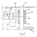
- Figure 5 shows an alternate embodiment of the structure of Figure 2, wherein the third element 38 is replaced by an alternate third element 138 which is located axially between the first and second elements 34, 36.
- the first arm 40 and the second arm 42 are deleted as the third element 138 expands or contracts to directly translate the unclamped respective one of the first element 34 and the second element 36.
- the head carrier 24 has been replaced with an alternately configured head carrier 124.
- the first element 34, the second element 36, and the third element 138 behave in similar synchronous fashion to that described in Figures 3A-3C and Figure 4.
- the second element 36 can remain clamped and the positioning of the head 20 up and down can be achieved solely through the expansion and contraction of the third element 138.
- the range R would thus be limited to the maximum expansion or contraction ot the third element 138 depending on the voltage applied thereto.
- the range R would be 0-10 ⁇ m. This is particularly useful in a closed loop track servo wherein the head must move quickly up and down continuously, so that the head can follow a prerecorded servo track on the tape.
- the disclosed system can be used to advantage in any size drive format.
- the center line of the tape 16 is indicated as CL1.
- Figure 5 shows in dashed lines the upper translated position of the head 20 indicated as 20'. In this position the center line of the head 20 is located at CL2.
- the range difference a between CL1 and CL2 is 3.5 mm in the preferred embodiment. Also shown in dashed lines is the lowest range position of the head 20 indicated as 20". The center line of the head 20 at this lowest position is indicated as CL3.
- the range difference b between CL1 and CL3 is also 3.5 mm.
- the unclamped element either element 34 or element 36 can move up approximately 10 ⁇ m in the expected embodiment.
Landscapes
- Adjustment Of The Magnetic Head Position Track Following On Tapes (AREA)
Description
Claims (9)
- A read/write apparatus (10) containing a device for positioning a magnetic head (20) relative to a selected one of a plurality of tracks of a magnetic tape (20), said tracks extending parallel to a tape transport direction in said device, comprising:characterized in thata magnetic tape recorder housing frame;a position actuator (38, 138);a magnetic head carrier (24, 124) mounted to said position actuator;a magnetic head (20) secured to said magnetic head carrier (24, 124) ;said magnetic tape recorder housing frame comprises a shaft (50) and means for mounting the shaft in a fixed manner perpendicular to said tape transport direction;said position actuator (38, 138) comprises an element having a portion thereof which can be altered in length between a first end and a second end thereof perpendicular to said tape transport direction by electrical stimulation thereof;said portion of said position actuator (38, 138) is connected at said first end to a first clamp actuator (34) and connected at said second end to a second clamp actuator (36);said magnetic head carrier (24, 124) is mounted to said first clamp actuator (34);said portion of said position actuator (38, 138) is electrically stimulatable to selectively extend or retract said magnetic head carrier (24, 124) in a direction perpendicular to said tape transport direction.
- A device as defined in claim 1, characterized in thatand further characterized bysaid first clamp actuator (34) is at least partially surrounding said shaft (50) and slidable along said shaft (50) and electrically stimulatable to grip said shaft (50);said second clamp actuator (36) is at least partially surrounding said shaft (50) and slidable along said shaft (50) and electrically stimulatable to grip said shaft (50) and spaced from said first clamp actuator (34);means for repeatedly alternatingly electrically stimulating said first and second clamp actuators (34, 36) for causing one of said clamp actuators to grip said shaft (50) while the other of the clamp actuator is free to slide along said shaft (50); andmeans for repeatedly electrically stimulating said portion of said position actuator (38, 138), coordinated with the stimulation of said first and second clamp actuators (34, 36), for altering said length of said portion for advancing, in a selected direction, said clamp which is free to slide along said shaft (50) to progressively move said magnetic head (20) to a selected position.
- A device as defined in claim 1 or 2, wherein said first clamp actuator (34) and said second clamp actuator (36) and said position actuator (38, 138) comprise piezoelectric elements.
- A device as defined in claim 1 or 2, wherein said first clamp actuator (34) and said second clamp actuator (36) and said position actuator (38, 138) comprise plunger-type solenoid elements.
- A device as defined in claims 1 to 4, wherein said first clamp actuator (34) and said second clamp actuator (36) are ring-shaped elements slidably mounted on said shaft (50).
- A device as defined in claims 1 to 5, wherein said position actuator (38) comprises a first arm (40) connecting said first end of said portion to said first clamp actuator (34); and
a second arm (42) connecting said second end of said portion to said second clamp actuator (36). - A device as defined in claims 1 to 6, wherein said first clamp actuator (34), said second clamp actuator (36) and said position actuator (38) comprise cylindrical shapes, and are stacked axially on said shaft (50).
- A method for positioning a magnetic head (20) relative to a select one of a plurality of tracks of magnetic tape (16) in a magnetic tape write/read device, said tracks extending parallel to a tape transport direction in said device, comprising the steps of:
providing a magnetic head (20) facing said magnetic tape (10) and mounted to a servo system (30)
characterized byproviding a shaft (50) arranged generally parallel to a width of the magnetic tape (16) to be read, said servo system being slidable on said shaft;providing the servo system with a clamping and extending mechanism, said extending mechanism being stimulatable to alter in length; andsequentially actuating said clamping and extending mechanism to move said servo system and said magnetic head progressively along said shaft in a selected direction. - The method according to claim 8, characterized in thatsaid clamping and extending mechanism comprises a first clamp actuator (34) mounted slidably on said shaft; a second clamp actuator (36) mounted slidably on said shaft and spaced from said first clamp actuator; a position actuator (38) having a portion thereof which can be expanded or contracted in length, said portion connected at a first end of said first clamp actuator (34) and connected to a second edge of said second clamp actuator (36); said first clamp actuator (34) and said second clamp actuator (36) being selectively electrically stimulatable to grip said shaft (50) to prevent axial movement of the respective clamp actuator with respect to said shaft (50); said portion of said position actuator (38) electrically stimulatable to selectively extend retract from said first clamp actuator (34) with respect to said second clamp actuator (36); wherein said sequentially actuating comprises the steps of:stimulating said second clamp actuator (36) to clamp said shaft (50);stimulating said position actuator (38) to extend said portion;stimulating said first clamp actuator (34) to grip the shaft (50) ;destimulating said second clamp actuator (36) to release said second clamp actuator (36) from said shaft (50);destimulating said position actuator (38) to retract said portion; andrepeating these latter five steps, as a cycle, a selective number of times.
Applications Claiming Priority (2)
| Application Number | Priority Date | Filing Date | Title |
|---|---|---|---|
| US81516791A | 1991-12-31 | 1991-12-31 | |
| US815167 | 1991-12-31 |
Publications (3)
| Publication Number | Publication Date |
|---|---|
| EP0550074A2 EP0550074A2 (en) | 1993-07-07 |
| EP0550074A3 EP0550074A3 (en) | 1993-09-22 |
| EP0550074B1 true EP0550074B1 (en) | 1998-06-10 |
Family
ID=25217065
Family Applications (1)
| Application Number | Title | Priority Date | Filing Date |
|---|---|---|---|
| EP19920122171 Expired - Lifetime EP0550074B1 (en) | 1991-12-31 | 1992-12-30 | Magnetic head servo system with steppermotor for head positioning |
Country Status (3)
| Country | Link |
|---|---|
| EP (1) | EP0550074B1 (en) |
| JP (1) | JP2569253B2 (en) |
| DE (1) | DE69225878T2 (en) |
Families Citing this family (2)
| Publication number | Priority date | Publication date | Assignee | Title |
|---|---|---|---|---|
| JP3087715B2 (en) | 1998-02-19 | 2000-09-11 | 日本電気株式会社 | Magnetic disk drive |
| CN102441796B (en) * | 2011-07-08 | 2013-08-07 | 吉林大学 | Ultraprecise piezoelectric stepping rotation driving platform capable of regulating speed mechanically |
Family Cites Families (6)
| Publication number | Priority date | Publication date | Assignee | Title |
|---|---|---|---|---|
| NL7907219A (en) * | 1979-09-28 | 1981-03-31 | Philips Nv | APPARATUS FOR RECORDING AND / OR PLAYING MAGNETIC SIGNALS INCLUDED ON A MAGNETIC BAND IN A NUMBER OF PARALLEL LONGITUDINAL TRACKS. |
| JPS58177567A (en) * | 1982-04-12 | 1983-10-18 | Canon Inc | Tracking or azimuth compensating device |
| DE3242334A1 (en) * | 1982-11-16 | 1984-06-28 | CEC Datentechnik GmbH, 6360 Friedberg | Device and control means of the reproducing head for improving the readability of linear multi-track data recordings on measuring magnetic tape apparatuses |
| JPS60124018A (en) * | 1983-12-07 | 1985-07-02 | Tokyo Electric Co Ltd | Tracking mechanism of magnetic recorder |
| JPS60217415A (en) * | 1984-04-13 | 1985-10-31 | Toshiba Corp | Actuator |
| JPS6223381A (en) * | 1985-07-23 | 1987-01-31 | Ube Ind Ltd | Piezoelectric type actuator |
-
1992
- 1992-12-25 JP JP4346201A patent/JP2569253B2/en not_active Expired - Lifetime
- 1992-12-30 EP EP19920122171 patent/EP0550074B1/en not_active Expired - Lifetime
- 1992-12-30 DE DE1992625878 patent/DE69225878T2/en not_active Expired - Fee Related
Also Published As
| Publication number | Publication date |
|---|---|
| DE69225878D1 (en) | 1998-07-16 |
| EP0550074A3 (en) | 1993-09-22 |
| EP0550074A2 (en) | 1993-07-07 |
| JPH05266445A (en) | 1993-10-15 |
| JP2569253B2 (en) | 1997-01-08 |
| DE69225878T2 (en) | 1998-10-15 |
Similar Documents
| Publication | Publication Date | Title |
|---|---|---|
| US6807030B1 (en) | Enclosed piezoelectric microactuators coupled between head and suspension | |
| EP0160707B1 (en) | Piezoelectric stepping rotator | |
| Eleftheriou | Nanopositioning for storage applications | |
| US4578607A (en) | Piezoelectric precise rotation mechanism for slightly rotating an object | |
| JPH1090584A (en) | Lens device | |
| EP0550074A2 (en) | Magnetic head stepping servo system for a tape drive unit | |
| US7567019B2 (en) | Actuator system | |
| DE60115272T2 (en) | PROBE FOR EXACT MOVEMENT AND LOW POWER CONSUMPTION | |
| US7309946B2 (en) | Motion actuator | |
| US7308694B2 (en) | High-precision positioning apparatus | |
| US7129622B2 (en) | Driving apparatus, use thereof and an optical system comprising such apparatus | |
| JPS63274894A (en) | Feeder | |
| Ma et al. | High-bandwidth macro/microactuation for hard-disk drive | |
| JPH09114526A (en) | Object positioning device | |
| JPH01187402A (en) | Scan tunnel microscope | |
| US6975481B1 (en) | Driver systems and methods for an actuator of a hard disk drive | |
| JPS62287480A (en) | Head actuator for magnetic disk unit | |
| Afzulpurkar et al. | Precision positioning using MEMS based microactuator | |
| JP2633910B2 (en) | Substrate surface deformation device | |
| US5640289A (en) | Apparatus and method for non-friction and non-sliding contact of an access arm during merging of a computer mass storage device | |
| SU1617556A1 (en) | Linear stepping motor | |
| JP2730048B2 (en) | Driving method of linear pulse motor | |
| JPS60249553A (en) | Positioning device for fine machining | |
| JPS63106971A (en) | Recording and reproducing device | |
| KR100331450B1 (en) | Small scale and high density data storage apparatus using probe |
Legal Events
| Date | Code | Title | Description |
|---|---|---|---|
| PUAI | Public reference made under article 153(3) epc to a published international application that has entered the european phase |
Free format text: ORIGINAL CODE: 0009012 |
|
| AK | Designated contracting states |
Kind code of ref document: A2 Designated state(s): DE FR GB |
|
| PUAL | Search report despatched |
Free format text: ORIGINAL CODE: 0009013 |
|
| AK | Designated contracting states |
Kind code of ref document: A3 Designated state(s): DE FR GB |
|
| 17P | Request for examination filed |
Effective date: 19940224 |
|
| 17Q | First examination report despatched |
Effective date: 19951214 |
|
| GRAG | Despatch of communication of intention to grant |
Free format text: ORIGINAL CODE: EPIDOS AGRA |
|
| GRAG | Despatch of communication of intention to grant |
Free format text: ORIGINAL CODE: EPIDOS AGRA |
|
| GRAH | Despatch of communication of intention to grant a patent |
Free format text: ORIGINAL CODE: EPIDOS IGRA |
|
| GRAH | Despatch of communication of intention to grant a patent |
Free format text: ORIGINAL CODE: EPIDOS IGRA |
|
| RAP1 | Party data changed (applicant data changed or rights of an application transferred) |
Owner name: TANDBERG DATA ASA |
|
| GRAA | (expected) grant |
Free format text: ORIGINAL CODE: 0009210 |
|
| AK | Designated contracting states |
Kind code of ref document: B1 Designated state(s): DE FR GB |
|
| REF | Corresponds to: |
Ref document number: 69225878 Country of ref document: DE Date of ref document: 19980716 |
|
| ET | Fr: translation filed | ||
| PLBE | No opposition filed within time limit |
Free format text: ORIGINAL CODE: 0009261 |
|
| STAA | Information on the status of an ep patent application or granted ep patent |
Free format text: STATUS: NO OPPOSITION FILED WITHIN TIME LIMIT |
|
| 26N | No opposition filed | ||
| PGFP | Annual fee paid to national office [announced via postgrant information from national office to epo] |
Ref country code: FR Payment date: 20001221 Year of fee payment: 9 |
|
| PGFP | Annual fee paid to national office [announced via postgrant information from national office to epo] |
Ref country code: GB Payment date: 20001227 Year of fee payment: 9 |
|
| PGFP | Annual fee paid to national office [announced via postgrant information from national office to epo] |
Ref country code: DE Payment date: 20010124 Year of fee payment: 9 |
|
| PG25 | Lapsed in a contracting state [announced via postgrant information from national office to epo] |
Ref country code: GB Free format text: LAPSE BECAUSE OF NON-PAYMENT OF DUE FEES Effective date: 20011230 |
|
| REG | Reference to a national code |
Ref country code: GB Ref legal event code: IF02 |
|
| PG25 | Lapsed in a contracting state [announced via postgrant information from national office to epo] |
Ref country code: DE Free format text: LAPSE BECAUSE OF NON-PAYMENT OF DUE FEES Effective date: 20020702 |
|
| GBPC | Gb: european patent ceased through non-payment of renewal fee |
Effective date: 20011230 |
|
| PG25 | Lapsed in a contracting state [announced via postgrant information from national office to epo] |
Ref country code: FR Free format text: LAPSE BECAUSE OF NON-PAYMENT OF DUE FEES Effective date: 20020830 |
|
| REG | Reference to a national code |
Ref country code: FR Ref legal event code: ST |